2005 International Linear Collider Workshop - Stanford,
U.S.A.
The 2mrad horizontal crossing angle IR layout for a TeV ILC
Abstract
The current status of the 2mrad crossing angle layout for the ILC is reviewed. The scheme developed in the UK and France is described and the performance discussed for a TeV machine. Secondly, the scheme developed at SLAC and BNL is then studied and modified for a TeV machine. We find that both schemes can handle the higher energy beam with modifications, and share many common features.
I INTRODUCTION
In this article, we describe the recent development of the 2mrad horizontal crossing angle scheme for the ILC. To date, two parallel designs have emerged: the first coming from the UK and France and the second from SLAC and BNL. We shall describe both schemes here, although they share many common features and are now being developed in parallel under the unified SLAC-BNL-UK-France task force collaboration. The work presented focuses on the performance at 1 TeV. The benefits of the scheme are well documented Appleby:2004df : for small crossing angles, the loss of luminosity is small (crab correction may not be necessary and it may be possible to partially correct this loss by exploiting the finite at the IP for local chromaticity correction lattices), no electrostatic separators or kicker magnets are needed and the conditions are improved for physics (e.g. better forward coverage). A known weakness of this scheme is however its more difficult conditions for extracting cleanly the spent disrupted and energy-degraded beam, in comparison with larger crossing-angle schemes where separate magnetic channels can be used for in-and outgoing beams.
The work presented here covers the designs developed at SLAC, BNL, the UK and France. In section II we shall describe the scheme developed in Europe and discuss its performance at 1 TeV. In section III, we shall discuss the performance of the SLAC/BNL scheme, when extended to 1 TeV from the initial design at 500 GeV, and we shall draw our conclusions in section IV.
II The UK/FRANCE EXTRACTION LINE DESIGN AND PERFORMANCE AT 1 TEV
In this section we shall describe the 2mrad interaction region layout and extraction line for the 2mrad horizontal crossing angle scheme.
The final doublet magnets have been optimised for the extraction of a 500 GeV beam. A similar optimisation exists for the baseline beam energy of 250 GeV. It has been shown that the doublet parameters calculated for a high energy beam also provide acceptable extraction at lower energy. The superconducting magnet closest to the IP, denoted QD, is of critical importance to the IR layout properties and is chosen to be a LHC low--insertion quadrupole. This provides the required aperture and field strength to accommodate both the incoming and outgoing (disrupted) beams. Note that the outgoing beam possesses a long low energy tail and, by virtue of the crossing angle, is off-axis in QD. The other final doublet magnet, QF, is constructed from a normal conducting magnet and is separated from QD by 3m. For the TeV machine, QD and QF are 2.3m and 1.9m long, respectively. After passing through QD, the outgoing disrupted beam enters the extraction line, which provides beam transport to the dump and downstream diagnostics (the geometry is fixed by the linear matrix element from the IP to the exit of QD).
The LHC low--region quadrupoles are constructed from NbTi and can achieve a gradient of 215 Tm-1 with an available aperture for the beam of 62mm. Note that higher gradients are currently under development, which will aid the present application. LHC studies of the tolerable power depostion indicate local and integral values of 0.4 mWg-1 and 5 Wm-1 respectively; this approximately translates into a maximum power deposition from charged particles into QD of around 10W.
Note that in all these studies, unless otherwise noted, we assume the parameters of the TeV ILC parameters working group and, where possible, assume the worst possible parameter set for extraction. In this work, we follow applebyandbambade and assume a photon cone half-opening angle of 0.5mrad in all cases. This ensures that the cone contains all the photon power, apart from 100W. This remaining power needs to be lost in suitable collimators. Ensuring extraction of the photons past QF immediately requires a crossing angle of greater than 1.6mrad.
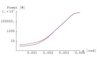
Figure 1 shows the power deposition into QD from charged particles produced during the beam-beam interaction, as a function of crossing angle. These power deposition calculations are described in detail in applebyandbambade2 . The charged particle loss comes from two sources: the low energy tail of the disrupted beam and from radiative Bhabha events produced in the interaction of colliding particles (also refered to as the “Compton tail”). The latter contribution is suppressed in regions of phase space of low transverse momentum exchange, where the virtual photons participating in the scattering process can have a transverse position indeterminacy exceeding the transverse beam size. The suppression from this so-called beam-size effect is illustrated in the curves of fig. 1. Conservatively, the results without it are however used for the worst-case scenarios considered here. If we assume a maximun power loss of 10W, we find that for the case of a TeV machine with a bunch population of 21010, we can tolerate a crossing angle no larger than 1.6mrad. This result is dominated by the Compton tail. The other case we have considered in figure 1 shows a larger permitted crossing angle, and hence easier extraction. This case, with a vertical offset of 150nm at the IP, is studied because it maximises the low energy tail of the disrupted beam. For further details of these calculations see applebyandbambade2 . All of these curves were produced using the US cold machine parameters, for which the key parameters (for this study) are similar to the WG 1 new ILC nominal parameters wg1 .
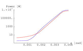
The purpose of the extraction line is to transport the disrupted beam to the dump with controlled and acceptable losses, handle the undisrupted beam in the case of single beam operation (e.g. during commissioning) and to provide diagnostics on the disrupted beam. The possible diagnostics include Compton polarimetry and energy spectrometry. The linear dispersion for the extraction line is shown in the left-hand plot of figure 2. The linear dispersion allows identification of the major optical structures, denoted by regions of non-zero dispersion. The first region is the dispersion generated by the beam being off-axis in QD (the first magnet in the line). This dispersion is cancelled by a mirroring dipole. The second dispersive region is a “bend-back” linear-achromatic structure, which bends the beam parallel to the beam at the IP. This is necessary to perform Compton polarimeter and “undo” the spin precession occuring in upstream dipoles. The third region is the diagnostic chicane; the current requirements for this chicane is a secondary beam focus and some dispersion, such that the dispersive beam size dominates the betatron beam size. Requirements of beamsize/laser wavelength correlation and of minimum background requirements are under study.

The first magnet in the extraction line is of critical importance, due to the need to place the first disrupted beam magnet as close as possible to the IP, balanced against the constraints of transverse space. For this reason, a half-quadrupole current sheet magnet is used teslatdr . These magnets, developed for the TESLA extraction line teslatdr provide the required aperture and maximum pole tip field whilst allowing the magnet to be placed 8m after the exit of QD (with 50mm transverse separation). Note that other magnet designs are under study.
The right-hand plot of figure 2 shows the optimisation of the apertures for a fixed power loss. We have used the TeV machine nominal parameters and demanded a power loss of 0.5ppm at each element. We also considered a vertical offset of 120nm. The apertures were calculated using explicit all-orders ray-tracing of the disrupted beam. The calculated apertures are acceptable, although the very downstream apertures for the TeV machine need some optimisation.
The study of this scheme is on-going. It is necessary to include the effects on the outgoing beam of all the fields from nearby magnets used to focus the incoming beam, in particular QF. This can be done by way of suitable multipole expansions, once the detailed field map is computed. It has been shown to be particularly critical to predict reliably the transport of the low-energy tail of the extracted beam yuritalk . Furthermore the magnet technology is of prime importance, and substitutes for the half-quadrupole described here are under consideration, along with the use of sextupoles in the extraction line to aid the control of the low energy beam tail. The layout of the charged particle and photon beam dumps is also a topic for further work, along with detailed calculations of backgrounds in the detector and diagnostic sections.
III The SLAC-DEVELOPED DESIGN EXTENDED TO 1 TEV
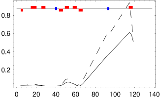
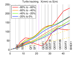
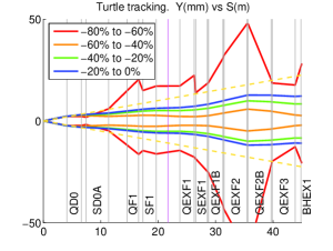
In this section, we describe the performance of the SLAC/BNL-designed 2 mrad scheme, when extended to the upgrade centre-of-mass energy of 1 TeV. This scheme, described in yuritalk , was studied at 1 TeV using the nominal parameters and a vertical offset of 100nm. This gives a low energy Beamstrahlung tail reaching down to 18% of maximum energy, when computed with high statistics. Extending the design to 1 TeV required a number of modifications to the initial design for 500 GeV: proper scaling of the lengths of sextupoles to keep the pole tips within maximum achievable fields, increasing L* from 3.51m to 4.1m and reducing the length of QD0 to reduce over focusing of low energy tail particles. In order to reduce the losses of the low energy tail particles on the magnets, a collimator was introduced in the vertical plane within the final doublet. The horizontal and vertical beam envelopes for this scheme are shown in figure 3, for particles in different energy ranges.
Note that this is a first look at the TeV upgrade of this scheme and further optimisation and power losses on the magnets needs to be evaluated.
IV CONCLUSION
We have described the 2mrad horizontal crossing angle schemes under development for the ILC. The first part described the scheme developed in the UK and France, and focused on its propeties at 1 TeV. The second describes the study of the SLAC and BNL scheme from these proceedings, when extending the design to 1 TeV. Both schemes at 1 TeV can work with nominal parameters but the high luminosity case seems difficult. Further development work is ongoing. Finally we note that both schemes share many common features.
Acknowledgements.
We would like to thank Cherrill Spencer and Brett Parker for useful conversations and advice.References
- (1) R. Appleby et al, “Alternative IR geometries for TESLA with a small crossing angle,” The proceedings of LCWS04, Paris, France. hep-ex/0412026.
- (2) R. Appleby and P. Bambade, “Beamstrahlung photon cones in the interaction region of the ILC”, CARE/ELAN document 2004-21.
- (3) R. Appleby and P. Bambade, “Beam-beam induced charged particle losses in the final quadrupole of the ILC”, Under preparation.
- (4) http://www-project.slac.stanford.edu/ilc/acceldev/beamparameters.html.
- (5) R. Brinkmann et al, “The TESLA technical design report”.
- (6) Y. Nosochkov et al, See the paper in these proceedings.