Abstract
The HERA-B Outer Tracker is a large system of planar drift chambers with about 113 000 read-out channels. Its inner part has been designed to be exposed to a particle flux of up to cm-2s-1, thus coping with conditions similar to those expected for future hadron collider experiments. 13 superlayers, each consisting of two individual chambers, have been assembled and installed in the experiment. The stereo layers inside each chamber are composed of honeycomb drift tube modules with 5 and 10 mm diameter cells. Chamber aging is prevented by coating the cathode foils with thin layers of copper and gold, together with a proper drift gas choice. Longitudinal wire segmentation is used to limit the occupancy in the most irradiated detector regions to about 20 %. The production of 978 modules was distributed among six different laboratories and took 15 months. For all materials in the fiducial region of the detector good compromises of stability versus thickness were found. A closed-loop gas system supplies the Ar/CF4/CO2 gas mixture to all chambers. The successful operation of the HERA-B Outer Tracker shows that a large tracker can be efficiently built and safely operated under huge radiation load at a hadron collider.
The Outer Tracker Detector of the HERA-B Experiment
Part I: Detector
HERA-B Outer Tracker Group
H.Albrechth, Th.S.Bauera,q, M.Beckp, K.Berkhanr, G.Bohmr, M.Bruinsmaa,q, T.Burano, M.Capeansh, B.X.Chend, H.Deckerse, A.Donatr, X.Dongc, R.Eckmannb, D.Emelianovh, G.Evgrafovh,s, I.Golutving, U.Harderr, M.Hohlmannh, K.Höpfnerh, W.Hulsbergena, Y.Jiac, C.Jiangc, H.Kapitzaf, S.Karabekyanp,u, Z.Kec, Y.Kiryushing, H.Kolanoskie, D.Krückere, A.Lanyovg, Y.Q.Liud, T.Lohsee, H.Lüdecker, R.Mankele, G.Medine, E.Michelh, A.Moshking, J.Nid, S.Nowakr, M.Ouchrifa,q, C.Padillah, R.Pernackp, A.Petrukhinh,n, D.Poseg,j, B.Schmidth, W.Schmidt-Parzefalli, A.Schreinerr, H.Schröderh,p, U.Schwanker, A.S.Schwarzh, I.Siccamah, K.Smirnovr, S.Soluning, S.Somovh, V.Souvorovr, A.Spiridonovr,n, C.Stegmannr,e, O.Steinkampa, N.Teschh, I.Tsakovh,t, U.Uwere,j, S.Vassilievg, D.Vishnevskyg, I.Vukotice, M.Walterr, J.J.Wangd, Y.M.Wangd, R.Wurthh, J.Yangd, Z.Zhengc, Z.Zhuc, R.Zimmermannp
aNIKHEF, Kruislaan 409, PO Box 41882, 1009 DB Amsterdam,
Netherlands1
bUniversity of Texas at Austin, Department of Physics,
RLM 5.208, Austin TX 78712-1081, USA2
cInstitute of High Energy Physics, Beijing 100039, China
dInstitute of Engineering Physics, Tsinghua University,
Beijing 100084 , P.R. China
eInstitut für Physik, Humboldt-Universität zu Berlin,
D-12489 Berlin, Germany3
fInstitut für Physik, Universität Dortmund, D-44221
Dortmund, Germany3
gJoint Institute for Nuclear Research, Dubna, RU-141980,
Russia
hDESY, Notkestraße 85, D-22607 Hamburg, Germany
iInstitut für Experimentalphysik, Universität Hamburg,
D-22761 Hamburg, Germany3
jPhysikalisches Institut, Universität Heidelberg,
D-69120 Heidelberg, Germany3
nInstitute of Theoretical and Experimental Physics,
117259 Moscow, Russia
oInstitute of Physics, University of Oslo,
Norway4
pFachbereich Physik, Universität Rostock,
D-18051 Rostock, Germany3
qUniversiteit Utrecht/NIKHEF, 3584 CB Utrecht,
The Netherlands1
rDESY, Platanenallee 6, D-15738 Zeuthen,
Germany
svisitor from Moscow Physical Engineering Institute,
115409 Moscow, Russia
tvisitor from Institute for Nuclear Research, INRNE-BAS,
Sofia, Bulgaria
uvisitor from Yerevan Physics Institute, Yerevan, Armenia
1supported by the Foundation for Fundamental Research on
Matter (FOM), 3502 GA Utrecht, The Netherlands
2supported by the U.S. Department of Energy (DOE)
3Supported by Bundesministerium für Bildung und Forschung,
FRG, under contract numbers
05-7BU35I, 05-7D055P, 05 HB1KHA, 05 HB1HRA, 05 HB9HRA, 05
7HD15I,
05 7HH25I
4Supported by the Norwegian Research Council
1 Introduction
HERA-B is a fixed target experiment using the 920 GeV proton beam of the HERA electron-proton collider [1, 2]. Proton-nucleus interactions are produced using an internal wire target in the halo of the proton beam which allows for concurrent operation with the collider experiments. The design of the experiment was driven primarily by the physics goal of studying CP violation in the decay , requiring high event rates and particle flux, efficient particle identification and triggering.
The HERA-B spectrometer, schematically shown in Fig. 1, covers in the bending plane an angular range from 10 mrad to 220 mrad, corresponding to about 90 solid-angle coverage in the center-of-mass system.
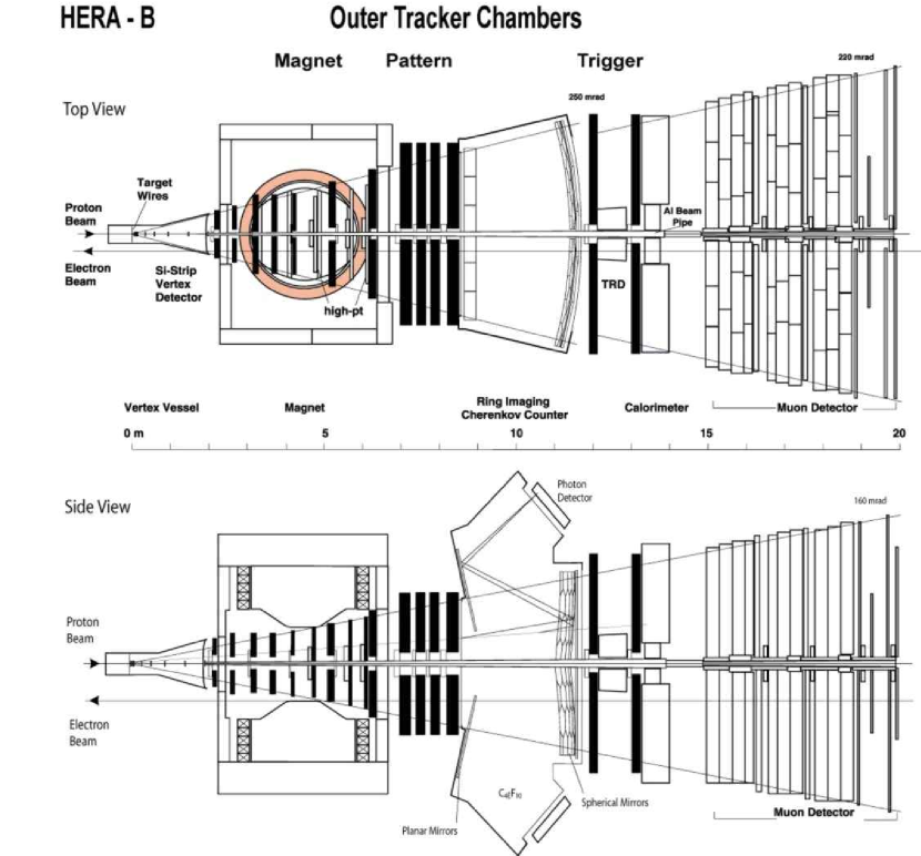
The main components of the spectrometer are the following:
-
•
The halo target station [3] consists of two sets of 4 wires, separated along the beam by 5 cm. This allows to localize the vertices of proton-nucleus interactions at very high rates of up to 40 MHz with 4 to 5 interactions per proton bunch. Most data were taken using carbon and tungsten targets, but for the study of dependencies other materials such as titanium and aluminum have been used as well.
-
•
The vertex detector system (VDS) [4], based on silicon strip detector technology, starts at 1 cm radius from the beam. The detector consists of 8 superlayers extending over a length of 2 m along the beam. This allows a stand-alone pattern recognition of tracks and the reconstruction of both interaction and decay vertices.
-
•
The normal-conducting dipole magnet for momentum analysis has a field integral of 2.2 Tm. The magnet aperture is 160 mrad vertically and 220 mrad horizontally.
-
•
The main tracking system consists of detector components with different granularities and technologies varying with the distance from the proton beam pipe. To limit the occupancy of detector cells and to minimize the number of channels, the tracking system is divided into an inner and an outer part. For the Inner Tracker (ITR) [5] microstrip gas chambers with a gas electron multiplier (GEM) foil are used covering the regions between about 6 cm and 20 to 25 cm from the beam axis. The strip pitch is 300 m. The Outer Tracker (OTR), based on drift chamber technology, will be discussed in this paper.
- •
The detector is optimized to run at interaction rates up to 40 MHz and to deal with up to 200 charged particle tracks every 96 ns. This results in a high radiation load, comparable to conditions at LHC experiments. To guarantee that the detector components sustain a running period of about 5 years, extensive aging studies for most of the components were performed [9].
A selection of the decay mode requires a trigger system which reduces the background by a factor of about . The HERA-B detector with its trigger and data acquisition system is flexible enough to access a wide range of additional physics topics like production cross section, heavy-quark physics, and production mechanisms as well as minimum bias physics. Detailed descriptions of the HERA-B detector and its capabilities are given elsewhere [1, 2, 10].
2 General Design Aspects
2.1 Detector Requirements
The design of the Outer Tracker and the choice of technology is driven by requirements of the physics program, space constraints in the experimental area, cost optimization, and feasibility of large-scale production. The OTR is designed to serve the following purposes:
-
•
Efficient reconstruction of charged particle tracks from a distance of 20 cm from the HERA proton beam up to the outer acceptance limit of the experiment.
-
•
Precise momentum measurement together with the vertex detector system and the dipole magnet.
-
•
Providing fast trigger signals for the first level trigger (FLT) in the environment of high track density.
-
•
Tracking inside the magnet to provide vertex and momentum information of mesons decaying in the magnet.
These demands require an OTR detector with good performance in terms of rate capability, spatial resolution, and hit and tracking efficiencies. It also requires a fast drift gas, for which an Ar/CF4/CO2 mixture was chosen. In addition, the amount of material in the tracking detector has to be small to minimize effects of bremsstrahlung, photon conversion, multiple scattering, and hadronic interactions.
2.2 Particle Rate and Occupancy
One of the most important requirements is the high rate capability of the OTR. At 40 MHz interaction rate the detector has to deal with about 100 charged primary and secondary particles per proton bunch. The radial dependence of the particle flux is particles per second. Here denotes the radial distance from the proton beam (Fig. 2).
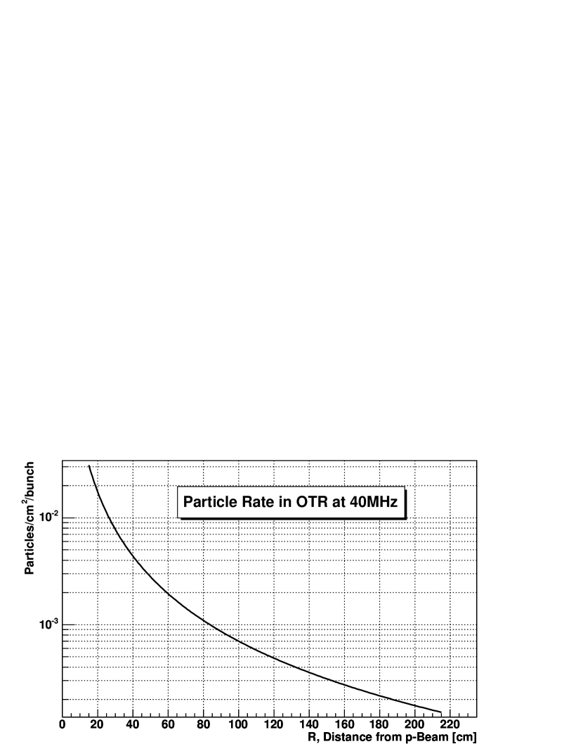
In the inner part of the OTR, at = 20 cm, the hit occupancy in an event is almost 2 per of the detector cross section. The occupancy drops by two orders of magnitude in the outer region at = 200 cm. Efficient pattern recognition of all charged tracks and the FLT tracking of charged leptons demand detector occupancies of less than 20 . For higher occupancies the rate of misreconstructed tracks increases and both, pattern recognition and tracking on the FLT level become inefficient. High occupancies require a high detector granularity and this influences strongly the choice of detector technology and read-out electronics. Compared with previous and existing experiments occupancies of 20 are very high.
2.3 Global Outer Tracker Design
The Outer Tracker system consists of three different parts:
-
•
Magnet Chambers (MC) for tracking inside the magnetic field,
-
•
Pattern Recognition Chambers (PC) in the field-free region between the magnet and the RICH for track reconstruction and for triggering,
-
•
Trigger Chambers (TC) for the tracking of leptons in front of the ECAL and for triggering.
| Superlayer | Thickness | Width | Height | Layers | |
| [cm] | [cm] | [cm] | [cm] | ||
| MC1 | 219 | 10 | 116 | 75 | 0 |
| MC2 | 266 | 10 | 140 | 90 | 0 |
| MC3 | 315 | 15 | 167 | 122 | 0 |
| MC4 | 365 | 15 | 196 | 122 | 0 |
| MC5 | 422 | 5 | 208 | 129 | 0 |
| MC6 | 513 | 18 | 277 | 150 | 0 |
| MC8 | 621 | 18 | 332 | 206 | 0 |
| PC1 | 702 | 28 | 416 | 276 | 0 0 |
| PC2 | 742 | 23 | 416 | 276 | 0 0 0 |
| PC3 | 778 | 23 | 416 | 276 | 0 0 0 |
| PC4 | 823 | 28 | 416 | 276 | 0 0 |
| TC1 | 1192 | 20 | 524 | 446 | |
| TC2 | 1306 | 20 | 580 | 446 |
The track reconstruction requires a sufficient number of hits measured in each of the three tracker parts. As shown in Fig. 1, the Outer Tracker comprises 13 so called superlayers (7 MC, 4 PC and 2 TC) each of which is vertically divided into two chambers. Each chamber is an independent device with its own gas and power connections and its own read-out electronics system.
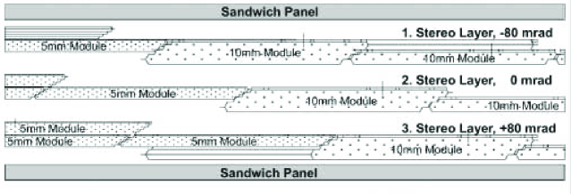
In order to allow a 3-dimensional track measurement, all superlayers but MC5 are combinations of three types of stereo layers with wires at angles of 0, 80 and -80 mrad w.r.t. the vertical direction. The small stereo angle helps to suppress hit ambiguities during pattern recognition, at the expense of an increased spatial resolution in the vertical direction. Table 1 summarizes for all superlayers the position of the front plane, the dimensions and the layer structure.
A viable technology for building a tracking detector with the specified dimensions are drift tubes, where each anode wire is located in the center of a cathode tube made of a thin conductive foil. Compared to drift chambers with cathode wires, drift tubes offer several advantages: Due to the much lower electric field on the cathode it is easier to avoid aging effects, single broken wires are less dangerous for the functionality of the whole detector, and the tubes are mechanically self-supporting. The last fact makes it easy to group drift tubes in modules. The module size can be chosen to best fit the requirements of detector mass production and assembly.
Tracking in a high occupancy environment benefits from drift cells being as small as possible, but the operational safety of the detector sets a lower limit on the cell size. For the Outer Tracker a minimal drift tube diameter of 5 mm is chosen. Due to the dependence of the particle rate, tubes with double diameter (10 mm) can be used in the outer parts of the detector. This helps to minimize the channel count.
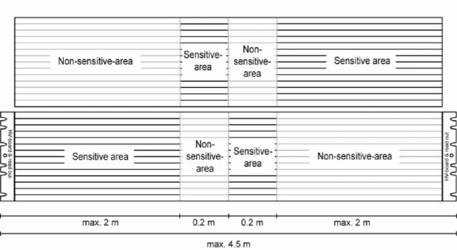
According to Fig. 2, there are up to 0.02 particles//bunch in the innermost area of the OTR. Because the cell occupancy is required to be smaller than 20 , the maximum cell length would be limited to 20 cm for 5 mm cells. Since the vertical dimension of the OTR ranges from 75 to 450 cm, the only solution is a longitudinal cell segmentation. The technical realization is described in section 3.1. In Fig. 3 the composition of a detector plane from individual detector modules and the segmentation into different sectors is shown schematically. Except for the outermost sectors 11 and 12, the anode wires are separated in the middle to obtain two independent parts of a cell, read out from top and bottom. In addition, 5 mm cells are segmented into inner sectors (3 - 6) with 20 cm long anode wires and outer sectors (1 and 2) with wire lengths of 25 - 205 cm, depending on the superlayer.
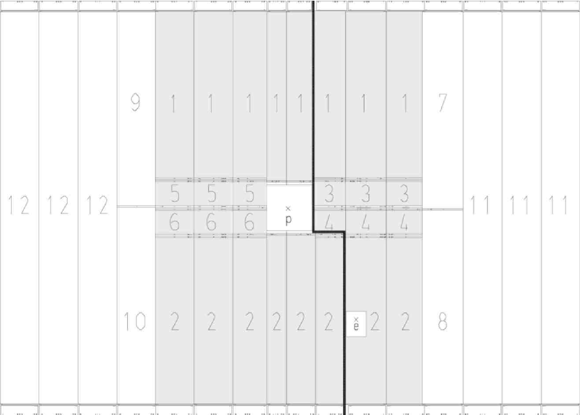
At the HERA-B detector, the HERA proton and electron beam lines are separated. The proton beam axis defines the central HERA-B detector axis. The electron beam pipe also passes through the detector. To minimize the dead area around the beam pipes and to allow an easy access, the superlayers are divided into two asymmetric chambers, where the separation follows the positions of the two beam pipes (see Fig. 3).
3 Detector Modules
3.1 Design Aspects
As was described in the previous section, the Outer Tracker is assembled from modules of drift tubes with 5 or 10 mm diameter and walls made of a light-weight conductive plastic foil. Instead of building modules from individual tubes, a honeycomb structure of hexagonal drift cells is constructed layer by layer from appropriately folded foils. The main advantage of this technology is the possibility to assemble the anode wires into open cells. This makes it easy to implement the longitudinal anode wire segmentation shown in Fig. 3.
Prototypes of drift chambers consisting of honeycomb cells with 15 mm cell diameter have been developed for the muon detector of the ATLAS experiment [13, 14]. Tests using conductive soot-loaded polycarbonate foil [14, 15, 16] and an automated folding device [13] showed that cells with only 5 mm diameter could be produced as well.
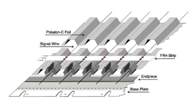
The assembly steps are indicated in Fig. 4. One can see the first wired cell layer before gluing the upper foil on the lower one to form a so-called monolayer. The simplest fully efficient detector plane, a so-called single layer, consists of two staggered monolayers, as shown in Fig. 5.
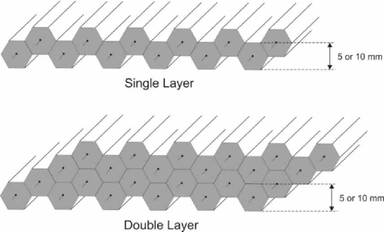
Single layer modules are used for detector planes which are not implemented in the trigger. They have no segmentation in case of 10 mm cells (sectors 11 and 12 in Fig. 3) and for modules with 5 mm cells installed above and below the proton beam pipe. The 10 mm modules of sectors 7 to 10 are divided into an upper and a lower part. The double layer structure shown in Fig. 5 is used for two classes of modules. First, it is needed to build 5 mm modules with 4 sensitive sectors (labelled 1-3-4-2 and 1-5-6-2 in Fig. 3). The details of the single layer structure for such a module are shown in Fig. 6, where also the longitudinal wire segmentation is described. In the second class of double layer modules both single layers have the same structure. This creates sensitive sectors with double coverage, where the logical OR of lined-up wires can be used to increase the hit efficiency. All OTR layers used in the FLT are of this type.
3.2 Module Types
The large-scale manufacturing of modules for superlayers of different structure and dimensions requires a detailed planning and preparation.
To minimize the number of different module types identical heights are chosen for the four PC and for the two TC superlayers (see Tab. 1). So-called standard modules with 5 mm drift cells are defined to have 32 cells per monolayer, which is a multiple of the 16 channels per signal read-out board [11]. For modules with 10 mm cells there are 16 cells per monolayer. This results in a module width of about 30 cm and is also a reasonable size for the complicated and heavy production templates (see Section 3.4). Another advantage is that even the 4.5 m long TC modules weigh only 1.5 kg and are light enough for an easy handling during manufacturing and for the installation into the superlayers.
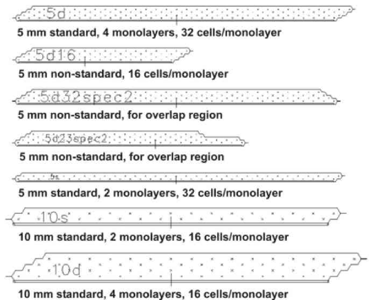
The complete Outer Tracker contains 978 honeycomb drift tube modules. Two thirds of these have drift cells with 5 mm diameter. In total, 148 types of modules with different widths, lengths, and internal structures had to be produced. There are 25 types of standard modules, just differing in length and/or drift cell size, which account for half the modules in the detector. Non-standard modules are needed mainly in the overlap of the two chambers of a superlayer, and around the proton and electron beam pipes. A few examples of module cross sections are shown in Fig. 7. With the trapezoidal module cross section, the cells of neighbouring modules are overlapping. As shown in Fig. 8 for 5 mm and 10 mm modules this overlap avoids an efficiency loss.
3.3 Module Components
As shown in Fig. 4, a module essentially consists of cathode foils, wire support strips, anode wires in the sensitive part and of end-pieces and base plates on both module ends for the fixation. The components and materials used in the module production will be described in more detail in the following. In Table 2 the product names, the producer and the approximate amount of all materials are summarized.
| Component | Material | Producer | Amount |
|---|---|---|---|
| Cathode | Pokalon-C foil, 75 m thick | [16] | 12000 |
| coated with Cu (50 nm) and Au (40 nm) | [20] | 1 m long foils | |
| Base Plates | FR4 (glass fiber laminate, matrix epoxy resin) | [21] | 2000 |
| End-pieces | Noryl (polyphenylen ether) | [22] | 20000 |
| Wire Support Strips | FR4 | [21] | 24000 |
| Glue | Stycast 1266A and Catalyst 9 | [23] | 40 kg |
| Conductive Glue | E-solder 3025 A+B | [24] | 1.5 kg |
| Signal Wire | 25 m gold-plated tungsten wire | [25] | 220000 m |
| Thick Wire | 75 m Cu + Be wire | [26] | 150000 m |
| Solder Tin | FLUITIN Sn60Pb | [27] | 10 kg |
| Carbon Fiber Rods | carbon fiber composite, 2 mm diam., 3 to 4.5 m long | [28] | 5000 |
| Aluminium Cover Foil | 10 m thick Al-foil | [29] | 6000 m |
Cathode Foil:
The cathode foils form the honeycomb structure of the drift cells and ensure the mechanical stability of the modules (see cross sections in Fig. 5). To minimize secondary interactions in the detector, the cell walls must be as thin as possible. A conductive foil type developed by Bayer [15], commercially available from the company LONZA [16], has the required properties which are summarized in Table 3. However, prototype modules built from this foil showed severe aging when operated at HERA [17]. This was caused by insufficient surface conductivity of the foil [18]. After detailed investigations, the problem could be solved by metal-coating of the foil. Using a plasma coating process, the foils were covered with a 50 nm thick copper and a 40 nm thick gold layer [20]. Copper alone is corroded by the fluoric radicals created by gas amplification in the Ar/CF4/CO2 drift gas mixture, and a direct gold coating has not sufficient adhesion on the Pokalon-C surface.
| Product name | Pokalon-C |
|---|---|
| Material | polycarbonate cast film with 6 soot |
| (82 C, 13 O, 4 H, 1 Cl) | |
| Residual solvent | 1.5 |
| Thickness | 75 m |
| Density | 1.35 |
| Tensile strength | 3800 |
| Thermal expansion | 0.07 mm/m/K |
| Water vapour permeability | 14 |
| Additional coating | copper (50 nm) / gold (40 nm) |
| Surface resistance | 1 / |
The first step in foil mass production was the folding of about 12000 foils of 1 m length and 40 cm width. The device and the folding procedure are described in detail in [13]. The folded foils are then tempered between two aluminum templates for about 20 minutes at a temperature of 120∘ C. In this way an accurate hexagonal shape with straight cell sides is obtained. The last step is the copper and gold coating of the foil surfaces.
Base Plates:
The base plates are glued to both module ends (see Fig. 4). They have accurate holes for the positioning and slits for the fixation of the module in the superlayer frame. The material is an epoxy/glass fibre multilayer (FR4) with very good mechanical properties and excellent chemical resistance. The plates are 70 mm wide to allow the mounting of high voltage boards, which provide the anode wires with high voltage and transfer the anode signals via twisted pair cables to the amplifier-shaper-discriminator (ASD-8) boards located outside of the gas box [11]. In order to reduce the amount of material, no base plates are used at the inner end of modules above and below the proton beam pipe.
End-Pieces:
The end-pieces (see Fig. 4) are plastic parts produced by a mould injection technique. In the first cell layer the end-pieces are glued onto the foil and the base plate. In the following layers, they are glued to each other and onto the foils. This provides a stable cell structure and a solid connection between the cells and the supporting part of the module. The end-pieces provide openings for the gas flow through the cells and for the connection of the anode wires with the high voltage boards.
Wire Support Strips:
The wires are kept in the centers of the hexagonal drift cells by means of wire support strips. As shown in Fig. 9, two types of strips are used, both made of 100 m thick FR4 laminate. The broad strips are used to exactly position the wires, to fix them by soldering, and to connect them to the external circuitry. These strips are glued onto the foil at both module ends (see Fig. 4).
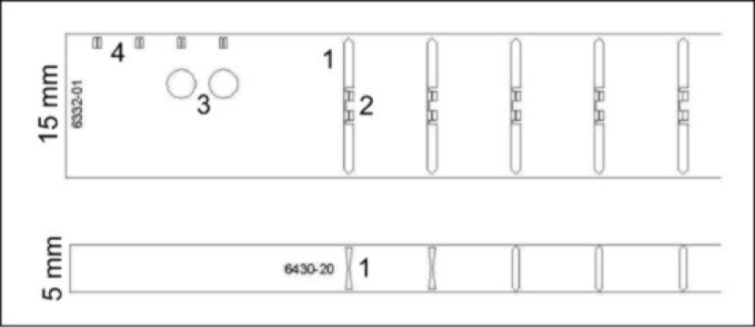
For modules with segmented wires they are also used at the inner sector borders (see Fig. 6). On both ends they have precision holes for the fixation and pads with 50 m slits for the alignment relative to an external reference wire. The gold-plated copper pads for the anode wire positioning and fixation have a complicated structure. There are short parts for the wire positioning in 50 m slits and long parts for soldering, one for the anode wire and one for either the connection to the HV board or for the corresponding thick wire in an insensitive module section (see Fig. 6). All four parts are connected electrically by thin bridges which prevent heat transfer when the second wire is soldered.
In order to prevent electrostatical instabilities due to slight module deformations, the free wire length must not exceed 60 cm. In cases where the distance between the broad strips is larger than that, an appropriate number of narrow support strips is equidistantly inserted.
Glue:
Epoxy is used to glue the foils to each other, to glue the wire support strips and to glue the end-pieces to the foils. As the outgassing of the epoxy is a potential source of chamber aging, Stycast 1266A, an epoxy with very low outgassing is chosen [19].
To improve the electrical contact between the foil layers, dots of conductive silver-loaded epoxy are distributed every 30 cm along the cell structure.
Wires:
The anode wires are gold-plated tungsten wires of 25 m diameter. The wire tension is 505 g, and the elasticity limit is 130 g.
Thick copper/beryllium wires of 75 m diameter are used for the signal propagation from sensitive inner module sectors to the high voltage board and the signal read-out at the module end (see Fig. 6). The large wire diameter prevents significant gas amplification at the nominal operating voltages. Both wire types are connected by soldering them to the wire support strip. The thick wires are strung with the same tension as the thin ones to balance the forces on the strips.
Solder Tin:
A halogen-free solder tin with a reduced solder-forming flux is used to avoid larger amounts of flux residuals around the solder point on the wire support strips. A mask positioned around the strip protects the cathode foil during soldering. The temperature of the soldering iron is required to be 280∘ C.
Carbon Fiber Rods:
Carbon fiber rods of 2 mm diameter are used to increase the stiffness of modules longer than about 2 m. Three rods are glued to both external module sides.
Aluminum Cover Foils:
A further improvement of the mechanical stability is reached by covering both module sides with aluminum foils of 10 m thickness.
3.4 Production Tools
In order to produce stiff honeycomb drift tube modules with precisely defined dimensions from foils which by themselves have no stability at all, the foils are handled using templates which force them to assume the nominal cell shape during assembly. Since the module length varies from 75 cm to 446 cm, a modular template system is designed. The complex parts at both ends and in the center, where the strips for the wire positioning and fixation are mounted, are machined from aluminum plates. The simpler parts in between are made of metal-reinforced epoxy using a casting technology. They have high precision and form stability but at much lower cost. In the template grooves there are holes through which under-pressure is applied which safely draws the foils into shape.
Each module production workplace consists of an upper and a lower template (Fig. 10). After placing the first set of foils, the wiring as well as wire tension and high voltage stability tests are performed on the open cells in the lower template. The upper template carries the set of top foils to be glued. The glue is distributed with a foam roller on the enhanced part of the foil profile in the upper template. A special mask made of a thin steel foil guarantees that the glue covers only the horizontal foil area and not the inner cell walls. Then the upper template is lifted by a crane, rotated and positioned above the lower template. With the help of positioning devices it is placed precisely onto the lower one thus closing a monolayer.
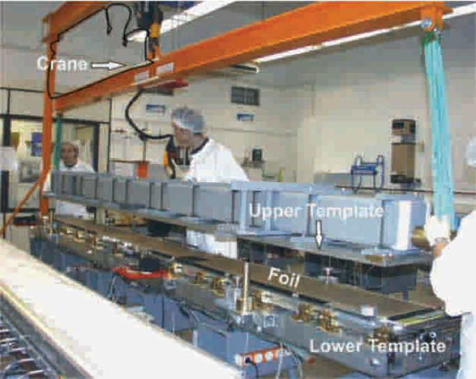
For each working place the template parts are assembled and aligned on a stable frame. Since the upper template has to be lifted and rotated, a movable crane is used for the long templates of the PC and TC modules. The template tolerances for the cell geometry and for the distance from the first to the last cell are better than 80 m. The alignment accuracy of the template parts is about 50 m.
3.5 Module Production
The main assembling steps are demonstrated in Fig. 4 for the first monolayer of a module. The module production starts with positioning the lower foil and the base plates in the lower production template. On both sides the end-pieces are glued to the foil and to the base plate giving a stable connection between both. In the first cell monolayer, wire supporting strips are glued starting 7 mm from the foil ends. The next steps are the wiring of the monolayer, the test of the wire tension and of the high voltage stability. If necessary, bad wires are replaced. Then, epoxy is distributed on the foil in the upper template and the layer is closed. After the curing of the glue, which lasts about three hours at room temperature, the procedure is repeated for the next monolayer. Finally, the carbon fiber rods and the aluminum cover foil are glued onto both module sides, and the high voltage boards are mounted.
To achieve the required throughput, the production was organized in different laboratories (NIKHEF Amsterdam, IHEP Beijing, Tsinghua Univ. Beijing, JINR Dubna, DESY in Hamburg and in Zeuthen). For the mass production standardized production templates, tools and the same detector materials were distributed to all institutes. In addition, standardized production procedures and quality tests have enforced coherent production conditions. In total 22 workplaces were installed in the clean rooms of the collaborating institutions, 17 of them for the production of PC- and TC-modules, and the others for the MC-modules.
With two shifts per day, a standard module with 4 monolayers can be built and tested within three days. The limiting factor is the curing time of the glue, but at each institute there were enough workplaces to avoid idle time. The production of the 978 modules could be finished within 15 months.
3.6 Quality Tests
The nominal wire tension is 50 5 g and wires outside of the tolerance limit have to be replaced. Before the monolayer is closed by the upper foil, the average dark current of all wires is measured in air using a high voltage of 2000 V. The allowed maximum current is 30 nA at low air humidity. Wires with larger currents are cleaned and have to be replaced if the current is still above the limit.
Each module production site operates a test stand for high voltage training and single wire test of the produced modules. The modules to be tested are put into a gas-tight box which is then flushed with an Ar/CO2 (50:50) gas mixture. The high voltage is ramped up to the nominal values of 1850 (2230) V for the 5 (10) mm drift cells. Only in rare cases the dark currents of single HV groups are so high that this has to be done in steps. Wires which after 12 hours at nominal HV still show dark currents A are considered unusable and are disconnected.
After the training, the analog signals from all wires are checked. This is done using either a cosmic particle trigger setup or a radioactive source together with an oscilloscope and allows to identify dead and noisy wires. Of the 112 674 wires in the Outer Tracker 482 are disconnected because of shorts or excessive dark currents, 363 showed no signals, and 402 have noise rates kHz. This corresponds to a fraction of 1.1 bad wires.
The results of quality control during module production and testing are recorded in a document file which accompanies each module from the start of production till the installation in a chamber. A computer readable test sheet per module can be inspected via a graphical web interface and is used during data taking for data quality cross-checks.
4 Superlayer Structure and Assembly
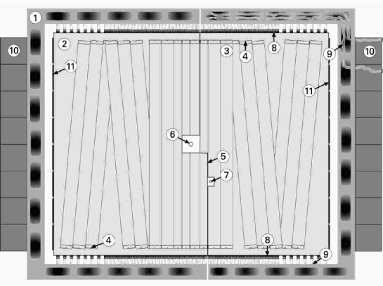
Table 1 summarizes the positions, dimensions and stereo layer configurations of all Outer Tracker superlayers. A schematical view of the structure which is typical for PC and TC superlayers is given in Fig. 11. It shows the division into two independent chambers across the proton and electron beam pipes. In their nominal position both chambers overlap to avoid detection inefficiencies for track reconstruction. The chambers are mounted on rails which allows for a movement perpendicular to the beam axis for easier installation and repair. Each chamber consists of two main components, the gas box and the outer steel frame.
4.1 Gas Box with Detector Modules
The gas box of a chamber fulfills several requirements:
-
•
It allows for a precise mounting of the modules in all stereo layers.
-
•
It provides a gas tight enclosure for the modules which is filled with the counting gas.
-
•
It places as little material as possible in the acceptance area of the detector.
The box consists of a C-shaped aluminum frame, a thin carbon fiber cap which closes the C and covers the modules in the overlap area, and two large sandwich panels closing the front and the back of the box.
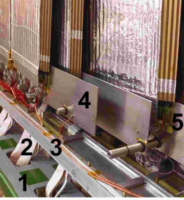
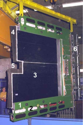
The picture of an open TC chamber in Fig. 12 shows the gas box frame together with plates on which the modules are mounted. By means of snap rings the plates are held in well-defined positions on large dowel pins which are anchored in the frame. This defines the z-positions of the stereo layers. On the plates there are many holes for pins and screws which are needed for vertical and horizontal module positioning and fixation.
The metal frame of the gas box has cut-outs into which so-called feed-through boards are inserted. These provide gas-tight connections of signal and HV lines from the modules inside to the outside of the gas box. On the outside, the ASD-8 boards are directly plugged onto the feed-through boards.
The large plates which close the gas box have to withstand large forces even at only 0.5 mbar overpressure inside the gas volume. On the other hand, the plates have to consist of light-weight material to minimize their contribution to the total material budget in the detector acceptance area. The plates are sandwich panels with an aramid paper core of hexagonal cell structure covered by two plates of carbon or glas fiber epoxy composite for the PC or TC chambers, respectively [30]. The cover plates with dimensions of about 2.5 3.2 for PC and 3.5 5 for TC chambers are glued on the gas box frame and additionally fixed by screws. The inner side of the plates is covered by a thin aluminum foil which provides an electrical shielding and prevents the contamination of the drift gas by outgassing products of the plate epoxy.
In the overlap area of both chambers end-caps made of a 1 mm thick carbon fiber epoxy composite material close the gas boxes. The right picture in Fig. 12 shows the cap of the PC2 chamber. Its structure is rather complicated since the cap has to enclose modules of six different stereo layers, to assure appropriate overlap and to follow the cut-out for the beam pipe. The caps were produced using templates which could be adjusted to the lengths and layer configurations of all chambers [31].
4.2 Outer Steel Frame
The outer steel frame is designed such that it can carry the weight of the gas box and the cables. The weight of a complete TC chamber is about three tons. The C-shaped steel frame is open towards the other chamber. Within the frame, the gas box containing the detector modules is mounted. The rectangular profile of the frame houses the large amount of signal cables, which are twisted pair cables connecting the ASD-8 front-end boards on top and bottom of the gas box with the TDC boards installed in crates at the vertical outer side of the frame. The holes in the steel profile seen in the left picture of Fig. 12 facilitate the insertion of cable bundles.
4.3 Assembly and Installation Steps
The chamber assembly starts with routing of prepared signal cable bundles in the outer frame from the position of the feedthrough boards to the corresponding TDC crates. Next, the gas box, still without front cover plate and overlap caps, is installed in the cabled frame. For module installation the chamber is brought to an upright position in a large dust-protection tent, in order to avoid extreme bending of the modules during installation.
The modules are installed layer by layer. After bringing all module fixation plates of a layer into their nominal positions, the modules are positioned and screwed on the top plates. On the bottom plates only the lateral position is fixed by a dowel pin in a precise slit in the module base plate, thus allowing for thermal expansion of the modules without buckling. Then, the signal cables are plugged and the high voltage cables are plugged soldered to the corresponding connectors on the inner sides of the feedthrough boards. Only after a careful check of all electrical connections and of the high voltage stability of the just installed modules the chamber assembly proceeds to the next stereo layer.
After all modules are installed, the front cover plate is glued and screwed to the gas box frame. The gas box is closed by mounting the cap structure in the overlap region with the other chamber. After checking the gas tightness of the assembled chamber it is equipped with ASD-8 amplifier boards on the feedthrough boards and with TDC boards in the crates on the outer frame. The low and high voltage distributions are installed as well. Hence all electronics can be commissioned using test pulses before the chamber is installed in the experiment.
Special support structures are used for transporting the chambers from the assembly to the experimental hall. In the HERA-B detector there is a rail for each superlayer from which both chambers are suspended. This allows chamber movement to and from the beam pipe which facilitates installation and maintenance of the Outer Tracker. Even for the largest chambers, the installation with the connection of the external cables and gas pipes takes no longer than a day.
4.4 Description of the Detector Geometry
In order to achieve a maximum of detector hermeticity with a minimum amount of material, the OTR detector geometry became rather complicated. The design of the superlayers and of the different module types was performed using a CAD system. The information on module and superlayer types as well as their geometrical description is stored in a data base. For the Monte Carlo simulation with GEANT [32], in addition to the geometrical data, all material properties of gas boxes and detector modules are taken into account. In total about 2500 different detector volumes are described, which are the module sectors (see Fig. 3).
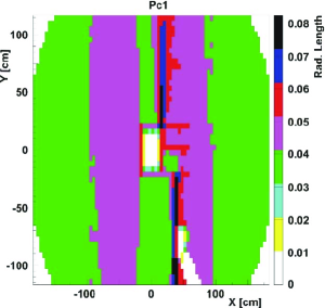
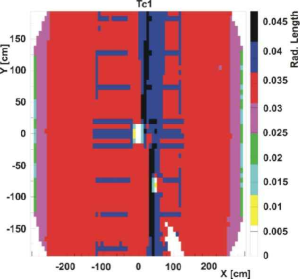
In Fig. 13 the material distribution is shown in terms of radiation lengths for the PC1 and TC1 superlayers. On average PC1 has 4–5 % of a radiation length, TC1 only 3–4 %.
Most of the material is concentrated in the overlap region of both chambers of each superlayer. In the area of TC1 for the 5 mm modules the wire support strips are visible. These areas are rather broad due to staggering of the strips within a module and the inclination of the stereo layers. Summing up the material contributions of all 13 superlayers, one gets about 0.4 radiation lengths on average and about 0.7 radiation lengths in some overlap areas of the chambers.
With the changed physics programme of HERA-B for the 2002 run the reconstruction efficiency for decays was of minor importance. It was found to be more crucial to reduce the background in the ECAL from secondary interactions in the magnet. As a consequence, the superlayers MC2–MC8 were removed from the detector which reduced the average material contribution of the Outer Tracker to 0.3 radiation lengths.
5 Gas System
The drift velocity of the counting gas has to be large because of the 96 ns time distance between bunches and the requirement to register events within this time. With a gas mixture containing a sufficient fraction of the fast gas component CF4, drift velocities of up to 150 m/ns are reached [33]. After studies of aging and etching properties with different gas mixtures like CF4/CH4, Ar/CF4/CH4 and Ar/CF4/CO2 [17], the latter mixture was chosen with a volume ratio of 65 /30 /5 .
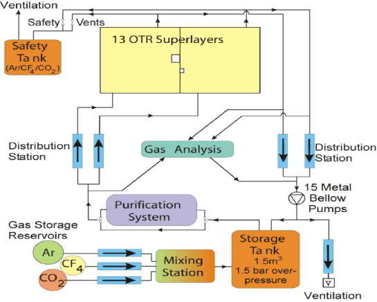
The total volume of all OTR chambers is about 22 m3. Because of the high cost of CF4 and also for environmental reasons, it is necessary to use a closed-loop gas system. The block diagram in Fig. 14 shows the functionality. The circuit consists of the following components: A 1.5 m3 storage tank where fresh gas coming from the mixing station is added to the circulation, the purification system, the distribution station which regulates the gas flow into the 26 chambers, and the pump station with 15 metal bellow pumps which circulate the gas. Both, gas flow and pressure are regulated and controlled with help of a programmable logic controller for the pressure transducers and mass flow controllers. The flow rate through the system is 20 m3/h, i.e. almost one volume exchange per hour. The gas enters a chamber through a distribution pipe at the bottom, flows through the cells of the modules, and leaves the gas box at the top. In order to minimize air intake through leaks in the gas boxes, the pressure in all chambers is kept at 0.5 mbar above atmospheric pressure. A safety tank filled with counting gas is acting as a buffer volume to minimize air intake in an alarm situation when the regulation is switched off and the chambers open to the outside via safety valves and safety tank. A detailed description of the gas system and its performance is given in [34].
Gas Storage and Mixing:
There are two 450-liter gas storage reservoirs filled with liquid Argon and with CO2, respectively, and a 600-liter tank for CF4. The gases flow into the mixing station in ratios controlled by gas flow regulators and then into the storage tank. In case of the first fill or for a longer shut-down period, a cheaper Ar/CO2 mixture is used to remove the air or to prevent that air enters the closed-loop system. With addition of the CF4 component one obtains the proper working gas mixture within several days. During data taking about 0.5 to 2 fresh gas per volume exchange is continuously added to the circulating gas. This results in a CF4 consumption of about 400 kg/month. The required tolerances for the gas composition are 651, 301 and 50.2 for Argon, CF4 and CO2, respectively.
Purification Station:
Before the gas is distributed to the different chambers, it is purified by removing oxygen and water. There are two regenerable purifier stations installed, both containing 60 kg of catalyst R3-11G [35]. While one of them is in operation, the other station is excluded from the closed-loop circuit for regeneration. About every 10 days the stations are switched. This guarantees a continuous gas purification keeping the oxygen content below 200 ppm and the water level below 20 ppm. Mainly due to residual air in the system and because of small leaks, there is a non-negligible fraction of nitrogen in the counting gas. The nitrogen level is kept below 2000 ppm by continuously venting a small fraction of the circulating gas and by adding a corresponding amount of fresh gas.
Trace contaminants in the counting gas were suppressed by strictly avoiding the use of outgassing materials in fittings, seals, pumps etc. Stainless steel and flexible metal tube piping was used throughout the system.
Gas Analysis for Quality Control:
The system continuously analyses the gas by measuring the fractions of the three main components and of certain impurities like oxygen, nitrogen and water. The common input after purification and all output lines from the 26 chambers can be connected via a programmable switch to the gas analysis station which consists of a gas chromatograph, an oxygen meter and a moisture meter. Each measurement takes about 10 minutes, i.e. after 4.5 hours a given line is measured again.
6 Summary
The Outer Tracker of the HERA-B experiment provides 90 % solid angle coverage in the center-of-mass system and is capable of recording up to 200 charged particle tracks every 96 ns.
In total 13 superlayers, each consisting of two individual planar drift chambers, were assembled and installed in three areas of the experiment: 7 inside the magnet, 4 between magnet and RICH, and 2 in front of the electromagnetic calorimeter. The stereo layers inside each chamber are composed of honeycomb drift tube modules. Module assembly from folded Pokalon-C foils results in a close-packed hexagonal drift cell structure. The technique of installing anode wires into open drift cells facilitates also longitudinal wire segmentation which is needed for limiting the occupancy close to the proton beam. Chamber aging, observed with prototype modules at high hadron fluxes, was cured by coating the cathode foils with thin layers of copper and gold, and by a proper drift gas. In total 978 detector modules with about 113000 electronics channels have been built. Two thirds of the modules have 5 mm diameter drift cells, the cell size in the others is 10 mm. Over a period of 15 months module production proceeded in parallel at six different laboratories, using the same tools, materials, and instructions. The initial fraction of bad channels was 1.1 %.
The honeycomb drift tube modules offer clear advantages in terms of operational safety, cathode aging, and easy mechanical handling. Although made of light material, the total amount of scattering material was on average about 0.4 radiation lengths in the fiducial volume of the detector. For the 2002 run this was reduced to 0.3 radiation lengths by removing chambers from the magnet.
For the 26 chambers of the Outer Tracker, with a total volume of 22 m3, a closed-loop gas system was built. It allows to regulate the flow, to control the pressure of the Ar/CF4/CO2 (65:30:5) gas mixture in all chambers, and to purify the gas.
During its operation from December 2001 until March 2003, the Outer Tracker of HERA-B worked well, as will be described in more detail in a forthcoming paper on OTR performance [12].
In conclusion, it has been shown that a large tracker can be efficiently built and safely operated under high radiation load at a hadron collider.
Acknowledgements
We thank our colleagues of the HERA-B Collaboration who made in a common effort the running of the detector possible. The HERA-B experiment would not have been possible without the enormous effort and commitment of our technical and administrative staff. It is a pleasure to thank all the teams at different sites involved in prototype chamber development, in module design and production, in construction and assembling of superlayers, and in the design and realization of the gas system.
We express our gratitude to the DESY laboratory for the strong support in setting up and running the HERA-B experiment. We are also indebted to the DESY accelerator group for the continuous efforts to provide good beam conditions.
References
- [1] T. Lohse et al., HERA-B: An Experiment to Study CP Violation in the B System Using an Internal Target at the HERA Proton Ring, Proposal, DESY-PRC 94/02 (1994).
- [2] E. Hartouni et al., HERA-B: An Experiment to Study CP Violation in the B System Using an Internal Target at the HERA Proton Ring, Design Report, DESY-PRC 95/01 (1995).
- [3] K. Ehret et al., Nucl. Instr. and Meth. A 446 (2000) 190.
- [4] C. Bauer et al., Nucl. Instr. and Meth. A 447 (2000) 61.
- [5] Y. Bagaturia et al., Nucl. Instr. and Meth. A 490 (2002) 223.
- [6] A. Gorisek et.al., Nucl. Instr. and Meth. A 518 (2004) 590.
- [7] M. Bruschi et al., Nucl. Instr. and Meth. A 461 (2001) 332.
- [8] Yu. Gilitsky et al., Nucl. Instr. and Meth. A 461 (2001) 104.
- [9] Nucl. Instr. and Meth. A 515 (2003) 126, 132, 140, 146, 152, 185, 202, 242.
- [10] HERA-B: Report on Status and Prospects October 2000, DESY-PRC-00-04 (2000).
- [11] H. Albrecht et al., (HERA-B Outer Tracker Group), Nucl. Instr. and Meth. A 541 (2005) 610.
- [12] H. Albrecht et al., (HERA-B Outer Tracker Group), to be submitted to Nucl. Instr. and Meth..
- [13] H. van der Graaf et al., Nucl. Instr. and Meth. A 307 (1991) 220; F. Bakker et al., Nucl. Instr. and Meth. A 330 (1993) 44.
- [14] H. P. M. Wirtz, Diploma Thesis, PITHA 93/6, RWTH Aachen (1993); A. Armbruster, Diploma Thesis, PITHA 94/40, RWTH Aachen (1994); J. F. Schottmueller, Diploma Thesis, PITHA 94/41, RWTH Aachen (1994).
- [15] Bayfol VP KL 3-1500, Bayer AG, D-51373 Leverkusen, Germany
- [16] LONZA-Folien GmbH, D-79576 Weil am Rhein, Germany.
- [17] H. Albrecht et al., Nucl. Instr. and Meth. A 515 (2003) 155.
- [18] K. Berkhan et al., Nucl. Instr. and Meth. A 515 (2003) 185.
- [19] M. Capeáns, Nucl. Instr. and Meth. A 515 (2003) 73.
- [20] APVV Angewandte Plasma-, Vakuum- und Verfahrenstechnik GmbH, D-45307 Essen, Germany.
- [21] ILFA Feinstleitertechnik GmbH, D-30559 Hannover, Germany.
- [22] Kunststoffverarbeitung Tautenhahn, D-89250 Senden, Germany.
- [23] Emerson Cuming, B-2260 Westerlo, Belgium.
- [24] EPOXY Produkte GmbH, D-64658 Fürth, Germany.
- [25] California Fine Wire Company, Grover Beach,CA 93433-0446, USA.
- [26] Little Falls Alloys Inc., Paterson, NJ 07501, USA.
- [27] Küppers Metallwerk GmbH, D-53115 Bonn, Germany.
- [28] Comat Composite Materials GmbH, D-67663 Kaiserslautern, Germany.
- [29] Alfol-Aluminiumfolien, D-31606 Warmsen, Germany.
- [30] HEXCEL Composites, B-4840 Welkenraedt, Belgium.
- [31] Lufthansa Technik AG, D-22313 Hamburg, Germany.
- [32] Program GEANT, Detector Description and Simulation Tool, CERN Program Library W5013 (1994).
- [33] O. Grimm, Diploma Thesis, University Hamburg (1998).
- [34] M. Hohlmann, Nucl. Instr. and Meth. A 515 (2003) 132.
- [35] BASF AG, D-67056 Ludwigshafen, Germany.