Surface state photonic bandgap cavities
Abstract
We propose and analyze a new type of a resonant high- cavity for lasing, sensing or filtering applications, which is based on a surface states of a finite photonic crystal. We demonstrate that such the cavity can have a factor comparable with that one of conventional photonic band-gap defect mode cavities. At the same time, the distinguished feature of the surface mode cavity is that it is situated directly at the surface of the photonic crystal. This might open up new possibilities for design of novel photonic devices and integration of photonic circuits.
pacs:
42.70.Qs, 42.25.Bs, 42.60.DaPhotonic crystals have attracted ever increasing attention in the last decade due to their unique properties and possible applications in future generation of optical and photonic devices like light emitting diodes, delay lines, waveguides and lasers joannopoulos ; Sakoda . The lasing effect has been demonstrated for variety of photonic crystal structures including bandgap defect mode lasers defect-mode , distributed feedback lasers feedback , and bandedge lasers bandedge . High- photonic bandgap cavities find their potential application in all-optical networks and photonic chips jon ; Noda . In this Letter we present a new type of a photonic bandgap cavity utilizing a surface state residing on the surface of a photonic crystal, which can be used for lasing, sensing or filtering applications. We demonstrate that a weak coupling of the resonant modes of the cavity with the outgoing radiation results in a strongly enhanced intensity of an electromagnetic field on the surface of the photonic crystal and leads to the ultra-high cavity factor.
Surface states reside at the interface between a photonic crystal and open space, decaying both into the crystal and air joannopoulos . An unmodified surface of a semi-infinite photonic crystal does not normally support the surface state. The surface state appears in the band-gap of the photonic crystal when the boundary of the photonic crystal is modified by, e.g., truncating the surface rods, shrinking or increasing their size, or creating more complex surface geometry joannopoulos ; Mendieta ; Zhang ; Elson ; we-PRB-2005 . It is important to emphasize that the surface mode residing on the infinitely long boundary of a semi-infinite crystal represents a truly bound state with the infinite lifetime and factor, and consequently does not couple with the incoming/outgoing radiation.
In our recent work we-PRB-2005 we have demonstrated that when the translational symmetry along the boundary of the semi-infinite crystal is broken, the surface mode turns into a resonant state with a finite lifetime, which can be utilized for lasing and sensing applications. The main purpose of the present Letter is to propose and analyze a structure that can be used for experimental realization of a high- surface state cavity in the bandgap photonic crystal. To identify the surface state resonant modes and compute their quality factors, we apply a novel computational approach based on the two-dimensional (2D) recursive Green’s function technique we-PRB-2005 . Using this technique, the intensity distribution of the electromagnetic radiation is computed in the frequency domain on the basis of the the Green’s function of the photonic structure that is calculated recursively by adding slice by slice on the basis of Dyson’s equation. In order to account for the infinite extension of the structure both into air and into the space occupied by the photonic crystal we make use of the so-called ”surface Green’s functions” that propagate the electromagnetic fields into (and from) infinity.
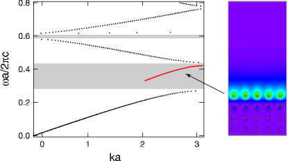
We study a semi-infinite square-lattice photonic crystal composed of dielectric rods (, diameter , is a lattice constant) in the air background. This structure has a fundamental bandgap for the TM-polarization in the interval joannopoulos , see Fig 1. To modify the surface we place rods of a reduced diameter on the infinitely long surface of a semi-infinite photonic crystal. This configuration supports one surface mode whose dispersion relation along the surface is illustrated in Fig. 1. The inset to Fig. 1 shows the intensity of the -component of the electromagnetic field in the surface state. The field is strongly localized at the surface rods and quickly decays both into the bulk of the photonic crystal and into air.
In order to provide a coupling between the surface state and incoming/outgoing radiation we consider a semi-infinite photonic crystal structure containing only a finite number of the surface rods of the reduced diameter . These rods define a resonant cavity situated at the surface of the photonic crystal as illustrated in the inset to Fig. 2 for the case of .
Our calculations are performed in the supercell geometry that infinitely extends into the air region to the left and into the bulk of the photonic crystal to the right (see Ref. [we-PRB-2005, ] for details). In the transverse direction (i.e. in the direction parallel to the surface) we utilize the cyclic boundary condition. In our calculation the supercell consists of unit cells in the transverse direction. Because of the rapid decay of the field intensity into the bulk, this choice is proven to be sufficient to ensure that the neighboring supercells are well isolated from each other.
In order to calculate the factor of the structure at hand, we illuminate the surface by an incidence wave (that excites the surface modes) and compute the intensity of the field distribution. The factor, defined as =2*(stored energy)/(energy lost per cycle), then can be expressed in the following form Sakoda ; we-PRB-2005 :
| (1) |
where characterizes the energy stored in the system (TM-polarization) and the integral over is the incoming energy flux. It should be stressed the value of the factor at resonance depends on the coupling of the surface state modes with the outgoing radiation, and thus is independent of the incidence angle of the incoming wave.
Note that the calculated field distribution includes the contributions from both the surface mode (exited by the incident light), and the incident and reflected waves. This leads to a nearly constant off-resonance background in the dependence that is caused by the contribution of the incident and reflected waves in the total field intensity in Eq. (1). To remove this background we calculate the factor of a structure without surface states. We choose this structure as a semi-infinite photonic crystal with all identical rods, which is known not to support surface modes joannopoulos . Then the obtained value is subtracted from the calculated value of the factor of the system under study we-PRB-2005 .
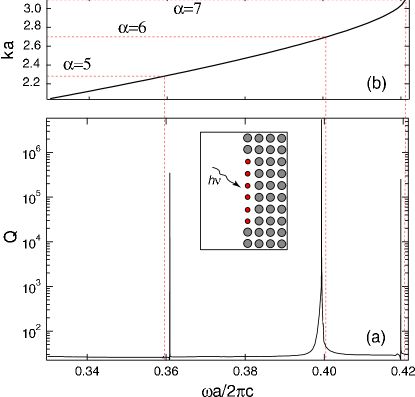
Figure 2 shows a factor of the resonant cavity as a function of the frequency of the illuminating light. In the given frequency interval there are three cavity modes with the factors of the order of . (Note that above values might underestimate the actual theoretical factors obtained within present 2D calculations, because even finer frequency steps in the vicinity of the resonances are required for better resolution of the factors). The calculated values of the factors are comparable to those predicted and achieved in defect mode bandgap cavities defect-mode ; Noda and in whispering-gallery trajectories cavities Slusher_1992 ; Gayral ; we-JAP-2003 ; Vahala . It is expected however that in actual photonic structures realized typically in a slab geometry, the factor will be reduced due to the radiative decay in the direction perpendicular to the plane of the photonic crystal Noda (which has not been accounted for in the present 2D calculations).
Let us now analyze the positions of the calculated resonance peaks. The structure at hand can be considered as a conventional Fabry-Perot resonator whose resonant wavelengths are given by , with the wavevector
| (2) |
where is the mode number and is the width of the cavity ( in the present case). For the photonic crystal under study the surface state exists only in a limited frequency interval, (see the dispersion relation for the surface state in Fig. 1). It follows from this dispersion relation that all the modes given by Eq. (2), except are situated outside this interval. An estimation of the expected positions for the resonant peaks for the modes based on Eq. (2) and on the dispersion relation for the surface mode is shown in Fig. 2 where the discrepancy between the expected and calculated resonance frequencies does not exceed .
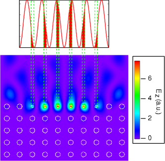
Figure 3 illustrates the intensity of the component of the electromagnetic field for the resonance mode . As expected, the field is localized in the cavity inside the rods, and the intensity dies off very quickly both to the open space and to the photonic crystal. The field intensity at different rods in the cavity is expected to be determined by the overlap of the th eigenstate of the Fabry-Perot resonator with the actual positions of the rods in the cavity. This overlap for the 6th mode is shown in Fig. 3, which agrees very well with the actual calculated intensity distribution pattern. Note that all the results reported in this Letter correspond to the case of rods (see inset to Fig. 2). We performed calculations for different numbers of rods and we always find an excellent agreement between the calculated and expected resonant frequencies as well as between the intensity distributions.
Recently, it has been demonstrated that a surface of a photonic crystal supporting a leaking surface mode can serve as a kind of antenna to beam the emitted light in a single direction, which may be used for integration of the photonic crystals with conventional fiber optics devices or lenses Moreno ; Kramper . The proposed surface mode photonic bandgap cavities, thanks to their unusual properties where the electromagnetic field resides directly on the surface, can also lead to new applications and novel integration schemes. These might include utilization of the surface state cavities for lasing and sensing applications as well as integration of the photonic crystal devices with e.g. whispering-gallery-trajectory microlasers that can be directly coupled to the surface mode cavities.
To conclude, we propose and analyze a novel high- cavity based on a surface state of a photonic crystal. The resonant cavity is localized directly on the surface row of the photonic crystal. This unusual property of the surface mode photonic bandgap cavities might open up new possibilities for design and integration of novel photonic devices for lasing, sensing and filtering applications.
References
- (1) J. D. Joannopoulos, R. D. Meade, and J. N. Winn, “Molding the Flow of Light”, (Princeton University Press, Princeton, 1995).
- (2) K. Sakoda, “Optical properties of photonic crystalls” (Springer, Berlin, 2001).
- (3) O. Painter, R. K. Lee, A. Scherer, A. Yariv, J. D. O’Brien, P. D. Dapkus, and I. Kim, Science 284, 1819 (1999).
- (4) M. Meier, A. Mekis, A. Dodabalapur, A. Timko, R. E. Slusher, J. D. Joannopoulos, and O. Nalamasu, Appl. Phys. Lett. 74, 7 (1999).
- (5) S.-H. Kwon, H.-Y Ryu, G.-H. Kim, Y.-H. Lee, and S.-B. Kim, Appl. Phys. Lett. 83, 3870 (2003).
- (6) J. D. Joannopoulos, P. R. Villeneuve,and S. Fan, Nature 386, 149 (1997).
- (7) B.-S. Song, S. Noda, T. Asano, and Y. Akanane, Nature Materials 4, 207 (2005).
- (8) F. Ramos-Mendieta and P. Halevi, Phys. Rev. B, 59 15112 (1999).
- (9) X. Zhang, L.-M. Li, Z.-Q. Zhang, and C. T. Chan, Phys. Rev. B, 63 125114 (2001).
- (10) J. M. Elson and K. Halterman, Opt. Express 12, 4855 (2004).
- (11) A.I. Rahachou, and I.V. Zozoulenko, to appear in Phys. Rev. B (arxiv:physics/0504088).
- (12) S. L. McCall, A. F. J. Levi, R. E. Slusher, S. J. Pearton, and R. A. Logan, Appl. Phys. Lett. 60, 289-291 (1992).
- (13) B. Gayral, J. M. Gérard, A. Lemaître, C. Dupuis, L. Manin, and J. L. Pelouard, Appl. Phys. Lett. 75, 1908-1910 (1999).
- (14) A. I. Rahachou and I. V. Zozoulenko, J. Appl. Phys. 94, 7929 (2003); A. I. Rahachou and I. V. Zozoulenko, Applied Optics 43, 1761 (2004)
- (15) D. K. Armani, T. J. Kippenberg, S. M. Spillane and K. J. Vahala, Nature 421, 925 (2003).
- (16) E. Moreno, F. J. García-Vidal, and L. Martín-Moreno, Phys. Rev. B 69, 121402(R) (2004).
- (17) P. Kramper, M. Agio, C.M. Soukoulis, A. Birner, F. Müller, R. B.Wehrspohn, U. Gösele, and V. Sandoghdar, Phys. Rev. Lett. 92, 13903 (2004).