SUMMARY OF EXPERIMENTAL STUDIES, AT CERN, ON A POSITRON SOURCE USING CRYSTAL EFFECTS
Abstract
A new kind of positron sources for future linear colliders, where the converter is an aligned tungsten crystal, oriented on the axis, has been studied at CERN in the WA103 experiment with tertiary electron beams from the SPS. In such sources the photons resulting from channeling radiation and coherent bremsstrahlung create the pairs.
Electron beams, of 6 and 10 GeV, were impinging on different kinds of targets: a 4 mm thick crystal, a 8 mm thick crystal and a compound target made of 4 mm crystal followed by 4 mm amorphous disk. An amorphous tungsten target 20 mm thick was also used for the sake of comparison with the 8 mm crystal and to check the ability of the detection system to provide the correct track reconstruction. The charged particles coming out from the target were detected in a drift chamber immersed partially in a magnetic field. The reconstruction of the particle trajectories provided the energy and angular spectrum of the positrons in a rather wide energy range (up to 150 MeV) and angular domain (up to 30 degrees). The experimental approach presented in this article provides a full description of this kind of source. A presentation of the measured positron distribution in momentum space (longitudinal versus transverse) is given to allow an easy determination of the available yield for a given momentum acceptance. Results on photons, measured downstream of the positron detector, are also presented. A significant enhancement of photon and positron production is clearly observed. This enhancement, for a 10 GeV incident beam, is of 4 for the 4 mm thick crystal and larger than 2 for the 8 mm thick crystal. Another important result concerns the validation of the simulations for the crystals, for which a quite good agreement was met between the simulations and the experiment, for positrons as well as for photons. These results are presented after a short presentation of the experimental setup and of the track reconstruction procedure.
keywords:
Channeling , Coherent Bremsstrahlung , Tungsten crystal , Relativistic Electrons , Gamma radiation , PositronsPACS:
07.77.Ka , 61.80.Fe , 52.59.-f , 61.85.+p, , , , , , ††thanks: presently at FNAL, Batavia, IL, USA , , , , , , , ††thanks: presently at Wayne State University - Cornell, Ithaca NY, USA , , , , , , , , , , , , , , ,
1 Introduction
Linear electron-positron colliders will be the privileged tool for studying physics in the TeV energy region. To overcome the decrease of the annihilation cross section, very large currents both in and in will be needed. The conventional positron source consists in an amorphous target of heavy metal, hit by a primary electron beam. Photons, which are produced by bremsstrahlung, are converted in the same target into pairs resulting in an electromagnetic shower. The thickness of the target is chosen to maximize the number of the positrons in the energy and angular domain of acceptance of the downstream matching system installed before the damping ring. Such positrons represent only a small fraction of all charged particles created in the target. This is due to their wide energy and angular spread, which comes from the photon emission and pair production processes and, above all, from multiple scattering of charged particles. Therefore a very intense primary electron beam is needed to achieve the desired positron beam current.
In the high energy region, the basic processes involved in the shower development are considerably enhanced in the oriented crystals, as compared with corresponding amorphous media. The most pronounced effects take place at the orientation where the electrons are incident along the major axes of the crystal. At such orientation, the incident electrons are exposed to the highest mean electric field provided by the atomic rows [1]. The enhancement depends on the particle energy and the crystal orientation (see [2] for further details concerning electromagnetic processes in crystals). Therefore, the replacement of the conventional positron target by a crystal is expected to improve the efficiency of the positron source.
When the energy increases, the coherent (crystal) effects become noticeable first in radiation, while their contribution to the pair production is still negligible. For example, the radiation intensity caused by the electric field of the -axis of a tungsten crystal exceeds that of the conventional bremsstrahlung starting with electron energies 1 GeV [1]. For the same crystal, the coherent contribution to the pair production starts to exceed that of the standard (Bethe-Heitler) mechanism at photon energies 22 GeV. For lighter crystals, the corresponding value of turns out to be several times larger than for tungsten. An incident electron energy of several GeV is foreseen for an efficient positron source. Then the pair production process proceeds in a crystal as in the corresponding amorphous medium. The enhancement of radiation from initial electrons is thereby the main crystal effect in the energy region of interest. According to theoretical estimates (see, e.g. [1]), the effective radiation length in a tungsten crystal becomes smaller than the conventional radiation length by the factor of 4.2 at 4 GeV and by the factor of 5.7 at 8 GeV. Alongside with the high power, the radiation at axial alignment is characterized by the softness of its spectrum. This leads to further increase in the number of emitted photons and in the number of produced positrons as compared with the amorphous target.
The description of the development of the electron-photon showers in an axially aligned crystal was elaborated in [3], [4], [5]. According to these papers (see also Fig. 1 in [6]), the electron energy is converted in a crystal target into photons over a thickness of several . Then at the depth most of the particles, including the initial electrons, are sufficiently soft to reduce the coherent contribution to the radiation to a level below the incoherent one. Therefore, the further development of the shower proceeds more or less in the same way for the crystal or amorphous type of the remaining part of a target. So, we come to the idea of a compound target, which consists of a crystal part of thickness about followed by an amorphous one [7]. We emphasize that the crystal part of a target serves as a radiator, and secondary charged particles are still not so numerous at this stage of the shower development. Therefore, only a small portion of the total energy loss is deposited in this part of the target, which considerably reduces the danger of its overheating.
In the construction of an intense positron source, the thermal issues are rather important. A substantial part (for example, more than 30 % in the JLC project [8]) of the primary beam power is dissipated and transformed into heat inside the target, mainly due to the ionization energy losses by the charged particles of the shower. As already observed in the SLAC Linear Collider (SLC) target, this causes serious thermal problems, which makes the actual limitation to the beam current. For crystals, where the ionization energy losses are practically not modified as compared with amorphous media, the thermal issues were considered in [4], [5] and, in detail, in [6]. It was found that, in the energy range under consideration, the positron yield at the optimal target thickness may be larger in a crystal case only by several percent. However, the amount of the energy deposition in a crystal turns out to be considerably lower (by a factor 2 for the JLC project, for instance) than in an amorphous target providing the same positron yield, while the Peak Energy Deposition Density (PEDD) is approximately of the same magnitude in both cases.
Recently the positron production in axially aligned single crystals was studied in two series of experiments performed at CERN [9] and KEK [10]. In both cases, the incident electron beam of different energies, up to 10 GeV, was aligned with the -axis of a tungsten crystal, which sometimes served as a crystal part of the compound target containing an additional amorphous tungsten part. Basing on the approach developed in [4] and [5], theoretical estimations were obtained in [11], which display a rather good agreement with the experimental results of [10], where only the positrons outgoing in the forward direction (i.e., with a vanishing transverse momentum) were registered for a discrete set of their longitudinal momentum values. However, to obtain a full description of the crystal-assisted positron source, the positron distribution in the whole momentum space, longitudinal and transverse, should be measured. This is done in the present experimental studies, where the energy and angular distributions of the positrons are obtained in a rather wide energy range (up to 150 MeV) and angular domain (up to 30 degrees).
2 The experimental setup
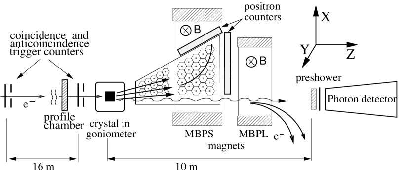
The experiment was installed on the X5 transfer line of the SPS West Hall at CERN. It used tertiary electron beams having energies between 5 and 40 GeV. After passing through trigger counters and profile monitors (delay chambers) the electrons impinge on the target. Photons and pairs are generated in this target. They go mainly in the forward direction and travel across the magnetic spectrometer made of a magnet (MBPS), with vertical magnetic field, inside which the drift chamber is placed. The drift chamber is completed by two positron counters, one on the wall away from the beam, one on the back wall (Fig. 1). The charged particles coming out from the Drift Chamber close to the forward direction are swept by a second magnet (MBPL) while the forward photons reach the photon detector made of a preshower and a calorimeter.
2.1 The beam
The SPS beam is made of 3.2 (resp. 5.2) second duration pulses with a 14.4 (resp. 16.8) second period for the 2000 (resp. 2001) summer runs. Each pulse contains electrons representing 99 % of the particles. This intensity value was currently reached at 6 and 10 GeV.
The channeling condition requires that the incident electron angle on the target be smaller than the Lindhard critical angle [12]; this angle is of 0.45 mrad at 10 GeV and for the orientation of the tungsten crystal. Taking into account the persistence of crystal effects at angles larger than the critical angle, the acceptance angle for the trigger was chosen equal to 0.75 mrad. This selects about 1% of the incident electrons. A trigger system made of scintillation counters, with a restricted angular aperture of 0.75 mrad, was installed upstream of the target. The trigger selection was improved off line by the informations provided by a proportional delay chamber. This delay chamber with horizontal and vertical grids, put at short distance from the target, provided informations on the lateral distributions of the incident electron beam. These informations served for beam control during the run and, as said above, were also used in the selection criteria. On Fig. 2 we represent the lateral distributions of the electron beam.
2.2 The targets
The crystal-assisted positron source can be an all-crystal target. However, coherent effects are mostly important at the beginning of the shower. In the following steps of the shower the particles have lower energies, larger angles and the crystalline effects are not important. Therefore, a compound target, made of a crystal as a primary radiator generating a large amount of photons and an amorphous disk where the photons are converted into pairs, has nearly the same advantages. In the experiment, four kinds of targets have been installed on a 0.001 degree precision goniometer:
-
•
a 4 mm thick crystal,
-
•
a 8 mm thick crystal,
-
•
a compound target made of 4 mm crystal followed by a 4 mm thick amorphous disk,
-
•
an amorphous disk 20 mm thick; this target was used in order to check the reconstruction efficiency with a number of positrons comparable to the one produced in a 8 mm thick aligned crystal.
Mosaic spreads of the crystals (root mean square disorientation angle of the crystalline domains) is measured by gamma-diffractometry at the Max-Planck Institute in Stuttgart- are slightly less than 0.5 mrad. The targets alignment was done using the data from the positron counters and from the photon preshower. The latter gives a signal proportional to the number of photons, which is maximum on axis position, as can be seen on the rocking curves (Fig. 3). The signal in the preshower is formed mainly by the two processes: conversion with the yield of two minimal ionizing particles (MIP) per photon and Compton scattering with the yield of one MIP per photon. The relative contributions of the processes depend on the emitted spectrum.
2.3 The positron detector
The positron detector consists in the drift chamber (DC) with hexagonal cells and positron scintillation counters. The DC is a quasi-plane detector with its largest dimensions in the horizontal plane and the smallest one, in the vertical plane. It presents two parts:
-
•
the first part (DC1), with a cell radius of 0.9 cm, is located mainly outside the magnetic field of the spectrometer. It allows the measurement of the horizontal exit angle, of the positrons.
-
•
the second one (DC2), with a cell radius of 1.6 cm, is immersed in the magnetic field. It allows the measurement of the horizontal positron (electron) momentum. Two values of the magnetic field are used: 1 and 4 kilogauss (KG), in order to investigate the whole energy region of interest, from 5 to 150 MeV.
In the drift chamber the wires are parallel to the magnetic field (vertical). The available space in the bending magnet (MBPS) restricts the vertical size of the chamber and therefore, the length of the wires (6 cm). With such short length, the border effect is significant. The drift chamber has metallic walls therefore these border effects lead to an increase of the gas amplification. In order to use the central part of the wires, two positron counters with a vertical size of 3 cm were used. That sets the vertical acceptance to degree for a distance target – counter of about 1 meter. The first counter is placed on the lateral side of the chamber and the other one on the back side. (see Fig. 1). Low energy positrons are more likely bent toward the side positron counter. Strictly speaking, for a many-track event, these counters told only that at least one track was hitting the central part of the wires but did not tell which one. The signal provided by the side counter gives a rather good indication on the low-energy positron yield. The signal wires in the drift chamber are made of gold-plated tungsten and the field wires of titanium. The drift chamber has 21 layers. The maximum horizontal angle being accepted is 30 degrees. The limited vertical size sets the overall acceptance to 6 % of solid angle. In order to reduce the multiple scattering for low-energy positrons the drift chamber is filled with an helium-based mixture He (90 %) + CH4 (10 %). The achieved coordinate resolution is about 500 micrometers. This leads to an angular resolution of 0.25 degree and a typical energy resolution of 0.6 MeV for both values of the magnetic field. Standard electronics associated to drift chambers is used. The data acquisition software is developed using KMAX system under Windows NT environment. The collected data is saved on a hard disk. The total amount of the raw data is approximately 3 GB.
2.4 The photon detector
The photon multiplicity is rather high: about 200 photons/event for a 8 mm thick crystal target oriented along its axis and 10 GeV initial electron energy. We measure only the average photon multiplicity and the total radiated energy, contained in a forward cone with maximum half angle of 4 mrad. For this goal the photon detector is made of:
-
•
a preshower made of a copper disk ( thick), followed by a scintillator. Two sizes of copper disks (3 and 6 cm in diameter, corresponding to a semi-angle aperture of 1.5 and 3 mrad respectively) have been used successively to look at the number of photons and at their angular distribution. The preshower gives information on the average photon multiplicity. As the number of photons varies more sharply than the radiated energy with respect to the crystal orientation, the preshower signal is used for the crystal alignment.
-
•
a ”spaghetti” calorimeter with thin scintillation fibers, giving the amount of radiated energy (see [13]). The preshower is in close contact with the ”spaghetti” calorimeter.


3 Analysis
3.1 The reconstruction procedure
The track reconstruction was done with the histogram method, modified to assign 3 parameters to each track. To avoid difficulties coming from the high rate of occupancy and complications from the non-uniform magnetic field in the first part of the drift chamber, the reconstructed trajectory was based on the informations from the second part of the chamber. The extrapolation back to the target has been operated using the measured values of the field. The trajectory of an electron or positron, projected on the horizontal plane, was parametrised as a circle with the following parameters: is the radius of the circle; are the coordinates of the circle center. To determine the track parameters, a minimum of 3 hits must be detected. Each hit may be represented by a small circle centered on the hit wire and the radius of which is proportional to the drift time. If n hits were detected in the drift chamber, the number of all possible tracks based on 3 hits each is , according to combinatorial analysis. The factor 8 comes from the two possible contact points between the track and the small hit circle, this choice being repeated 3 times. For example for the 20 mm target and 10 GeV incident electron the typical number of hits is near 50 and the typical number of reconstructed tracks is 4 – 5. All these tracks parameters are collected in three 2D-histograms: (), () and (). All the hit triplets produced by the same real track will give approximately the same values of parameters and hence will produce a peak on the histograms. The histogram peak position serve as a parameter seed for the fitting procedure. The candidate with maximal number of hits is selected and all the hits belonging to this candidate are removed from the further consideration. After that, the next track is chosen with the same procedure and this procedure is repeated as long as at least one candidate with 4 hits exists. For each track found the optimal set of parameters is calculated: the charge , the horizontal momentum and the horizontal angle with respect to the beam axis.
3.2 Reconstruction efficiency
We define a reconstruction efficiency as:
| (1) |
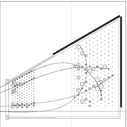
where is the number of reconstructed tracks, , the number of positrons passing through the chamber, i.e., crossing a minimum number of cells and where is taken for and for the due to the flatness of the drift chamber. This efficiency is determined by the simulations. It has been calculated with GEANT code [14]. For the case with high occupancy (20mm amorphous target and 10 GeV incident electron beam) it reaches 80% at large angles. However for the tracks with angles degrees (usually high positron momenta), this efficiency is reduced to 50 % due to the high occupancy. An example of the reconstructed tracks, per one event, is given in figure 4. The yield, as reported in the results, is defined as:
| (2) |
where is the number of measured positrons given by reconstruction, , the acceptance of the Drift Chamber in the horizontal and vertical planes. The acceptance is also derived from the simulations.
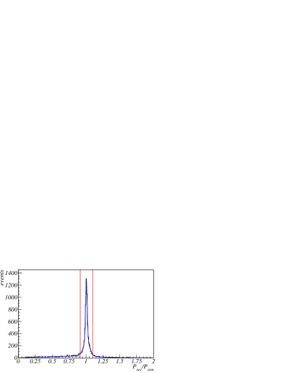
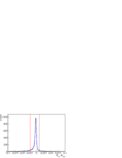
Among the reconstructed tracks only a part can be considered as “good tracks” corresponding to a proper evaluation of the positron momentum and angle. An illustration of the quality of track reconstruction is given in figures 5 and 6, which result from simulations, where the vertical cuts limit the domain of good tracks. Outside of these cuts, there are ”bad” reconstructed tracks with poor resolution in momentum or also fake tracks. Assuming that the contamination of bad tracks in the simulations and in the experiment is the same, this contamination is automatically corrected in equation (2).

3.3 Data selection
The experimental results were obtained using the following procedure.
-
•
The incident electrons were selected by the trigger counters. Additional off-line selection was made with the profile monitor (Fig. 2).
-
•
For further analysis only tracks with a positron-like curvature were selected.
-
•
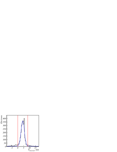
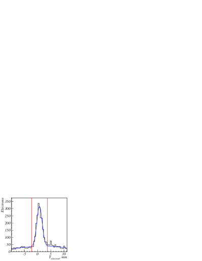
To reduce the background from the charged particles created outside the target (e.g. in the target supporting structure, in the drift chamber walls, etc.) the reconstructed track position on the target plane is limited within around the peak values, where is the RMS of the reconstructed position distribution.
-
•
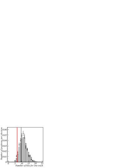
To reduce the rate of the fake tracks only tracks with the number of hits were selected. In Fig. 7 one can see that there is a reasonable agreement between the simulation and experimental data for the distribution of the number of hits for one track; hence simulation can be used safely to determine the efficiency.
-
•
The positron registration efficiency was determined for each energy and angular bin using the simulation. Such efficiency value is needed to evaluate the actual yield at the target exit. The shower development in the targets was simulated using an event generator “Shower Generation in Crystal” (SGC) taking into account the specific character of electromagnetic interactions in axially aligned crystals. The main features of SGC are given in [4],[5]. Note that SGC can be used to describe the shower development in amorphous targets as well.
A full description of the detector uses a GEANT code configuration.
The results on positrons presented hereafter are, henceforth, taking into account the reconstruction efficiency, i.e. the number of reconstructed positrons for each energy or angle bin was divided by the corresponding efficiency and detector acceptance.
The momentum resolution is depending on value. It is between 2 and 5 % for the tracks in the domain of interest ( MeV/c; degrees); the best resolution being for low momenta due to the larger curvature of the track. This momentum resolution has been determined from the comparison between the reconstructed and simulated momenta (see Fig. 5). The value of the momentum resolution has low impact on the shape of the measured histograms due to the larger energy bin width (5 MeV) with respect to this resolution. The momentum resolution is also considered in the simulations.
-
•
The detection efficiency, determined by simulations, was obtained for both values of the magnetic field. The data corrected by efficiency and detector acceptance for 1 and 4 KG magnetic field values were merged and the difference between the data and the simulations for the 20 mm amorphous target serves as an estimator of systematic errors (see section 4.4).
4 Results
The experimental results on the 20 mm amorphous target and on the 4 and 8 mm crystals in random orientation have been compared to the simulation with the GEANT based generator and to those obtained with the generator SGC. A good agreement was met between experiment and simulations in all the cases. That means that the apparatus and the reconstruction procedure worked quite well. Moreover, a good agreement was verified between GEANT and the SGC for the case of the amorphous target case (see Fig. 8).
4.1 Enhancement in photon production
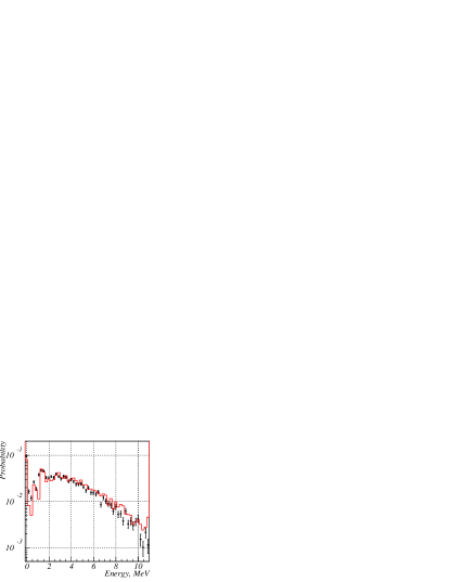
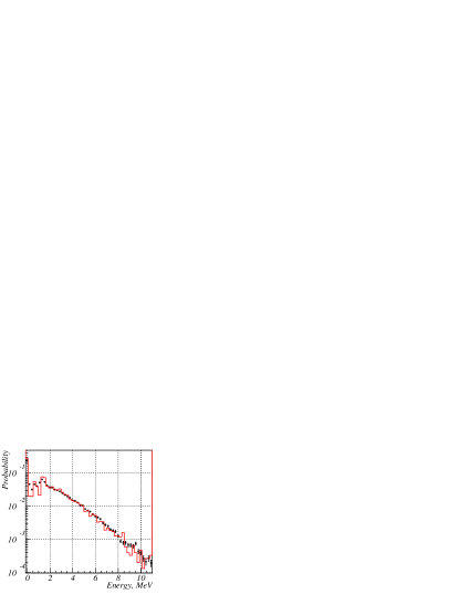
The preshower gives the average photon multiplicity in a forward cone as a function of the crystal orientation. On the axis of the tungsten crystal, the ultrarelativistic electrons radiate more photons than by conventional bremsstrahlung, as shown on the right rocking curve of figure 3. Correspondingly, the positron yield is enhanced (see left rocking curve of Fig. 3). In Figs. 9–10 we can see a good agreement between simulation and experiment concerning the preshower for 4 and 8 mm crystal, the incident electron energy being 10 GeV. In these figures we represent the spectrum of the energy lost in the scintillator by the charged particles, created by the photons in the converter. The first three peaks are corresponding to i) no interaction, ii) Compton scattering and iii) pair creation. All the results presented in Figs. 9–10 are normalized for one event. These results do not allow to extract the experimental photon spectrum, but serve as a check of the correctness for the photon part of the SGC generator.
4.2 Enhancement in positron production
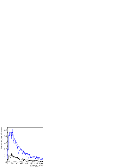
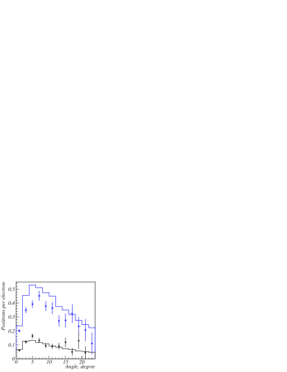
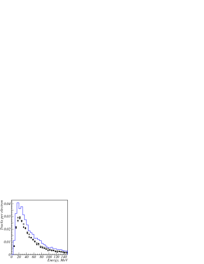
Typical energy and angular distributions are presented in Fig. 11 for the 4 mm thick crystal and amorphous targets. The energy of the initial electron is 10 GeV. Simulations and experimental data are presented on the same picture. The energy distribution concerns all positron angles up to 30 degrees, whereas the angular distribution concerns all energies more than 5 MeV; that means also high energies (more than 150 MeV) for which the discrepancy between simulation and experiment is somewhat larger. Precisely, these large momenta exhibit low angle values. In the energy domain of interest, for the positron sources ( MeV) the agreement is good between simulation and experiment. Moreover, if we compare the crystal and amorphous targets, an enhancement by a factor close to 4 is obtained for the oriented crystal. Similar considerations may be formulated for the case of the 8 mm crystal target for which:
-
•
an enhancement slightly larger than 2 is observed in positron production between the crystal and an amorphous target 8 mm thick, still for incident electrons of 10 GeV. This enhancement is present but slightly lower (than 2) when the electron incident energy is of 6 GeV.
-
•
almost identical results about the positron yields are obtained for a 8 mm ”all crystal” target and a compound target made of a 4 mm crystal followed by a 4 mm amorphous disk. Such results confirm the interest of compound targets for which the first part acts as a radiator and the second part as a converter to materialize the photons in pairs.
Results on the 8 mm target are represented in Fig. 12.
4.3 Presentation of the experimental results in the (,) space
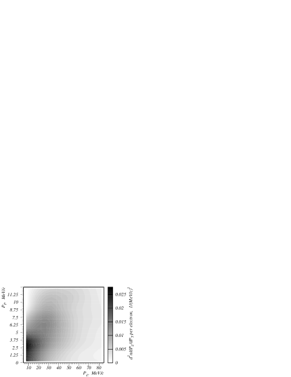
As the acceptance of the matching systems put after the positron target may be defined in the (,) space with the indication of the maximum accepted momenta in the longitudinal and transverse directions, we have chosen to represent the population of the reconstructed positron tracks in such diagrams. Fig. 13 corresponds to the 8 mm crystal target. Results are corrected by the reconstruction efficiency and the detector acceptance. It can be seen that the highest densities of positrons are contained in a domain defined by MeV/c and MeV/c. Suitable matching systems (adiabatic devices) which are presently considered for the future linear colliders [15] are presenting such kind of acceptance.
We also present these results, in (,) space, in the form of tables (tables 1 to 5) giving the number of positrons in some relevant (,) domains for all the targets. In those tables the simulations errors are mainly systematics and found to be near 5%. Experimental results are presented with the statistical errors. The numbers are corrected by the reconstruction efficiency and the detector acceptance. These tables where results from experiment and simulations are compared show that:
-
•
the expected positron yield may be determined accurately, provided the matching system has been precisely defined. The matching systems are usually characterized by the accepted energy domain and by the maximum transverse momentum; the latter depending on the maximum magnetic fields of the matching lenses.
-
•
the increase of the positron yield with the maximum longitudinal momentum for a given maximum transverse momentum is rather slow, showing that there is a predominance of soft positrons with crystal targets.
-
•
the accepted yield may be improved significantly by increasing the maximum transverse momentum. For a given energy domain, MeV/c the yield is improved by a factor between 1.6 and 2 when increasing the maximum transverse momentum from 4 to 8 MeV/c.
-
•
the discrepancies between simulations and experiment are within 10 to 25 % (for the worst case, i.e. the 8 mm target). This is not negligible but comparable with usual differences between phase space simulations and measurements.
4.4 Systematic errors
Various sources of systematic errors on the positron yield can be considered. They are discussed below.
Using the simulation, the influence of the beam angular spread was estimated to be negligible. The errors induced by the trigger selection were estimated applying a modified cut on the profiles given by the delay chamber: the error is 3%.
Systematic errors on the calibration “time-radius” of the drift chamber led to a 3% error on the results.
Measurements of the magnetic field contain errors which led, according to simulations, to an uncertainty of 4% on the positron momentum measurement.
Comparing the amorphous target simulations for the SGC and GEANT generators, a 5% systematic error was assigned to the generator induced uncertainties.
The main source of the systematic errors is in the estimations of the efficiency and fake track rate. This uncertainty has several sources: a difference between the real and assumed positions of the positron detector relative to the target; the charge collection dependence on the track multiplicity in the cell; the dependence of the gas multiplication factor on the coordinates along the wire; border effects in the drift chamber cell. Comparing the experimental results concerning the 20 mm amorphous target with the simulations using GEANT and SGC generators, the error was found to be equal to 8%.
The total systematic error is 10%.
Additional reliability checks were performed. It was checked that the results obtained with 1 and 4 KG magnetic field are the same in the region of the positron momentum available for both values.
The 20 mm amorphous target gives approximately the same occupancy in the positron detector as the 8 mm crystal target. The positron spectra for the 20 mm are in good agreement with the simulation, which proves the correct efficiency and fake track rate estimation for the case with the biggest track occupancy in the experiment. However it was found that the 8 mm oriented crystal produces 20% less positrons compared to the simulation prediction (Fig. 12). This could be the indication that the simulation in this case is less precise or that the experimental systematic errors are underestimated.
5 DISCUSSION AND CONCLUSION
The main results obtained in this experiment show:
-
•
a clear enhancement in photon and positron generations when comparing crystal and amorphous targets of the same thickness. This enhancement is close to 4 for 4 mm target and larger than 2 for 8 mm target with a 10 GeV electron beam. The enhancement is somewhat lower at 6 GeV.
-
•
a good equivalence between the results for 8 mm crystal and the compound target allows the use of the latter instead of the all-crystal, for thermal reasons.
-
•
a large number of soft positrons due to the materialization of soft photons. The channeling and coherent bremsstrahlung processes provide softer photons than classical bremsstrahlung. So an enhanced number of soft positrons due to the materialization of these soft photons is available. The practical interest is a better matching with known energy acceptances of currently used matching systems.
-
•
a good agreement between simulations and experiment for photons and positrons. This result validates the simulations based on crystal processes, permitting reliable simulations with different incident energies and crystal types (material, orientation, thickness). That is essential to optimize this kind of source.
We may add an additive argument for the use of crystal targets, due to investigations on the deposited energy in these targets [6]. It results from these calculations that even if the PEDD in crystal and amorphous targets giving the same yield is practically the same, the total deposited energy is much less in the crystal case. This set of arguments make this kind of positron source attractive. It justifies also the continuous interest in investigating such sources as it can be verified presently at KEK [16],[17].
6 Acknowledgments
The authors are indebted to Professors J.Lefrancois, F.Richard, A.Skrinsky for their appreciable support. We are grateful for the technical support in BINP, LAL and IPNL.
References
- [1] V. N. Baier, V. M. Katkov and V. M. Strakhovenko, Phys. Stat. Sol. B 133 (1986) 583.
- [2] V. N. Baier, V. M. Katkov and V. M. Strakhovenko, Electromagnetic Processes at High Energies in Oriented Single Crystals, World Scientific Publishing Co, Singapore 1998.
- [3] X. Artru, Nucl. Instr. Meth. B 48 (1990) 278.
- [4] V. N. Baier, V. M. Katkov and V. M. Strakhovenko, Nucl. Instr. Meth. B 103 (1995) 147.
- [5] V. N. Baier and V. M. Strakhovenko, Nucl. Instr. Meth. B 155 (1999) 403.
- [6] X. Artru, R. Chehab, M. Chevallier, V. Strakhovenko, Phys. Rev. ST Accel. Beams 6: 091003 (2003).
- [7] R. Chehab et al., Proceedings of IEEE 1989 PAC, March 1989, Chicago, IL .
- [8] T. Kamitani in ”Proceedings of the Mini-Workshop on Channeling Radiation Phenomena and Positron Production” KEK, KEK Proceedings 2002 26, March 2003.
- [9] X. Artru et al., Nucl. Instr. Meth. B 201 (2003) 243.
- [10] H. Okuno et al., Nucl. Instr. Meth. B 201 (2003) 259.
- [11] V. N. Baier and V. M. Strakhovenko, Phys. Rev. ST Accel. Beams 5: 121001 (2002).
- [12] D. S. Gemmel, Review of Modern Physics 46 (1974) 129.
- [13] V. Bellini et al., Nucl. Instrum. Meth. A 386 (1997) 254.
- [14] GEANT project page, http://wwwasd.web.cern.ch/wwwasd/geant.
- [15] R. Chehab “Positron sources”, CERN 94-01, Proceedings of CERN Accelerator School.
- [16] T. Suwada et al, Physical Review E 67 (2003) 016502.
- [17] M. Satoh et al, Nucl. Instr. Meth. B 227 (2005) 3.
| experiment | MeV/c | MeV/c | MeV/c |
|---|---|---|---|
| MeV/c | |||
| MeV/c | |||
| MeV/c | |||
| MeV/c | |||
| MeV/c | |||
| simulation | MeV/c | MeV/c | MeV/c |
| MeV/c | |||
| MeV/c | |||
| MeV/c | |||
| MeV/c | |||
| MeV/c |
| experiment | MeV/c | MeV/c | MeV/c |
|---|---|---|---|
| MeV/c | |||
| MeV/c | |||
| MeV/c | |||
| MeV/c | |||
| MeV/c | |||
| simulation | MeV/c | MeV/c | MeV/c |
| MeV/c | |||
| MeV/c | |||
| MeV/c | |||
| MeV/c | |||
| MeV/c |
| experiment | MeV/c | MeV/c | MeV/c |
|---|---|---|---|
| MeV/c | |||
| MeV/c | |||
| MeV/c | |||
| MeV/c | |||
| MeV/c | |||
| simulation | MeV/c | MeV/c | MeV/c |
| MeV/c | |||
| MeV/c | |||
| MeV/c | |||
| MeV/c | |||
| MeV/c |
| experiment | MeV/c | MeV/c | MeV/c |
|---|---|---|---|
| MeV/c | |||
| MeV/c | |||
| Me V/c | |||
| MeV/c | |||
| MeV/c | |||
| simulation | MeV/c | MeV/c | MeV/c |
| MeV/c | |||
| MeV/c | |||
| MeV/c | |||
| MeV/c | |||
| MeV/c |
| experiment | MeV/c | MeV/c | MeV/c |
|---|---|---|---|
| MeV/c | |||
| MeV/c | |||
| MeV/c | |||
| MeV/c | |||
| MeV/c | |||
| simulation | MeV/c | MeV/c | MeV/c |
| MeV/c | |||
| MeV/c | |||
| MeV/c | |||
| MeV/c | |||
| MeV/c |