Also at ]the Center for Optical and Electromagnetic Research, Zhejiang University, YuQuan, Hangzhou, 310027, P. R. China.
Surface-mode microcavity
Abstract
Optical microcavities based on zero-group-velocity surface modes in photonic crystal slabs are studied. It is shown that high quality factors can be easily obtained for such microcavities in photonic crystal slabs. With increasing of the cavity length, the quality factor is gradually enhanced and the resonant frequency converges to that of the zero-group-velocity surface mode in the photonic crystal. The number of the resonant modes with high quality factors is mainly determined by the number of surface modes with zero-group velocity.
pacs:
42.55.Sa, 42.70.QsOptical microcavities have attracted much attention due to their potential applications in many various fields, such as ultrasmall optical filters, high efficiency light emission diodes, low threshold lasers, nonlinear optics and quantum information precessing Noda et al. (2000a); Song et al. (2005); Qiu and Jaskorzynska (2003); Painter et al. (1999); Spillane et al. (2002); Michler et al. (2000). All applications require microcavities to confine light strongly and densely, that is, microcavities should have both a high-quality factor and small modal volume . Total internal reflection and/or Bragg reflection are generally used for light confinement. For the smaller cavity, is greatly reduced. One of the best approaches to resolve the problem is the extension of the Bragg reflection in a two-dimensional (2D) or a three-dimensional (3D) photonic crystal (PhC) Noda et al. (2000b). It has been also shown that extremely small-mode-volume high- microcavities can be realized by 2D PhC slabs Song et al. (2005); Yoshie et al. (2001); Akahane et al. (2003a); Ryu et al. (2003); Akahane et al. (2003b); Zhang and Qiu (2004), owing to strong optical confinement for both the in-plane and vertical direction.
Surface waves are propagating electromagnetic waves, which are bound to the interface between materials and free space. For dielectric interfaces, they usually do not exist on dielectric materials. However, due to the existence of photonic band gaps, it has been shown that dielectric PhCs may support surface waves for some cases, e.g., a truncated or deformed structure at the interface Joannopoulos et al. (1995). In the present letter, we study PhC microcavities utilizing surface modes with zero-group velocity. Though the concepts apply for all PhCs, for simplicity, only surface resonant modes in 2D PhC slabs are considered in this letter. These cavities are open cavities in the sense that one of the in-plane boundaries is exposed to exterior. Although the similar structure has been realized by Yang et. al. experimentally Yang (2004), the dependence of the quality factor and resonant frequency to the cavity length has not been analyzed yet.
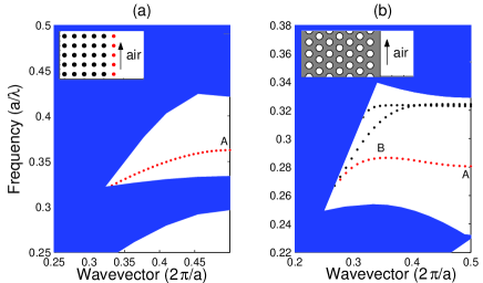
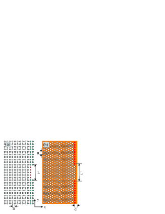
Let us first consider a 2D square PhC slab with dielectric rods in air. The permittivity of the rods is , the height of the rods is , and the radius of the rods is , where is the lattice constant. Surface defects at the interface are introduced by reducing the radius of rods (), the top view of which is illustrated in the inset of Fig. 1 (a). The dispersion relation for the reduced-radii rod-slab transverse magnetic (TM) surface modes is calculated using the 3D finite-difference time-domain (FDTD) method Taflove (2000) and is shown in Fig. 1 (a), where the shadow regions are the projected band structure for TM modes. It can be seen from Fig. 1 (a) that such a surface structure only supports one surface mode. Group velocity governed by for the surface mode is zero for the wave vector (Mode A). Suppose an optical microcavity that is composed by the 2D square PhC slab, as shown in Fig. 2 (a). The grey rods, acting as reflecting mirrors in the direction, are the same as those interior rods. The length of the cavity is denoted by . Surface modes can go through the central surface but are terminated by the reflecting mirror. Only the mode for obeying the Fabry-Perot condition (the round-trip accumulated phase is a multiple of , where is the phase shift associated with reflection from the boundary) will stay in the cavity for a long time, i.e., become a surface resonant mode. For such a microcavity, with no absorption by the material, the quality factor is mainly determined by the reflection loss at the interface between the surface defect rods and the mirror rods .
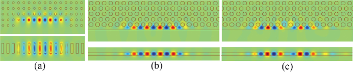
Quality factors and resonant frequencies of surface resonant modes are analyzed by the 3D FDTD method Taflove (2000) with a boundary treatment of perfectly matched layers Berenger (1994). We excite the surface mode with a Gaussian pulse and then monitor the radiative decay of the field. The frequencies and quality factors of the resonant modes are calculated using a combination of FDTD techniques and Padé approximation with Baker’s algorithm Guo et al. (2001). In Fig. 3 (a), we show the electric field cross sections of a high- surface resonant mode for the square PhC slab cavity with the length of . Figure 3 (a) depicts horizontal and vertical cross sections of the electric-field component at the center plane of third axis () and at the plane center of the surface defects, where the dotted line represents the position of the surface defect rods with . The mode has an angular frequency and quality factor , in which and (). It can be clearly seen from Fig. 3 (a) that the resonant mode is really governed by wave vector , which is consistent with what we analyzed above.
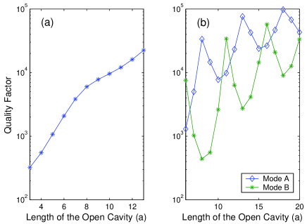
From Fig. 3 (a), one can see that the electric field is almost concentrated in the centers of the defect rods. We believe that the reflection phase shift is close to , which is roughly independent of the cavity length . Therefore, the cavity modes can be related to surface modes which satisfy , ( and is an integer). However, our results also show that the quality factor of the resonant mode corresponding to , i.e., zero-group-velocity surface mode, is order of magnitude larger than those of cavity modes with other vectors. values for such a cavity mode with different cavity length are shown in Fig. 4 (a). It can be seen from Fig. 4 (a) that gradually increases as the cavity length becomes larger. Our results also show, with increasing of the cavity length, that the angular frequency of the surface resonant mode converges to , corresponding to that with the zero-group-velocity surface mode in the PhC slab.
Let us next consider a triangular PhC slab with air holes extending through a high-index ( ) finite-height dielectric slab, the top view of which is shown in the inset of Fig. 1 (b). The holes have a radius of , while the high-index slab is of thickness . The distance between right boundary and the centers of the first right holes is . The dispersion relation for such a triangular PhC slab transverse electric (TE) surface modes is shown in Fig. 1 (b), where the shadow regions are the projected band structure for TE modes. One can see from Fig. 1 (b) that there exist three surface mode curves in the triangular PhC slab. For simplicity, we only consider the angular frequency between and , where there is one surface mode in a large region. Two zero-group-velocity surface modes (Mode A with and Mode B with ) can be found in our considered frequency region. Now, imagine an optical cavity composed by such a 2D triangular PhC slab, as shown in Fig. 2 (b). The reflecting mirrors in the direction are introduced by enlarging the radius of surface holes to , together with the dielectric background. Using the method mentioned above, we do find two high-quality-factor surface resonant modes with the cavity length of . One of the modes (corresponding to Mode A) has a resonant angular frequency , and another (corresponding to Mode B) is , . Figures 3 (b) and 3 (c) show the magnetic-field cross sections for the two resonant modes with the frequency of and , respectively. The upper and bottom figure represent the horizontal and vertical cross sections of the magnetic field at the center plane of third axis () and at the vertical plane (the distance between surface boundary and the plane is ), respectively.
Our results show that, when the cavity length increases, the frequencies of the resonant modes converge to those two surface modes with zero-group velocity. However, values fluctuate as the cavity length increases, as shown in Fig. 4(b), where the diamond line and the asterisk line represent the results for Modes A and B, respectively. As described in Ref. Ibanescu et al. (2005), should be enhanced when is a multiple of . Due to the complicated reflection interfaces, as seen in Fig. 2(b), the reflection phase shift is not close to for the both modes, different from the case of the square lattice. Furthermore, for the cavity length with numbers of lattice constant, is not anymore close to a multiple of for the Mode B with . Peaks of appear when is close to a multiple of . The positions of peaks for the Mode A are different with those for the Mode B, mainly arisen from the different wave vectors for the two resonant modes. reaches at when and is when . If the cavity length is further increased, values will again fluctuate but in average increasing.
In this letter, we study optical microcavities based on surface modes in PhCs. High quality factors can be obtained for microcavities based on zero-group-velocity surface modes. We also study the influence of the microcavity length to the quality factor and resonant frequency. It has been shown that, with increasing of the cavity length, the quality factor is gradually enhanced and resonant angular frequency converges to , corresponding to that for the zero-group-velocity surface mode in PhCs. The number of the resonant modes with high quality factors is mainly determined by the number of surface modes with zero-group velocity. It is well known that surface plasmons exist on a metal-dielectric interface. We believe similar ideas can be applied to a metallic structure to obtain surface resonant modes.
This work was supported by the Swedish Foundation for Strategic Research (SSF) on INGVAR program, the SSF Strategic Research Center in Photonics, and the Swedish Research Council (VR) under Project No. 2003-5501.
I References
References
- Noda et al. (2000a) S. Noda, A. Chutinan, and M. Imada, Nature (London) 407, 608 (2000a).
- Song et al. (2005) B. S. Song, S. Noda, T. Asano, and Y. Akahane, Nat. Mater. 4, 207 (2005).
- Qiu and Jaskorzynska (2003) M. Qiu and B. Jaskorzynska, Appl. Phys. Lett. 83, 1074 (2003).
- Painter et al. (1999) O. Painter, R. K. Lee, A. Scherer, A. Yariv, J. D. Obrien, P. D. Dapkus, and I. Kim, Science 284, 1819 (1999).
- Spillane et al. (2002) S. M. Spillane, T. J. Kippenberg, and K. J. Vahala, Nature (London) 415, 621 (2002).
- Michler et al. (2000) P. Michler, A. Kiraz, C. Becher, W. V. Schoenfeld, P. M. Petroff, L. Zhang, E. Hu, and A. Imamoglu, Science 290, 2282 (2000).
- Noda et al. (2000b) S. Noda, K. Tomoda, N. Yamamoto, and A. Churinan, Science 289, 604 (2000b).
- Yoshie et al. (2001) T. Yoshie, J. Vuckovic, A. Scherer, H. Chen, and D. Deppe, Appl. Phys. Lett. 79, 4289 (2001).
- Akahane et al. (2003a) Y. Akahane, T. Asano, B. S. Song, and S. Noda, Nature (London) 425, 944 (2003a).
- Ryu et al. (2003) H. Y. Ryu, M. Notomi, and Y. H. Lee, Appl. Phys. Lett. 83, 4294 (2003).
- Akahane et al. (2003b) Y. Akahane, T. Asano, B. S. Song, and S. Noda, Appl. Phys. Lett. 83, 1512 (2003b).
- Zhang and Qiu (2004) Z. Y. Zhang and M. Qiu, Opt. Express 12, 3988 (2004).
- Joannopoulos et al. (1995) J. D. Joannopoulos, R. D. Meade, and J. Winn, Photonic Crystals: Modling the Flow of Light, 1st ed. (Princeton University Press, Princeton, NJ, 1995).
- Yang (2004) J. K. Yang, S. H. Kim, G. H. Kim, H. G. Park, Y. H. Lee, S. B. Kim, Appl. Phys. Lett. 84, 3016 (2004).
- Taflove (2000) A. Taflove, Computational Electrodynamics: The Finite-Difference Time-Domain Method, 2nd ed. (Artech House, Norwood, MA, 2000).
- Berenger (1994) J. P. Berenger, J. Comput. Phys. 114, 185 (1994).
- Guo et al. (2001) W. Guo, W. Li, and Y. Huang, IEEE Microw. Wirel. Compon. Lett. 11, 223 (2001).
- Ibanescu et al. (2005) M. Ibanescu, S. G. Johnson, D. Roundy, Y. Fink, and J. D. Joannopoulos, Opt. Lett. 30, 552 (2005).
II Figure captions
FIG. 1. (Color online) (a) The surface band structure for the (10) surface of a square PhC slab of dielectric rods in air, the radius of rods is ( is the lattice constant), the height of the rods is , and the dielectric constant of the rods is . The radius of the rods at the surface is . (b) The surface band structure for the surface of a triangular PhC slab of air holes extending through a high-index () finite-height dielectric slab, the radius of holes is , and the high-index slab is of thickness . The distance between the centers of first right holes and the right boundary of the dielectric is .
FIG. 2. (Color online) (a) Top view of the microcavity composed by a 2D square PhC slab. (b) Top view of the microcavity composed by a 2D triangular PhC slab. The length of the cavities is denoted by .
FIG. 3. (Color online) (a) Field cross sections for the surface resonant mode in the square PhC slab cavity, showing the component of the electric field. (b) and (c) Field cross sections for the two surface resonant modes [ and ] in the triangular PhC slab cavity, showing the component of the magnetic field. Solid lines are outlines of the rods/holes/slabs.
FIG. 4. (Color online) The quality factor (Q) is plotted as a function of the length (L) for the microcavity in (a) a square PhC slab and (b) a triangular PhC slab. Corresponding structures are illustrated in Fig. 2.