An open cavity formed with a photonic crystal of negative refraction
Abstract
A novel open cavity formed by three 60-degree wedges of a photonic crystal with negative effective index is designed and studied. The quality factor of the open cavity can be larger than . The influence of the interface termination on the resonant frequency and the quality factor is studied.
pacs:
78.20.Ci, 42.70.Qs, 42.25.FxA left-handed (LH) material, which exhibits a negative refraction index due to simultaneously negative permeability and permittivity, was first introduced by Veselago in 1967 Veselago (1968). Negative refraction has recently attracted much attention due to its potential impacts and applications (see e.g. Shelby et al. (2001); Pendry (2000); Smith et al. (2004)). A slab of LH material with and can act as a superlens (with subwavelength focusing) Pendry (2000); Chen et al. (2004). Subwavelength focusing can also be achieved with a slab of a special photonic crystal (PC) Notomi (2000); Cubukcu et al. (2003a, b); Parimi et al. (2003); Berrier et al. (2004). Negative refraction may occur in two distinct types of PCs Foteinopoulou and Soukoulis (2003): (i) PCs having negative effective refractive index near the center of the Brillouin-zone Notomi (2000); Luo et al. (2002a); Ao and He (2004); Zhang (2004a). For this type, the dot product of the Poynting vector and the wave vector is negative (like in an LH material), and consequently it may possess some behaviors similar to those of an LH material (e.g. focusing slab-lens satisfying Snell’s law Pendry (2000)). (ii) PCs with convex equal frequency contours (EFCs) at a corner of the Brillouin-zone Luo et al. (2002b); Hu and Chan (2004); Zhang (2004b). For this type, the dot product of Poynting vector and the wave vector is positive, and can not be deduced. Consequently, its behavior won’t be so similar to that of an LH material.
Open cavity Notomi (2000), which relies on the concept of negative refractive index, is another amazing property of an LH material. The open cavity suggested by Notomi Notomi (2000) consists of four alternating rectanglar blocks of two materials with oppositive refractive indices. A simple ray-trace analysis can show that there exist many closed ray paths (with zero value of optical path) running across the four interfaces and thus a kind of an open cavity (with no surrounding reflective wall) is formed. The idea of open cavity is based on the cancellation of the optical path (defined as the integration of the refractive index over the ray path) and is straightforward. Since a homogeneous LH material at an optical wavelength has not been experimentally realized yet and a photonic crystal of negative refraction in the optical regime is comparatively much easier to fabricate, it would be very interesting and desirable to realize (at least by numerical simulation) an open cavity with a photonic crystal of negative refraction of LH behavior (type (i)). However, this has not be achieved though Notomi introduced the idea of open cavity more than 4 years ago Notomi (2000). In the present Letter we report an open cavity realized with a photonic crystal of negative refraction.
In the design of our open cavity, we use the same 2D photonic crystal of negative refraction as considered by Notomi Notomi (2000), i.e., a triangular lattice of air holes (of radius ; is the lattice constant) in GaAs background (with ). For E-polarization (with the electric field along the -direction), the equal-frequency surface is almost circular (indicating that the PC can be considered as an isotropic medium and can be well defined at these frequencies) at the second band in a frequency window ranging from to . Furthermore, EFS for a higher frequency has a shorter radius. This indicates that the Poynting vector (group velocity) is in the opposite direction of the wave vector and thus the negative refraction is of LH behavior. In particular, is nearly at frequency .
It was shown in our previous work Ruan et al. (2005) that the direction of surface termination is critical for a high transmission (i.e., coupling) at an interface between air and a photonic crystal with effective refractive index . In particular, when wave vector is along the direction -M or -K, the modes have asymmetry of , which gives two distinct cases: the bulk mode has an even symmetry when is along the -M direction, and an odd symmetry when is along the -K direction. Since the external plane wave at normal incidence is of even symmetry, only the Bloch waves with an even symmetry can be excited. Consequently this results in small transmission (i.e., large reflection) for any incident angle at an interface normal to the -K direction and the reflection is small for virtually all incident angles when the interface is normal to the -M direction. Therefore, the open cavity sketched by Notomi won’t work due to the large reflection loss at air-PC interfaces (if one tries to reduce the reflection at one air-PC interface of a rectangular block by aligning the normal of this interface with the -M direction, the reflection would be large at the other air-PC interface of the rectangular block).
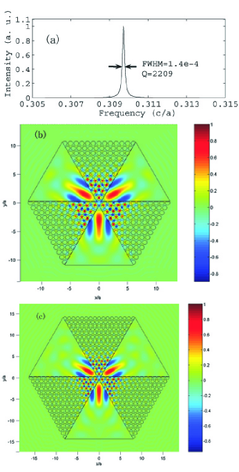
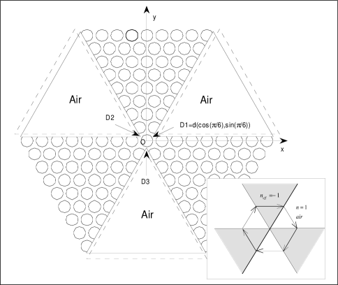
Figure 1 shows the novel design of our open cavity based on the same photonic crystal of negative refraction. It consists of three 60-degree wedges of PC of negative refraction with three 60-degree in-between wedges of air. The whole structure is designed in such a way that all the air-PC interfaces are normal to the -M direction (to reduce the reflection at the air-PC interfaces). The simple ray-trace sketch for a close optical path in the inset of Fig. 1 shows how such an open cavity may work (if the reflection at the interfaces is small).
Besides the direction of the surface termination, the position of the surface termination also has a significant influence on the refraction at an air-PC interface Xiao et al. (2004). In our design, the position of the surface termination can be determined by the location of the tip points , and (see Fig. 1). Due to the symmetry, the coordinates of these tip points can be determined uniquely by a single parameter (the distance between the center O and any of the tip points), i.e. , . In Fig. 1, the dashed lines indicate the position of surface termination for another value of (i.e., when the air wedges move a bit outward).
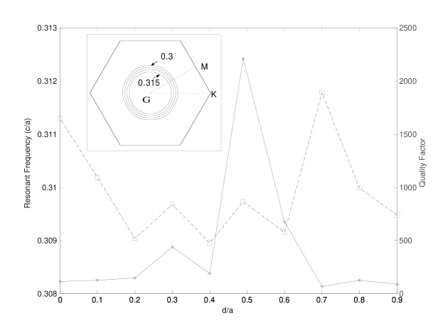
Finite difference time domain (FDTD) method Taflove (2000) is used here to calculate the resonant mode and analyze the resonant property of the present open cavity. The fast Fourier transform (FFT)/Padé approximation Dey and Mittra (1998) is also applied to compute efficiently the resonant frequency and the quality factor , where is the full width half maximum (FWHM) of the spectral response of the cavity Dey and Mittra (1998). We first study how the position of the surface termination influences the quality factor of an open cavity with 13 rows of air holes in each PC wedge. Figure 2 shows how the resonant frequency (squares connected with dashed lines) and the quality factor (stars connected with solid lines) of the open cavity vary with the distance between the origin O and the tip of an air wedge. corresponds to a tangential cut of the boundary air holes (i.e., they just remain whole). When increases from 0 to , the resonant frequency varies in a range of , in which EFS is quite circular (see Fig. 2). This also indicates that the resonance can occur only in a frequency range where an effective negative reflection index can be deduced and is close to .
From Fig. 2 (for the case when each wedge has 13 rows of air holes) one sees that the quality factor reaches a peak value of about 2209 at . The spectral response of the open cavity is plotted in Fig. 3(a) (calculated with FDTD by illuminating the cavity with a pulse and monitoring the evolution of the field; the FFT/Padé method is applied to determine the resonant frequency). From this figure one sees that the resonant frequency is and the FWHM of the spectral response is . Thus, the corresponding quality factor is . Once the resonant frequency is known, we can determine the corresponding modal field by simulating a second propagation and extracting the field pattern at that frequency. Fig. 3(b) shows the corresponding resonant modal field. The present cavity has a symmetry of point group . From Fig. 3(b) one can see that the irreducible representation of the localized modes in the open cavity is for point group Sakoda (2001). The modal field is localized both in the photonic crystal and air. The modal field distribution has a maximal amplitude in air. From Fig. 3(b) one can also see obvious negative refraction at each PC/air interface.
The resonant frequency varies little (within ) as increases. This is understandable since the modal field of the open cavity is localized near the center and consequently the resonant frequency of the open cavity is determined mainly by the distribution of the effective refractive index along a closed optical path near the center. One can easily see that the modal field distribution in Fig. 3(c) (with 17 rows of air holes in each PC wedge) is indeed similar to that in Fig. 3(b) (with 13 rows of air holes in each PC wedge). The quality factor increases a bit from 2209 to 2540.
In summary, we have studied a novel open cavity formed by a photonic crystal with negative effective refraction index. Due to the negative refraction (and the high transmission) at the PC/air interfaces, the propagating wave in the air wedges is connected to that in the PC wedges and thus form a closed path (with zero optical path due to the negative value of the effective refractive index of the PC) for resonance. The quality factor of the open cavity can be higher than . The influence of the interface termination on the resonant frequency and the quality factor has been addressed. The present design idea for an open cavity can be generalized to other PCs of negative refraction (of type (i)).
Acknowledgements.
This work was supported by the National Basic Research Program (973) of China (2004CB719800) and the National Natural Science Foundation of China (under key project No. 90101024 and project No. 60378037).S. L. He’s email address is: sailing@ieee.orgReferences
- Veselago (1968) V. G. Veselago, Sov. Phys. Usp. 10, 509 (1968).
- Shelby et al. (2001) R. A. Shelby, D. R. Smith, and S. Schultz, Science 292, 77 (2001).
- Pendry (2000) J. B. Pendry, Phys. Rev. Lett. 85, 3966 (2000).
- Smith et al. (2004) D. R. Smith, J. B. Pendry, and M. C. K. Wiltshire, Science 305, 788 (2004).
- Chen et al. (2004) L. Chen, S. He, and L. Shen, Phys. Rev. Lett. 92, 107404 (2004).
- Notomi (2000) M. Notomi, Phys. Rev. B 62, 10696 (2000).
- Cubukcu et al. (2003a) E. Cubukcu, K. Aydin, E. Ozbay, S. Foteinopoulou, and C. M. Soukoulis, Phys. Rev. Lett. 91, 207401 (2003a).
- Cubukcu et al. (2003b) E. Cubukcu, K. Aydin, E. Ozbay, S. Foteinopoulou, and S. C. M., Nature 423, 604 (2003b).
- Parimi et al. (2003) P. V. Parimi, W. T. Lu, P. Vodo, and S. Shridar, Nature 426, 404 (2003).
- Berrier et al. (2004) A. Berrier, M. Mulot, M. Swillo, M. Qiu, L. Thylén, A. Talneau, and S. Anand, Phys. Rev. Lett. 93, 073902 (2004).
- Foteinopoulou and Soukoulis (2003) S. Foteinopoulou and C. M. Soukoulis, Phys. Rev. B 67, 235107 (2003).
- Luo et al. (2002a) C. Luo, S. G. Johnson, and J. D. Joannopoulos, Appl. Phys. Lett. 81, 2352 (2002a).
- Ao and He (2004) X. Y. Ao and S. L. He, Opt. Lett. 29, 2542 (2004).
- Zhang (2004a) X. D. Zhang, Phys. Rev. B, 70, 195110 (2004a).
- Luo et al. (2002b) C. Luo, S. G. Johnson, J. D. Joannopoulos, and J. B. Pendry, Phys. Rev. B 65, 211104 (2002b).
- Hu and Chan (2004) X. H. Hu and C. T. Chan, Appl. Phys. Lett. 85, 1520 (2004).
- Zhang (2004b) X. D. Zhang, Phys. Rev. B, 70, 205102 (2004b).
- Ruan et al. (2005) Z. C. Ruan, M. Qiu, S. S. Xiao, S. L. He, and L. Thylén, Phys. Rev. B 71, 045111 (2005).
- Xiao et al. (2004) S. S. Xiao, M. Qiu, Z. C. Ruan, and S. L. He, Appl. Phys. Lett. 85, 4269 (2004).
- Taflove (2000) A. Taflove, Computational Electrodynamics: The Finite-Difference Time-Domain Method (Artech House INC, Norwood, 2000), 2nd ed.
- Dey and Mittra (1998) S. Dey and R. Mittra, IEEE MICR. AND GUIDED WAVE LETT. 8, 415 (1998).
- Sakoda (2001) K. Sakoda, Optical Properties of Photonic Crystals, Springer Series in Optical Sciences 80 (Springer Verlag, 2001), 1st ed.