Images in Christmas Balls
Abstract
We describe light-reflection properties of spherically curved mirrors, like balls in the Christmas tree. In particular, we study the position of the image which is formed somewhere beyond the surface of a spherical mirror, when an eye observes the image of a pointlike light source. The considered problem, originally posed by Abu Ali Hasan Ibn al-Haitham — alias Alhazen — more than a millennium ago, turned out to have the now well known analytic solution of a biquadratic equation, being still of great relevance, e.g. for the aberration-free construction of telescopes. We do not attempt to perform an exhaustive survey of the rich historical and engineering literature on the subject, but develop a simple pedagogical approach to the issue, which we believe to be of continuing interest in view of its maltreating in many high-school textbooks.
1 Introduction
The basic property of geometrical optics for reflection is the equality of the angles of incidence and reflection, given by the equation
| (1) |
Here, we will demonstrate that equality (1) is not respected when analyzing curved mirrors, in particular spherical mirrors, in the educational programs for high-school and university students [1].
One of the corner stones of geometrical optics at the high-shool level is the concept of ideal lens, which reduces the lens to an optical plane, principal and auxiliary axes, and a focal plane with principal and auxiliary foci. The rules for image formation are clear: incident light rays parallel to an auxiliary axis are refracted in the lens such that the refracted light ray passes through the corresponding auxiliary focus in the case of a positive ideal lens, or seem to originate from the corresponding auxiliary focus for a negative ideal lens. No further rules are needed to construct images for any ideal lens or set of ideal lenses. This concept is not only useful, as it approximates well real lenses applied in optical instruments, but also a practical application of Euclidean geometry.
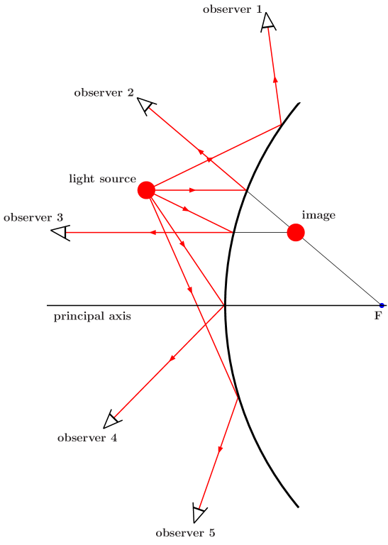
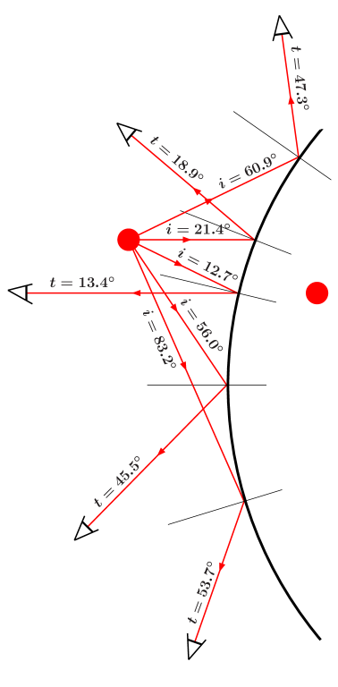
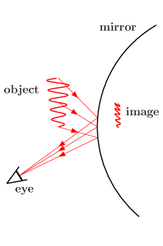
However, ideal lenses should not be confused with ideal spherical mirrors. The ideal spherical mirror is a mirror in the form of a perfect sphere. No simple rules can be applied to construct its images. Nevertheless, almost all physics courses for high-school and undergraduate students contain figures similar to the one represented in Fig. 1a, in order to demonstrate image formation in convex (or concave) spherical mirrors.
|
|
| (a) | (b) |
In Fig. 1b we show the results of measuring the incident and reflection angles at each of the vertices, applying simple Euclidean geometry. Being rather obvious for observer 5, we actually find that none of the vertices respects relation (1). We must therefore conclude that Fig. 1a cannot be correct.
The latter conclusion is no surprise, of course. Since a perfect spherical mirror is spherically symmetric, any choice of principal axis is as good (or bad) as any other. Descartes’ formula for the position of an image does not imply the existence of a focus. It just provides a simple method to determine the place of the image for an observer positioned right behind the light source with respect to the centre of the sphere. For observers which are just a very small angle away from that direction, it constitutes a reasonable approximation. The method given by Descartes can thus perfectly well be applied to optical instruments, where long tubes guarantee that the angles involved are small. However, for the images observed in Christmas balls, it is not a correct method to be applied.
In the following paragraphs, we shall show a simple method of how to determine the images seen by each of the observers in Fig. 1. We are well aware that similar demonstrations must have been presented long ago. But unfortunately, we have not found any references to such work (see also Ref [2]). Since, moreover, it seems to have been completely forgotten, we judged it useful to present our material to a wider public than just our students.
2 Reflection.
Let us consider a pointlike light source and a spherical mirror. We assume that the eye lens is small enough to be considered pointlike as well. The relevant light rays must all be in the plane determined by the centre of the sphere, the position of the light source, and the eye. Consequently, we may study the subject in two dimensions.
We take the centre of the circle, which has radius , at the origin of the coordinate system. In Fig. 2 we show a light ray emitted by a light source located at , and reflected by the spherically curved mirror at the vertex .
Since we are essentially left with a two-dimensional problem, we may perform the geometrical calculations by using complex numbers. Thus, let us define the complex numbers (object location) and (vertex location), i.e.,
| (2) |
The vector points from the vertex to the light source (object) along the incident light ray. Furthermore, the angle (see Fig. 2) is defined as the angle between and . Consequently,
| (3) |
When by using Eq. (3) we rotate the vector over an angle , i.e.,
| (4) |
then we obtain a vector in the direction of the reflected light ray. Using now Eq. (4), we deduce the following expression for the straight line which coincides with the reflected light ray ( real):
| (5) |
3 The image
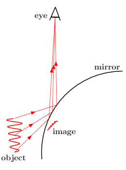
The small bundle of light rays which strikes the eye lens has a very small area of convergence, as can be understood from Fig. 3.
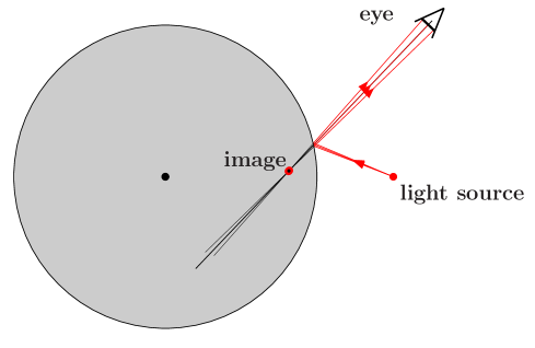
This small area is where the eye supposes the light rays are stemming from, hence the image of the light source.
By varying the angle in Fig. 2, we obtain different trajectories for light rays originating from the same light source at . We are here interested in the intersection of the straight lines that coincide with the reflected rays of two different suchlike trajectories. We indicate their vertices by and , respectively. We define the image of the light source, for observers in the direction characterised by , as the point of intersection of the two trajectories, in the limit of vanishing . In the Appendix it is shown how one obtains thus, the position of the image of the light source. From Eq. (37) one easily deduces the expression
| (6) |
The denominator in this fraction is real. Consequently, it is an easy task to extract the and components of the image position. One gets
| (7) | |||||
In Fig. 3 we show some pictures. We indicate the positions of the light source, the eye, and the centre of the spherical mirror. Three different light rays are reflected on the surface of the sphere and then reach the eye.
& We assume the location of the image to lie where these rays intersect one another. A small red dot labelled by indicates the position of the image for the central direction, which follows from Eq. (7). The image in the upper-left picture of Fig. 3 can approximately be reconstructed from Descartes’ formula. But, the other three images come obviously at different locations.
The reason that we see a “sharp” image of the pointlike light source is due to the smallness of our eye lens. More accurately, it stems from the ratio of the diameter of the pupil of the eye and the curvature radius of the spherical mirror. Hence, perfectly sharp images are only to be expected for an infinite radius of curvature, which just represents a flat mirror. Nevertheless, for large spherical mirrors, the resolution of the virtual image observed by the eye is good enough to be considered sharp. However, its location depends on the position of the eye.
For a light source on the axis () and for , we obtain for the image location
| (8) |
Moreover, one then finds
| (9) |
which is Descartes’ formula for spherical mirrors.
4 The angle
The question is how to determine the angle in the case that the positions of the light source and the eye are given.
Let us define the complex number for the coordinates of the eye lens, i.e.,
| (10) |
From Fig. 2, and in analogy with Eq. (3), we obtain
| (11) |
Combining Eqs. (3) and (11) gives
| (12) |
or
| (13) |
The right-hand side of Eq. (13) is real, whence for the imaginary part of the left-hand side we conclude
| (14) |
which is equivalent to the fourth-order equation
| (15) |
4.1 The solutions to Eq. (15)
The biquadratic Eq. (15) is in the literature known as the Billiard Problem of al-Hasan, named after the Arab scientist Abu Ali al-Hasan ibn al-Haytham (965–1040 A.D.) [3, 4]. It corresponds to the following problem, which had already been formulated in 150 A.D. by the Greek scientist Ptolemy: “Find, for arbitrary initial positions of the red ball and the white ball, the point on the edge of a circular billiard table at which the white ball must be aimed in order to carom once off the edge and collide head-on with the red ball”.
From the definitions of , , , and the subsequent definition of in Eq. (2), it may be clear that reflection in the interior of the circle representing the cross section of the spherical mirror can be studied in exactly the same way as reflection in the exterior, by considering instead of , and instead of , which leads to exactly the same Eq. (15).
In general, there are four solutions , , , and to the equation
| (16) |
However, when , the solution to Eq. (16) is not a physical solution to Eq. (15). Although we have not studied the situation exhaustively, we find that generally there are two solutions to Eq. (15), but sometimes there are four (see also Ref. [5]), depending on the complex parameters and .
& \begin{picture}(220.0,220.0)(-110.0,-110.0)\end{picture}
The different cases, corresponding to , , , , , and , must be studied separately. In Fig. 3 we show two examples for a circular billiard.
5 Deformation
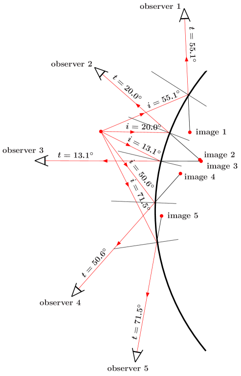
Now that we have solved the problem of finding the vertex on the curved mirror where the light ray passing from the object to the eye is reflected, we may construct the images for the situation shown in Fig. 1. The result is depicted in Fig. 6.
|
Furthermore, we may now construct the images of extended objects, and study their deformation. In Fig. 7, we give a few simple examples.
|
|

|
|
6 Conclusions
The complete resolution of the Billiard Problem (15), posed by al-Hasan in the context of what nowadays is called geometric optics, had to wait for many centuries. First it was necessary to derive an analytic form for the solutions to biquadratic equations like Eq. (16). Apparently found by Ferrari, it was published for the first time in Cardano’s “Ars Magna” in 1545. The first one to subsequently solve the Billiard Problem of al-Hasan was Christiaan Huyghens.
The problem would probably have ended up in the history books, since “once solved, forever solved”. However, for optical equipment, where the angles of reflection are small, Descartes formulated an approximation, amounting to basically linear equations. Anything that has larger reflection angles is considered an aberration in his philosophy. Ever since, a whole generation of physicists emerged completely unaware of al-Hasan’s Billiard Problem, who systematically applied Descartes’ approximation also to large angles , thus arriving at totally wrong conclusions. Therefore, we should rub up al-Hasan’s Billiard Problem, and reintroduce it in our optics courses, so that new generations can fully enjoy the perfectly sharp images in Christmas balls, without feeling uneasy for having been told that such wonderful images should be considered aberrations.
For undergraduate students the full subject can be treated, involving some simple computer programming. One can either choose a point on the spherical mirror, and construct the image by the use of formulae (7) and from the direction of the reflected light ray, or one can select the position of the eye pupil, and determine the vertex by means of Eq. (15). However, for youngsters at high schools, we recommend to only deal with it qualitatively, using examples like Figs. 3 and 6.
Acknowledgments
We are grateful for many useful discussions with our colleagues, in particular with Alex Blin, Brigitte Hiller, João da Providência Santarém e Costa, Francisco Gil and Constança da Providência, as well as with João Paulo Fonseca from the Escola Secundária de Tondela.
References
- [1] for example: The Physics Classroom and Mathsoft Engineering and Education, Inc. The Physics Classroom, a high school physics tutorial, 2004 http://www.physicsclassroom.com, Lesson 4: Convex Mirrors. D. Halliday, R. Resnick and J. Walker, Fundamentals of Physics, 6th edition (2001), edt. John Wiley and Sons, Inc. V. P. Coletta, College Physics, (1995), edt. WCB/McGraw-Hill. W. E. Gettys, F. J. Keller and M. J. Skove, Physics, (1989), edt. McGraw-Hill, Inc. F. J. Bueche and D. A. Jerde, Principles of Physics, (1995), edt. WCB/McGraw-Hill. R. A. Serway, R. J. Beichner and J. W. Jewett, Physics for Scientists and Engineers with Modern Physics, 5th edition (2000), edt. Saunders College Publishing.
- [2] M. V. Berry, Physics Education 7 (1972) 1–6.
- [3] http://mathworld.wolfram.com/AlhazensBilliardProblem.html
- [4] G. E. Fishter, “On Reflexion at a Spherical Mirror”, J. Sci. Instrum. 24 (1947) 97–98.
- [5] M. Drexler and M. J. Gander, SIAM review Vol. 40, No. 2, (1998) 315-323.
Appendix A The point of convergence for adjacent reflected light rays
We consider here two reflected light rays, characterised by two different vertices and . In accordance with formula (5), we may represent the two straight lines coinciding with the two reflected rays by (, real)
| (17) |
The intersection of the two trajectories follows from
| (18) |
which, since and are real, actually corresponds to two equations, one for the real part and one for the imaginary part, namely
| (19) |
The system of equations (19) can be solved for and .
In order to avoid lengthy formulas, we define
| (20) |
Using definitions (20) and formula (17), we obtain
| (21) |
Inserting the result (21) into the two relations (19) gives the two equations
| (22) |
which can be cast in matrix form and are readily solved by
| (29) | |||||
| (32) |
Next, we take and expand the various terms of Eq. (32) to first order in and . In the limit , one has moreover
| (33) |
This can most easily be understood, when one, using Eq. (2), defines
hence, to lowest order in , one finds . Consequently, since , and are real,
Using, moreover, the definitions (20), we determine, in the limit ,
and similarly,
| (34) |
| (35) |
On substitution of the results (34) and (35) into expressions (32), we obtain for the parameter at the point of intersection, in the limit of vanishing , the result
| (36) |
Finally, using Eq. (36), we determine the point of intersection, , of the two straight lines (17) in the limit of vanishing .
| (37) |
The variable indicates how deep the “image” is below the surface of the spherical mirror, measured from the mirror surface, along the direction of reflection, to the point where the small bundle of reflected rays seems to emerge. Alternatively, for practical purposes, one could determine this “depth” from
One measures with a ruler, the lengths of and , the latter equals half the distance from the vertex to the other intersection of the mirror and the line which coincides with the reflected light ray, and performs the above calculation. For small angles , one obtains the image location of Descartes, whereas, for larger angles the location of the image is different. For , one obtains zero depth.