100 ps time-of-flight resolution
of Dielectric Resistive Plate Chamber
Abstract
Time of flight of a minimum ionizing particle along a fixed base has been measured with a 100 ps accuracy by means of a Dielectric Resistive Plate Chamber (DRPC) with mm gas gaps. DRPC timing characteristics have been studied with different applied voltages, discriminating thresholds and beam intensities. It may be stated that the time-of-flight resolution of gaseous detectors developed within the ALICE experiment has reached the level of the best known scintillation counters.
1Institute for Theoretical and Experimental Physics (ITEP),
B. Cheremushkinskaya 25, Moscow, 117218, Russia.
2Center of Perspective Technologies and Apparatus (CPTA),
Preobrazhenskaya pl. 6/8, Moscow, 107076, Russia.
During the last several years a revolutionary progress in breakdown suppression inside gaseous time-of-flight detectors was achieved by introducing, in different ways, a resistivity inside the gas gap [1, 2, 3]. Despite of this fact, there was a poor idea about timing properties, which may be principally manifested by these detectors.
A value of 100 ps seems to be a natural limit in this sence. Basing on the ALICE physical conditions, 100 ps time-of-flight resolution is sufficient for /K/p separation in a real momenta range. Untill recently, such fine resolution could be provided only by modern scintillation counters and Pestov spark counters [4]. As an example, the timing system based on scintillators and photomultipliers, proposed for the STAR project at RHIC, provides the time resolution of about 90 ps [5].
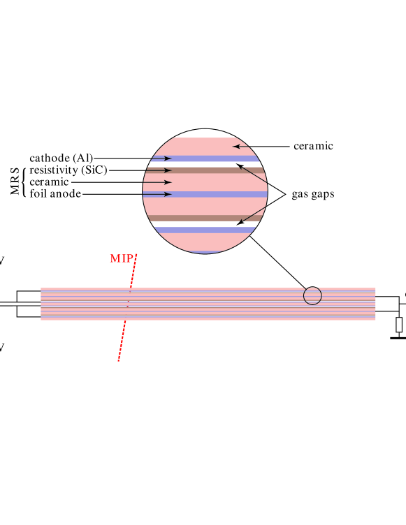
The detector, described in the given paper, is schematically presented in Fig. 1. Dielectric Resistive Plate Chamber (DRPC) consists of several ceramic plates (0.5 mm of ordinary unpolished ceramics) which form four gas gaps, each 0.3 mm wide. In accordance with the expectations, decreasing the gap width has led to the rise of the time resolution. The number of gaps (two in previous version [2]) was doubled to keep the MIP registration efficiency close to 100%.
The chamber consists of two types of electrodes. Ceramic cathodes are metallized with aluminum. Dielectric-resistive electrodes are also made of ceramics metallized with aluminum on the one side and covered, through evaporation, with semi-conducting SiC on the other side. The plates are assembled in pairs so that the metal layer, common for two gaps, is positioned inside, and the semi-conducting layers are turned towards the gaps. The idea of electrical connection between the semi-conductor and the metal is described in Ref. [2]. The detector has a square working surface of cm2.
Methods employed in the measurements of TOF resolution and registration efficiency at ITEP and CERN accelerators was, in general, similar to that decribed in Ref. [2]. The same front-end electronics and gas mixture consisting of 85%C2H2F4 + 5%isobutane + 10%SF6 were used. The start part of the setup, based on scintillation counters, was modified, so that the information from several detectors could be analized simultaneously.
The counting rate, or efficiently registered particle flux over the working surface, is an important parameter of DRPC. During the measurements the rate was fixed at the level of 1 kHzscm-2, which is higher than that predicted under the ALICE conditions (100–200 Hzscm-2). Special measurements of the way the time resolution dependends on the rate were performed as well.
| (a) | (b) |
|---|---|
 |
 |
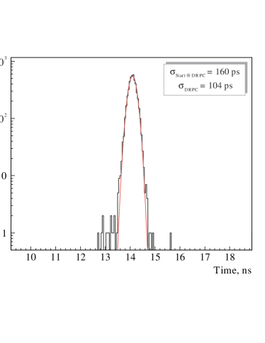
A typical time-of-flight distribution, summarised over the whole range of amplitudes, with the total registration efficincy close to 95%, is shown in Fig. 2a. One can see that the standard deviation is really on the level of 100 ps, and the distribution has unsignificant tails. Fig. 2b represents the same data in more detail: the time resolution is shown for different amplitudes. The dependence is very slight, the resolution stays close to 100 ps in the whole range of amplitudes, which explains the absence of tails in Fig. 2a.
| (a) | (b) |
|---|---|
 |
 |
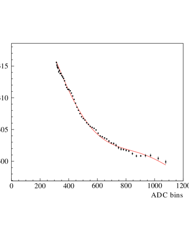
Actually, the timing resolution is calculated after slewing correction, which takes into account the fact that signals with larger amplitudes are triggered by the constant-threshold discriminator at earlier times. Such a correction influences the timing distribution in a strong way. It is normally performed with a polynomial function in a way shown in Fig. 3a.
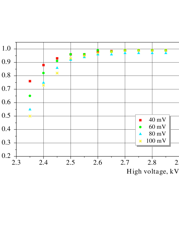
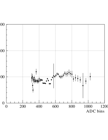
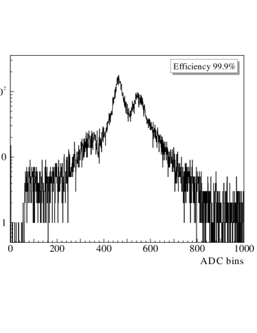
The amplutude spectrum obtained from the amplifier output is shown in Fig. 3b. More specifically, it shows the charge integrated by a charge-sencitive ADC. Although the front-end electronics is not linear in the whole range of amplitudes, it may be seen that the amplitude spectrum has a peak, staying far from the pedestal bounder on a slightly changing background. Amplitude magnitudes correspond to the gas amplification of 107 and allow to obtain excellent registration efficiency at different high voltages and electronics thresholds. The dependence of efficiency on the high voltage is shown in Fig. 4 for different electronics thresholds. Even at the threshold of 100 mV there is a clear plateau, in which the efficiency stays close to 100%.
| (a) | (b) |
|---|---|
 |
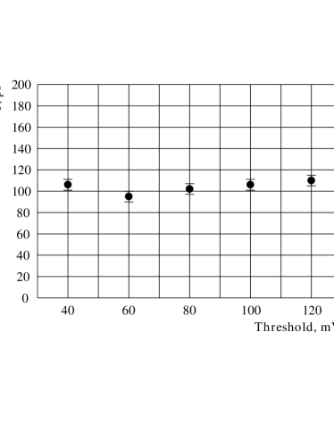 |
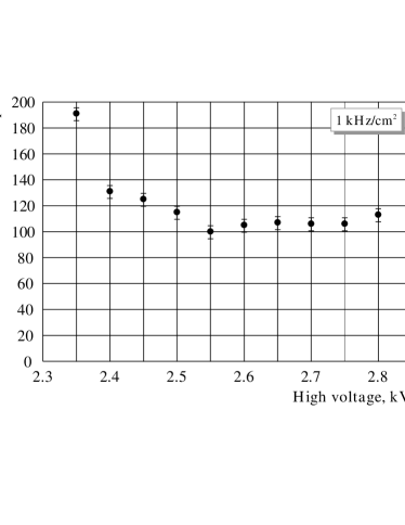
The fact that the TOF resolution does not depend on the high voltage and the discriminating threshold, is illustrated in Fig. 5.
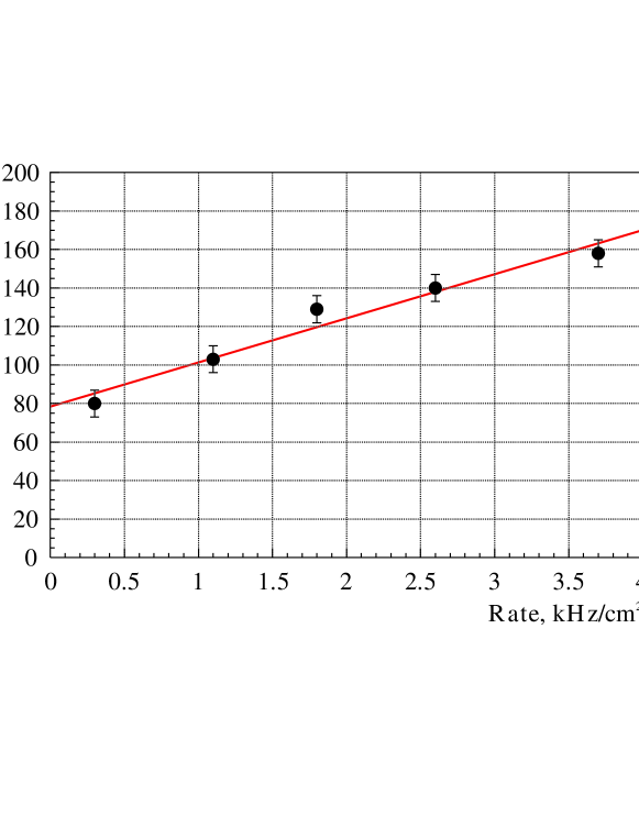
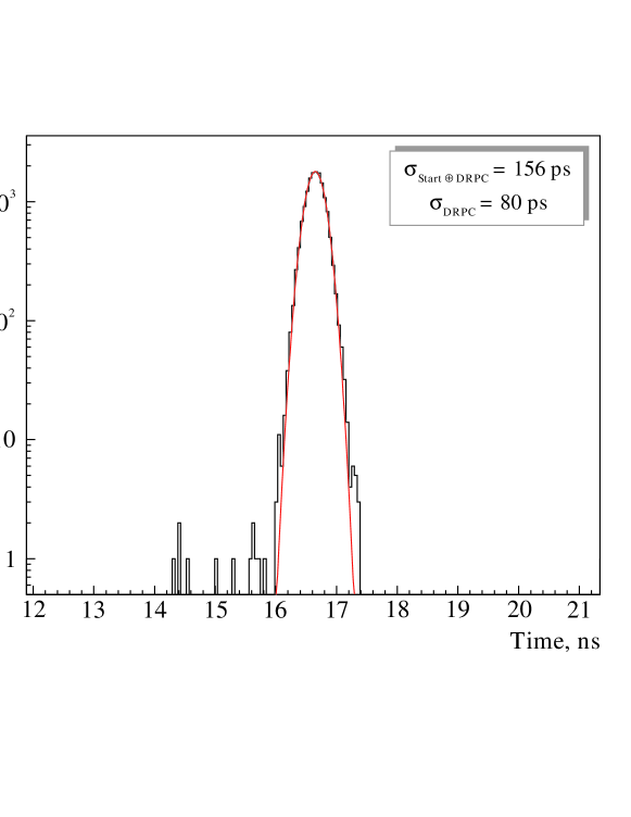
All the results described above were obtained at a fixed counting rate. A special experiment was performed to study the rate influence on the detector properties. Fig. 6 shows the dependence of the TOF resolution on the particle flux at 40 mV electronics threshold. The resolution increases with the rate up to approximately 150 ps. But under the ALICE conditions (the very beginning of the scale) it may be expected to be as low as 80 ps. Fig. 7 shows the low rate resolution in detail. The distribution is still very clear with the tails admixture being less than 10-3.
The study of DRPC timing properties was performed with a support from RFFI grant #99–02–18377.
References
- [1] V. Golovin, A. Smirnitsky, Patent for invention of Russia #2148283, 13.11.1998.
- [2] A. Akindinov, V. Golovin, A. Martemiyanov, et al., Preprint ITEP 45–98, arXiv:physics/0410103.
- [3] P. Fonte, A. Smirnitski, M. C. S. Williams, Nucl. Instrum. and Meth. A 443 (2000) 201.
- [4] H. R. Schmidt, Nucl. Phys. B (Proc. Suppl.) 78 (1999) 372.
- [5] W. J. Llope, F. Geurts, J. W. Mitchell, et al. Nucl. Instrum. and. Meth. A 522 (2004) 252.