A novel String Banana Template Method for Tracks Reconstruction in High Multiplicity Events with significant Multiple Scattering and its Firmware Implementation
Abstract
Novel String Banana Template Method (SBTM) for track reconstruction in difficult conditions is proposed and implemented for off-line analysis of relativistic heavy ion collision events. The main idea of the method is in use of features of ensembles of tracks selected by 3-fold coincidence. Two steps model of track is used: the first one – averaged over selected ensemble and the second – per event dependent. It takes into account Multiple Scattering (MS) for this particular track.
SBTM relies on use of stored templates generated by precise Monte Carlo simulation, so it’s more time efficient for the case of 2D spectrometer. All data required for track reconstruction in such difficult conditions could be prepared in convenient format for fast use. Its template based nature and the fact that the SBTM track model is actually very close to the hits implies that it can be implemented in a firmware processor. In this report a block diagram of firmware based pre-processor for track reconstruction in CMS-like Si tracker is proposed.
1 Introduction
Some modern experiments have to deal with tracks in high multiplicity events in spectrometers with finite granularity detector and often in a non-uniform magnetic field and in the presence of significant MS. Considerable MS up to ten mrad per silicon detector plane, energy loss at low momenta and issues like clusterization and large incident angles potentially create difficulties in pattern recognition and track fitting in high multiplicity events even for primary tracks.
1.1 Effect of Multiple Scattering
Usually for pattern recognition local methods are used and fitting of track’s parameters in the case of non negligible MS is accomplished by a modification of linear Least Square Method (LSM). In any case Covariance matrices of different sizes should be prepared and inverted during fitting procedure. Iterative procedures are required in the non-linear cases. Long combinatorial loops inevitable for local pattern recognition methods require much computation time at the fitting stage.
In the SBTM there is another approach to handle effect of MS. There are no matrices and fitting procedure is quite different from standard – the best track parameters are achieved for the geometrical model most close to trajectory hits. There are few more parameters for SBTM track model and they depend on particular set of multiple scatterings for a given track. They provide additional (per event) corrections for track parameters.
Capabilities of the SBTM are demonstrated by comparison of track parameters resolutions to results received by LSM method for toy model spectrometer. Proposed global method has good pattern recognition features for primary tracks in high multiplicity events because of narrow search windows and a priori known momentum. Some basic characteristics of implemented into C++ SBTM track reconstruction software for environment of heavy ion collisions are provided.
2 Features of SBTM
The main idea of the method is in use of ensembles of particle trajectories with three fixed points for templates accumulation [1]. Two steps model of track is used: the first one – averaged over ensemble (although different from “standard”) and the second – per event dependent (takes into account MS for this particular track).
Ensembles of tracks from given vertex point which pass through particular pixels (strips) {i,j} in two Reference Planes (RPs) are formed. For such ensemble (which geometrical image has a -like shape in magnetic field, see Fig. 1) all necessary values corresponding to each internal planes (as centre of s, their widths, angles, lengths an so on) could be saved.
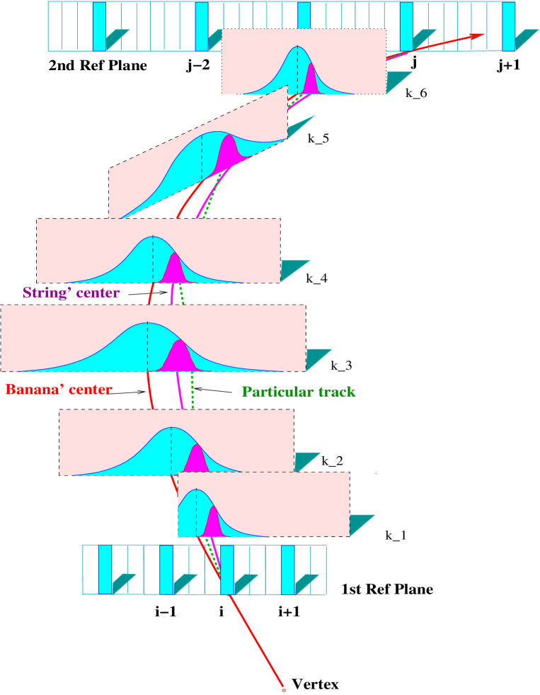
At first track recognition stage one check different combinations of {i,j} signals in RPs and select such which has proper number of signals in all (or in almost all planes) inside of window. At the second stage relative positions of signals inside are checked and if they are inside a more narrow window () track candidate is recognized. Pattern recognition is accomplished in two relatively simple stages and there is no traditional fitting procedure for obtaining of track parameters (no hard computations). Because of such conditional correlation on MS the actual width of template’s search window () on the 1-st stage of pattern recognition becomes relatively small. On the second stage the search window () is “shrunk” again few times (about 4…6). This simplifies and accelerates (the global in nature) pattern recognition process, by avoiding large combinatorial trees search.
SBTM relies on use of stored templates, generated by precise Monte Carlo simulation prepared in advance. All necessary data required for track reconstruction could be prepared for fast use. SBTM track model is actually very close to trajectory hits (even for low momentum tracks), so it can be implemented in a firmware processor. For high multiplicity events without external track seeds number of combinations {i,j} to be checked becomes large, so hardware or firmware processor which could accomplish this task often in parallel and much faster could be used as a trigger processor or pre-processor for subsequent off-line analysis on standard computers (providing selected tracks candidates for final qualitative checking).
2.1 Comparison to LSM results
For the purpose of demonstration, the SBTM method was applied to a two dimensional toy model spectrometer as used in [2]. It consists of four high resolution silicon detectors uniformly distributed over 12 cm track length followed by thirteen gas detectors again at equal spacing over 120 cm track length. All planes are parallel. Properties of this setup are summarized in Table 1 of [2]. The spectrometer is placed in a 1T transverse magnetic field. The thickness of Si planes is 0.4 % of radiation length, for gas detectors it’s 0.1 %. The spatial resolutions are 5 and 200 respectively.

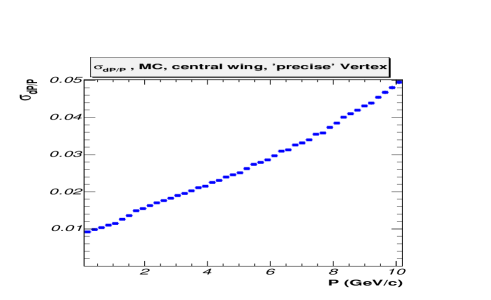
The optimal track fitting (OTF) used in [2] reproduces the results of the global fit [3]. On Fig. 2a) momentum resolutions for SBTM and OTF methods are shown. SBTM could be used for vertex finding also. Pattern recognition including vertex finding was done initially for few vertex points along Y axis to find the proper vertex. To achieve good resolution, fine track tuning-rotation of template’s ends inside strip width for FRP (layer 4) and inside of for SRP (last layer) was performed. In that case two additional parameters were used for two s (one before FRP and the second - between FRP and SRP). SBTM potentially provides better track parameter’s resolutions than method equivalent to LSM. Fig. 2b) shows how close track model is from actual hits; it is received for the ideal case when each plane has very good space resolution (less than few m).
2.2 Implementation for PHOBOS spectrometer
The PHOBOS Spectrometer [4] (for relativistic heavy ion experiment at RHIC) has two arms (see Fig. 3) with Si detectors, located on the opposite sides of the beam pipe. The first few nearest to the pipe planes of each Spectrometer arm reside in low magnetic field region, while the subsequent planes are placed in a vertical field with maximum of 2 T. The dimensions of the silicon sensor pads range from 0.4 mm to 1.0 mm in the bend direction. Additional segmentation in the vertical direction is provided: first four layers (closest to the interaction region) have 1 mm height pads; for the rest layers heights progressively increase from 6 to 19 mm. Initial objective of tracking was low transverse momentum charged particles.

Templates are generated for different vertexes with step 5 mm along Z axis (along beam pipe). Ensembles of tracks with common vertex which pass through a particular pair of pixels {i,j} in two Reference Planes (RPs) are used for calculation of mean values and some s for different templates parameters. In our case the last plane before magnet and one of the last plane in magnet are used as RPs.
SBTM has high efficiency in the high multiplicity Monte Carlo events () for track reconstruction in the wide range of momenta, starting from the lowest possible values for tracks which cross all planes (80 MeV/c for , see Fig. 4).
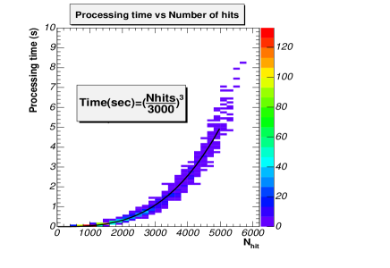
This pattern recognition method and use of dE/dx information for each channel permit to reconstruct close tracks which share up to of their hits. For real data occupancies reach the level of 25 % in high regions of spectrometer. On Fig. 5 processing time (which includes pattern recognition and ghost cleaning) is shown as a function of number of the hits in the arms for real data in (Au + Au) collisions at GeV.
3 Firmware Realization
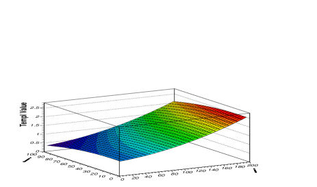
Templates volume could be large if data are saved for each possible combination of {i,j} reference channels. But due to the fact that these 3D surfaces are quite smooth (as on Fig. 6) they could be parametrized as 2D functions (or slices of 2D histogram) and in that case the size of templates could be relatively small. Another option is to save template values for the grid points as on Fig. 6 and then use linear interpolation for internal points. In that case the fast look-up tables with required address space become affordable.
In this paper a block diagrams of firmware based pre-processor which uses grid templates with relatively fast interpolation (using 8 bit multiplication look-up tables) is presented and basic features of implementation are described. It consists of a master module BMM (Fig. 7) and of number of processing modules BPMs (one per layer or part of the layer; Fig. 8) connected by fast custom bus. During initialization process BPMs receive corresponding plane’s templates data in convenient format. All local coordinates and widths are converted into fixed float format with small bins.
At reconstruction stage the input data from spectrometer events are transmitted in parallel in raw format by dedicated computer nodes. In the processor’s modules this information is converted into reference channel numbers {i,j} (BMM) and fixed float format (BPMs). Detector planes are subdivided into small sub-frames (as Si wafers for example) which have their relative numbering. Event data buffers for processing are saved in FIFOs. If there is fast Vertex processor then its information could be received by BMM, otherwise Tracking Processor should check different vertex positions to find one with optimum number of tracks and their deflections from the s.
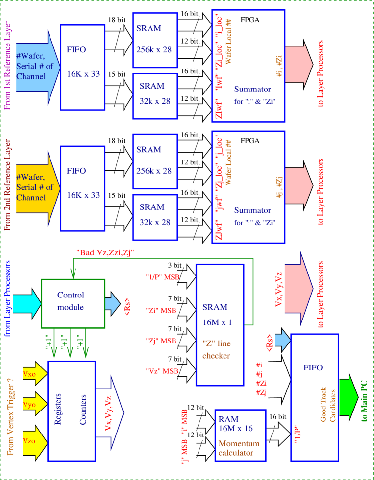
Master module receives information from two reference planes. It loops over all hits in both RPs for all possible combinations of {i,j} in the mode without external designation. BMM has a look-up memory for checking that three points: vertex and two reference pixels {i,j} in two RPs are close to the strait line in the Z plane (along magnet field). It could decrease the number of combinatorial loops in BPMs by factor (for geometry similar to CMS Si tracker).
After preliminary Z selection of the pairs of hits BMM provides {i,j} indexes for template’s grid addresses for processor modules. It asks BMPs to verify the existence of signals inside the windows with indexes {i,j}. If there are enough signals in all planes (conformation signals from all BPMs, or almost all for realistic detection efficiencies) inside that particular , then this {i,j} could be a good candidate in the case of low occupancy event.
At this stage it’s not yet final track candidate. One need to check that signals in all planes inside such could be localized in much more narrow window – with relative deflection ( parameter). Such decision is based on received information about relative deflection of hits from ’s centres in each plane (from all layer processors; in 1D histogram’ position code).
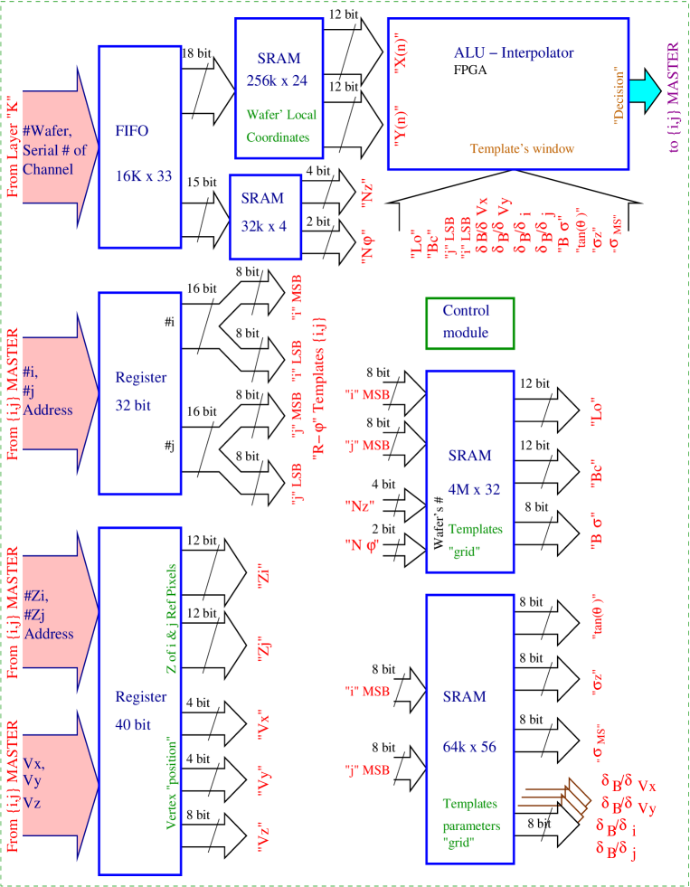
BMM accumulates the histogram of and if there is such combination of signals which gives histogram maximum over some threshold – a new {i,j} track candidate’ information and additional parameter are saved into output buffer. At this stage the momentum value of candidate taken from templates is corrected based on . Such search at the the second stage of patten recognition is accomplished by pipelined firmware architecture of BMM.
For the case of events with 1000 tracks in acceptance of such pre-processor one could expect processing time to be about (50…100) ms if the vertex is provided externally. If external track seed information is available – then master module organizes search of candidates inside limited number of nearest signals in reference planes.
In order to keep processing time reasonably small it’s possible to split data from barrel tracker into few “uncorrelated” segments which have “small” overlapping (because of bending of trajectories at low momenta). It will help essentially because number of combinatorial checks is proportional to the (where N is number of tracks or hits per layer).
Acknowledgments
The authors are grateful to W. Busza for support. This work was partially supported by U.S. DoE grant DE-FC02-94ER40818.
References
-
[1]
P.Kulinich, Proceedings of DPF2004, International Journal of Modern Physics A (IJMP).
arXiv:physics/0502063 - [2] G. Lutz, Nucl. Instr. and Meth. A 273 (1988) 349.
- [3] E.J.Wolin, L.L. Ho, Nucl. Instr. and Meth. A 329 (1993) 493.
- [4] Nucl. Instr. and Meth. A 499 (2003) 603.