Power loss in open cavity diodes and a modified Child Langmuir Law
Abstract
Diodes used in most high power devices are inherently open. It is shown that under such circumstances, there is a loss of electromagnetic radiation leading to a lower critical current as compared to closed diodes. The power loss can be incorporated in the standard Child-Langmuir framework by introducing an effective potential. The modified Child-Langmuir law can be used to predict the maximum power loss for a given plate separation and potential difference as well as the maximum transmitted current for this power loss. The effectiveness of the theory is tested numerically.
pacs:
52.59.Mv, 52.59.Sa, 85.45.-wtoday
I Introduction
The motion of charged particles accelerated across a gap is of considerable interest in fields such as high power diodes and vacuum microelectronics. There are two possible mechanisms that lead to a saturation in the transmitted current. One, where the voltage difference is increased till all the charges that are produced at the cathode, are transmitted. The other, where the voltage is held fixed and the charges produced at the cathode are made to increase (e.g. by increasing the temperature in a thermionic diode or by increasing the power of a laser in case of a photocathode). Interestingly, a saturation is observed even in the second case and the current is said to be space charge limited. A useful approximation for the amount of current flowing in such cases is the Child-Langmuir expression for transmitted current between two infinite parallel plates. For electrodes having a potential difference and separated by a distance , the Child-Langmuir current density is expressed as child ; langmuir ; BB
| (1) |
where is the magnitude of the charge and the rest mass of an electron. In one-dimensional situations (plate dimension much larger than their separation), this is also the current density at which some electrons, instead of moving towards the anode, return to the cathode due to mutual repulsion (space charge effect). This is referred to as critical current density. In the above scenario, the initial velocity of the electrons is zero. Generalizations for non-zero initial velocity can be found in non0 ; akimov ; pop3 .
In two dimensions, analytical and numerical studies lugins ; CL2D ; lau indicate that the critical current is somewhat higher than the Child-Langmuir expression and is given by lugins ; lau
| (2) |
for infinite plates with a finite emission area. Here is the width of the emission strip, is the anode-cathode separation and . For a circular emission area of radius R, the Child-Langmuir law takes the form lau
| (3) |
in the limit .
The picture presented above is considerably simplified as it is based on electrostatic analysis. Nonetheless, it suffices when the diode is closed. In reality, as the current starts flowing, electromagnetic radiation is emitted. In a closed cavity, the emitted radiation opposes the flow of electrons in the region near the cathode while in the region towards the anode, it enhances the acceleration due to the applied field fnote0 . Thus, electrons regain the emitted energy from the electromagnetic field so that the net field energy attains equilibrium.
Most often however, diodes are “open” due to the presence of either a mesh anode (such as in a vircator) or insulating dielectrics in the pulse forming line of the cavity diode or a dielectric window as in a photocathode. This results in a loss of electromagnetic radiation. The electrons are thus unable to reabsorb all the emitted radiation and hence acquire a lower energy on reaching the anode as compared to the case of a closed diode. This also leads to a drop in transmitted current due to the enhanced repulsion between the slowly moving electrons. Thus, diodes open to electromagnetic radiation cannot be governed by any of the above Child-Langmuir laws. Interestingly, there are several instances where deviations from the Child-Langmuir law have been observed chung ; nassisi02 ; nassisi94 . In cases where the current measured is considerably higher, modifications to the Child-Langmuir law take into account the expansion of the plasma formed at the cathode. This leads to a decrease in the anode-cathode separation chung ; nassisi02 with time, . The separation in eq. (1) is thus replaced by where is the plasma expansion rate nassisi02 . Transmitted currents lower than the Child-Langmuir law have also been observed. On completion of this work, we were made aware of such a case in experiments using photocathode. An explanation put forward for this observation takes into account the impedance of the plasma formed at the cathode so that the voltage in eq. (1) is replaced by where is the current ( where is the emitter area) and is the plasma impedance nassisi94 ; nassisi02 . However, comparisons with actual measurements of impedance were not made and the problem may thus be considered open. The form of this modified law (replacing by ) is however general enough to account for any loss mechanism and the one that we propose here due to leakage of electromagnetic radiation can also be expressed in such a form. While we are not aware of direct measurements of power loss in a diode, it is our hope nonetheless that the modification that we propose serves to explain some of the deviations from the standard Child-Langmuir law observed in experimental situations.
We shall first demonstrate in section II that there is indeed a leakage of electromagnetic radiation and a drop in transmitted current in open diodes using a Particle In Cell (PIC) simulation. We shall thereafter show (section III) how the Child-Langmuir can be modified to account for the loss of energy due to the leakage of electromagnetic radiation.
II PIC simulation of Open Diode
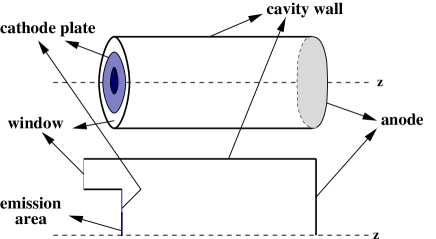
Consider a cavity diode as shown in fig. 1. It consists of a cathode plate with emission from a part of the cathode plate (the dark region in fig. 1), an anode plate and an outer cavity wall. The gap between the cathode plate and the cavity wall is the “open window” through which radiation leaks out. We shall consider here a cathode-anode separation, mm, the radius of the cavity wall cm, the radius of the circular emission strip cm and the applied voltage on the cathode-plate kV (the other parts of the diode are grounded). The radius of cathode plate, varies from 4 cm to 12.5 cm, the last corresponding to a closed diode. For the closed geometry, eq. (1) predicts MA/ while eq. (3) gives MA/. For a beam radius of cm, the corresponding currents are KA and KA respectively.

Our numerical studies have been carried out using the fully electromagnetic particle-in-cell (PIC) code XOOPIC version 2.51 b(c) xoopic and verified using a suitably modified form of the electromagnetic PIC code SPIFFE 2.3 spiffe . The modification in SPIFFE takes into account open boundaries by applying first order Mur type boundary conditions Mur .
The results we present here have been obtained using XOOPIC. In the input file, the cavity wall and anode plate are considered as “conductors” while the cathode plate at the “beam emitter (VarWeightBeamEmitter or FieldEmitter)” is an “equipotential” where the applied voltage is fixed in time. The simulation begins with an evaluation of the static fields by solving the Laplace equation. In order to study more realistic voltage time profiles (figures 10 and 11), we have suitably modified XOOPIC such that the applied fields are evaluated at every time step. Unless otherwise stated, the applied fields will be considered static in this paper.
At the open window, an “exitport” is used to evaluate the power emitted through it. The number of mesh points in azimuthal and radial directions are typically 100 and 250 while the time step s. The number of particles emitted per time step varies between 200 and 700 depending on the current. These calculations have been performed in the absence of any externally applied magnetic field.
For each opening, we increase the injected current till the transmitted current attains (quasi) saturation fnote1 ; pop1 . We then record the transmitted current and the power emitted through the open window. Note that for each simulation, we ensure the onset of steady state behaviour in the transmitted current (see fig. 2) to eliminate the effect of transients.


Fig. 3 shows a plot of the transmitted current density as a function of the opening . There is a monotonic decrease as the window opening increases. In figure 4, we plot the power emitted through the window as a function of the opening . The power peaks at cm or cm.
To understand the relation between the area of the open window and the emitted power, it should first be noted that the emitted power is zero for a closed diode () even though the electromagnetic field energy inside the diode is high. As the opening increases, some of this field energy leaks out. Thus the emitted power increases, the current drops and the field energy inside reduces as the opening is increased. However, at very large openings, most of the emitted radiation leaks out. Consequently, the transmitted current and hence the field energy inside the diode must be small. Thus, even though the window area is large, the power emitted must be small. It follows that at a critical value of the opening, the field energy inside, transmitted current and window area are such that the power emitted is at a maximum as observed in fig. 4.
We thus find that the transmitted current decreases with an increase in window area while the emitted power peaks as the window area is increased from zero and then decreases for larger openings load . An exact theory predicting such a behaviour is rather formidable and shall not be attempted here. However, in the following, we shall argue how the power loss can be incorporated within the Child-Langmuir framework.
III Modified Child-Langmuir Law for open diodes
In a closed geometry, the average power transferred to the electrons is where is the average transmitted current. The leakage of electromagnetic radiation through the open window effectively results in a power loss. If is the radiative power loss through the window, the effective average power transferred to the electrons is . Alternately, one may imagine that the diode is closed but the effective applied voltage is
| (4) |


In the scenario presented here, the average energy of the electrons reaching the anode plate is . In other words, electrons give up some of their energy in the form of radiation. In case of open diodes, this energy leaks out through the window, while, in closed diodes, this is reabsorbed by the electrons. As a check, we have computed the electron beam energy statistics at the anode. As the window opening increases, the energy of electrons reaching the diode reduces. A typical plot of the energy distribution of electrons reaching the anode for a particular window opening is shown in fig. 5. Clearly, the peak is sharp. The sum of the energy corresponding to this peak and the radiated energy (), is found to be equal to the energy attained by electrons in a closed diode with the same applied potential . Fig. 6 shows this for different window openings when the applied voltage is kV.
We can now apply the usual Child-Langmuir analysis to the diode and obtain an expression for the current in terms of the effective voltage
| (5) |
where is the emission area. One can even improve upon this one-dimensional calculation by using a geometric factor to account for two-dimensional effects together with the effective voltage to account for the finite emission area. We thus have an expression for the transmitted current
| (6) |
where is a geometric factor defined by . In practice, should be determined numerically by measuring for a closed diode and using eq. (1) for . Equation 6 is our proposal for the transmitted current in open diodes and forms the central result of this paper.

Note that eq. (6) does not allow us to read off the transmitted current given the potential difference, plate separation and area of the open window. Rather, it depends on the power of the radiation emitted through the open window, a quantity that is unknown a priori. However, eq. (6) does contain relevant information in the form of the maximum power emitted through the window and the transmitted current at this power (or opening) as we show below.
For the geometry under consideration, eq. (6) takes the form
| (7) |
where is measured in gigawatts, V in megavolts and in kiloamperes. The number of allowed solutions of eq. (7) depends on the power emitted. In fig. 7, we plot
| (8) |
with and MV for three distinct values of the power . For less than the critical power GW, there are two positive roots. These roots merge at while for , there is no positive root. Thus, there is a limit on the maximum power that can be emitted through the window and the corresponding transmitted current can be obtained.


In figure 8, we plot the power emitted as a function of the transmitted current as obtained numerically using XOOPIC. These are denoted by solid squares. The dashed curve is a plot of the same using the modified Child-Langmuir law of eq. (6) with . The agreement between the two is good. Note that the emitted power is zero either when the diode is closed and the current is maximum or when the current is zero.
We have used different ratios and also different voltages to study the Child-Langmuir law modified due to leakage of electromagnetic radiation. The agreement with eq. (6) is good in general. An example where both the voltage and geometry are different from the previous case is presented in fig. 9. Here m, m, V and the radius of the cavity wall is m. Note that . The prediction of eq. (6) is again reasonable with determined numerically using the closed diode. For comparison, the numerically determined is found to be greater than the prediction of eq. (3) by a factor 1.02.


For completeness, a few remarks on the nature of the radiation leaking out of an open diode are in order. If the potential at the cathode is held constant, the emitted radiation is predominantly in the low frequency end of the spectrum. In more realistic situations, the time profile of the cathode potential is characterized by a rise and fall time. In such cases, the emitted radiation essentially contains frequencies that contribute to the time profile of the applied cathode potential. As an example, for the potential profile shown in fig. 10, the frequencies contained in the emitted radiation are predominantly in the low and intermediate frequency range as shown in fig. 11.
Finally, we have also used a dielectric window (with low such as in materials like Perspex) followed by an exit port. This results in a marginal drop in power emitted and the modified Child-Langmuir agrees with our simulations.
IV Conclusions
We have thus shown that an opening in a diode (such as due to the presence of dielectrics) acts as an exit port for the emitted radiation and results in a drop in the transmitted current. The power loss can be accomodated within the Child-Langmuir framework by introducing an effective voltage and the resulting modified law is in excellent agreement with PIC simulations using the code XOOPIC. It is our hope that in experimental situations where leakage of radiation can occur, an analysis in this new light helps to explain deviations from the standard Child-Langmuir law.
References
- (1) C. D. Child, Phys. Rev. Ser. 1 32, 492 (1911);
- (2) I. Langmuir, Phys. Rev. 2, 450 (1913).
- (3) C.K.Birdsall and W.B.Bridges, Electron Dynamics of diode regions (Academic Press, New York, 1966).
- (4) I. Langmuir, Phys. Rev. 21, 419 (1923); ibid. G. Jaffé, 66, 30 (1944).
- (5) P. V. Akimov, H. Schamel, H. Kolinsky, A. Ya. Ender, and V. I. Kuznetsov, Phys. Plasmas 8, 3788 (2001).
- (6) R. R. Puri, D. Biswas and R. Kumar, Phys. Plasmas 11, 1178 (2004).
- (7) J. W. Luginsland, Y. Y. Lau and R. M. Gilgenbach, Phys. Rev. Lett. 77, 4668 (1996).
- (8) J. W. Luginsland, Y. Y. Lau, R. J. Umstattd and J. J. Watrous, Phys. Plasmas 9, 2371 (2002). J. J. Watrous, J. W. Luginsland, M. H. Frese, Phys. Plasmas 8, 4202 (2001); A. Rokhlenko and J. L. Lebowitz, Phys. Rev. Lett. 91, 085002 (2003).
- (9) Y. Y. Lau, Phys. Rev. Lett. 87, 278301 (2001).
- (10) See for instance fig. 7 in pop1 .
- (11) E. H. Choi, M. C. Choi, S. H. Choi, K. B. Song, Y. Jung, Y. H. Seo, H. M. Shin, H. S. Uhm, D. W. Lim, C. H. Kim, J. M. Lee and J. W. Ahn, IEEE Trans. Plasma Sc. 30, 1728 (2002).
- (12) L. Martina, V. Nassisi, A. Pedone, P. P. Pompa and G. Raganto, Rev. Sci. Instr. 73, 2552 (2002).
- (13) V. Nassisi and V. Stagno, J. App. Phys. 76, 3769 (1994); M. S. Causo, M. Martino and V. Nassisi, Appl. Phys. B, 59, 19 (1994).
- (14) D.Biswas, R.Kumar and R.R.Puri, Phys. Plasmas 10, 4521 (2003).
- (15) J. P. Verboncoeur, A. B. Langdon and N. T. Gladd, Comp. Phys. Comm. 87, 199 (1995). The code is available at http://ptsg.eecs.berkeley.edu/#software;
- (16) SPIFFE is written by M. Borland and available along with the user guide at http://www.aps.anl.gov; see also M. Borland, Summary of equations and methods used in SPIFFE, APS/IN/LINAC/92-2, 29, June 1992.
- (17) G. Mur, IEEE Trans. EMC, 23, 377 (1981); B. Engquist and A. Majda, Math. Comp. 31, 629 (1977).
- (18) For open diodes studied here, the transmitted current attains quasi-saturation with increase in injected current. The minor deviations observed may be ascribed to convergence errors. For closed cavity diode, it has been demonstrated that the transmitted current saturates only asymptotically with injected current pop1 .
- (19) A similar behaviour of “power loss” is observed in case a resistive load, applied across an infinite parallel plate drift space, is varied. See for instance fig. 3.12b of BB or R. R. Puri, R. Kumar and D. Biswas, Theory of Vircator I - One Dimensional Models, BARC/2002/I/022 (2002).