The aerogel threshold Cherenkov detector for the High Momentum Spectrometer in Hall C at Jefferson Lab
Abstract
We describe a new aerogel threshold Cherenkov detector installed in the HMS spectrometer in Hall C at Jefferson Lab. The Hall C experimental program in 2003 required an improved particle identification system for better identification of , which was achieved by installing an additional threshold Cherenkov counter. Two types of aerogel with and allow one to reach proton and kaon rejection in the 1-5 momentum range with pion detection efficiency better than 99% (97%). The detector response shows no significant position dependence due to a diffuse light collection technique. The diffusion box was equipped with 16 Photonis XP4572 PMT’s. The mean number of photoelectrons in saturation was 16 and 8, respectively. Moderate particle identification is feasible near threshold.
1 Introduction
The Aerogel detector described in this paper was designed and built for experiments carried out in Hall C at Jefferson Laboratory.
A number of experiments,where a scattered electron is measured in coincidence with a hadron,have been performed in Hall C since 1995. The Hall C base experimental equipment consists of two magnetic spectrometers, the High Momentum Spectrometer (HMS) and the Short Orbit Spectrometer (SOS) [1]. Depending on the specific requirements of experiments, one can detect either negatively-charged (mostly electrons) or positively-charged particles, by choosing the proper polarity of the magnetic field and the trigger configuration.
The HMS is designed to detect secondary products of reactions in the momentum range to , while the SOS momentum extends only up to . Both spectrometers are equipped with a pair of drift chambers and - timing scintillator hodoscope planes for trigger formation.
For particle identification (PID) a combination of Time-of-Flight (TOF), threshold gas Cherenkov counter and segmented lead-glass electromagnetic calo-rimeter (EC) is used. In addition, for coincidence measurements, use of the coincidence time difference between scattered electrons and secondary hadrons is very efficient. But even with perfectly tuned hodoscope arrays and calibrated detectors, in such a configuration separation dramatically deteriorates with momentum as . While TOF is very effective at low momentum, it becomes in practice useless above . In addition, in this range hadrons tend to become above the detection threshold in gas Cherenkov detectors, making separation more difficult. Thus, the HMS PID system needed to be augmented for good hadron identification above .
A series of Hall C experiments ran in the Summer of 2003 that required such an improvement of the HMS PID system. The purpose of the ”Baryon Resonance Electroproduction at High Momentum Transfer” [2] experiment was to measure inelastic nucleon transition amplitudes to the and baryon resonances via the and reactions, respectively, at the previously inaccessible at JLab momentum of transfer . The scattered electrons were detected in the SOS in coincidence with recoil protons of up to momentum in the HMS. In this experiment it was important to suppress high-momentum pions with respect to protons.
A second experiment, termed “The Charged Pion Form Factor”, measured the pion form factor at and [3]. In this experiment one detected pions and electrons in coincidence from the reactions and (in order to estimate contributions from background physics processes). Here, the HMS was set up for pion detection. At the highest momentum setting of this experiment, , the ratio of to protons was expected to be 1 and good proton rejection became important.
Finally, the experiment “Duality in Meson Electroproduction” checked the low-energy cross-section factorization and the quark-hadron duality phenomenon in semi-inclusive electroproduction of pions (kaons) [4]. Here, it was important to identify kaons and pions at a momentum .
The general requirement for these three experiments was a high detection efficiency for pions in the HMS and the capability to separate protons from pions in the first two cases, and pions from kaons in the third case.
The experiments were planned to run at an electron beam intensity up to 90 A, hitting a liquid hydrogen (or deuterium) target with length of 4 cm, rendering rates as high as 1 MHz.
To keep the HMS standard detector configuration intact and not compromise HMS performance, the new PID detector should be designed with the following restrictions:
-
-
have large sensitive area to match HMS spectrometer acceptance, with an effective area of 1 m2;
-
-
be slim to fit in slot in-between the second drift chamber and first hodoscope, the only readily available space in HMS detector stack;
-
-
have minimum material on the particle path to keep the amount of multiple scattering and -electrons small;
-
-
have reasonable time resolution and high rate capability.
To obtain a proton threshold momentum of 3-4.6 GeV/c, for Cherenkov radiation, a medium with index of refraction n = 1.02-1.06 is needed. Aerogel is the best candidate for this purpose. For this reason two types of aerogel material with different indices of refraction were used.
Many different types of Aerogel detectors have been used in physics experiments, but few of them cover the wide acceptance in high intensity beam experiments we were looking for. Therefore we designed a new device.
2 Choice of Aerogel radiators
The operation of Cherenkov counters is governed by the basic relation [5] which connects the emission angle of Cherenkov photons, the velocity v=c of a charged particle and the index of refraction n of the radiator medium. The minimum momentum at which a particle of mass M will exceed the phase velocity of light in the medium is simply given by
| (1) |
where is a speed of the light in vacuum. The number of photons produced by a Z=1 particle per unit track length in a wavelength region between and depends on the velocity of the particle and the refractive index n() of the radiator:
| (2) |
The number of Cherenkov photons scales as , giving a total of detected photons for a radiator of length :
| (3) |
where
| (4) |
and - is the fine structure constant.
For a diffuse light box having reflectivity M and photodetectors which cover an aerial fraction of the surface, the average number of detected photoelectrons is
| (5) |
Aerogel is a unique material that can have a refractive index between those typical for gases and liquids (as small as and as high as ) [6]. It is a transparent, highly porous n(SiO2)+2n(H2O) material with a density ranging from =0.04 to 0.20 g/cm3. The refractive index for the various density aerogel materials is roughly given by
| (6) |
The optical properties of aerogel can be characterized by an absorption length and a scattering length . A typical value of the scattering length, at a wavelength of 400 nm, is 2 cm. The absorption length increases almost linearly in the interval 200-300 nm, and remains nearly constant above that. At a wavelength 400 nm, 20 cm [7].
Taking into account above mentioned requirements of the Hall C experiments, we chose two different aerogel materials with an index of refraction of and , respectively.
The threshold momenta (in GeV/c) for the particles under consideration in these two types of aerogel materials are presented in the following table:
| Type of particle | Pth in n=1.030 | Pth in n=1.015 |
|---|---|---|
| 0.428 | 0.608 | |
| 0.565 | 0.803 | |
| K | 2.000 | 2.840 |
| P | 3.802 | 5.379 |
Table 1. The threshold momenta (Pth in GeV/c) for the different particles in two type of aerogel.
In Fig. 1 the expected yields in terms of the number of photoelectrons are given for both types of aerogel (for a thickness 9 cm and a figure of merit ), as calculated according to [8].
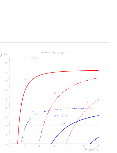
It can be seen that the aerogel will allow for good pion/proton separation up to 4 GeV/c, while the aerogel material can be used for pion/kaon separation in the momentum range 1-3 GeV/c, and for pion/proton separation up to 6 GeV/c.
Note that the number of photoelectrons (Npe ) produced just above the proton (kaon) threshold is much lower for protons (kaons) than for pions, which allows for limited particle identification just above threshold by counting Npes.
To obtain the required total thickness and effective area of most aerogel detectors, they need to be comprised of a large number of the typically smaller-size tiles. Thus, the uniformity of the optical quality and the tolerance from tile to tile becomes important.
Aerogels commercially available from Matsushita Electric Works Ltd (Japan) [9] are highly transparent and have a light output which is almost linear with the radiator thickness. They are known to be of high quality. For example, the detailed study of about 1000 tiles of the Matsushita aerogel produced for the HERMES experiment [7] shows that their mean refractive indexes are in the range, with only small variation from tile to tile.
The improved light transmittance and hydrophobicity of this “new” aerogel material is due to a new production technique [7, 10], and makes it preferable to the early hydrophilic aerogel materials that needed baking and storage in a dry nitrogen atmosphere to maintain the initial good transmittance of the radiator [11].
Although the light transmittance of aerogel is relatively small, the light absorption is also rather small [7]. Hence, a large number of photons undergo multiple scattering and lose directionality but do eventually reach a photo detector. Diffuse light collection by means of highly reflective walls, also known as a “diffusion box”, seems a good choice.
3 The Aerogel detector
3.1 Physical design
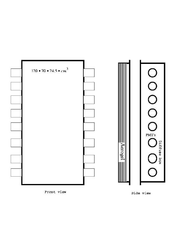
There are different schemes for collecting Cherenkov light. In our detector we make use of a diffusion box. The photon detection probability in the case of a diffusion box is directly proportional to the fraction of detector surface covered by PMTs.An increase in the area covered by PMTs results in an increase of the number of photons detected. As a result, and as shown by Monte Carlo calculations, we used 16 PMTs in the counter. The aerogel detector schematic design is shown in Fig. 2. It is a sandwich of an aerogel tray and a diffusion light box with PMTs. This allows for simple detector assembly and easy replacement of the aerogel stack. The active area is 12070 cm2. Eight PMTs are mounted on both “long” sides of the box. The total area covered by the photo-cathode windows of these PMTs amounts to 8% of the inner surface of the counter. Of course, it is important to have high reflectivity for the inner walls of the diffusion box. To accomplish this, the inner walls of the diffusion box were covered with millipore paper “Membrane GSWP-0010” (reflectivity 96%) [12].
A Monte Carlo simulation for the HMS aerogel detector was done using a technique to simulate diffusely reflective aerogel Cherenkov detectors [8]. The detector active area was taken as 1207024.5 cm3 and 5 inch PMTs with a 20% quantum efficiency were used as starting point. Several options were considered for the detector:
-
-
readout with PMTs from one and two sides of the diffusion box;
-
-
the number (5 or 8) of PMTs at each side;
-
-
two different thicknesses of aerogel, 5 and 9 cm, respectively.
As anticipated, the best uniformity of the summed Npe signal (flat within 10%) was found for the two-side readout. The mean number of photoelectrons for 5 cm thickness aerogel of was predicted to be 6.6 for 10 PMT readout and 8.3 when 16 PMTs (8 PMT’s from each side) were used. As a result of the high optical quality of the aerogel material under consideration the number of photoelectrons increased roughly linearly with the aerogel thickness. The simulated mean number of photoelectrons for the same type of aerogel of 9 cm thickness was predicted to be 12.1 for the 10 PMT readout case and 14.8 for the 16 PMT case.
We estimated that the use of a detector with aerogel material of 9 cm thickness and with a 2 mm total Al thickness for entrance and exit windows would double the number of - electron produced, which could reach 2% for HMS detector stack at momentum GeV/c.
We used 16 ten-stage Photonis XP4572B PMTs of 5 inch diameter, with a bialkali photo-cathode and a maximum gain of 107. These PMTs have a quantum efficiency 20% in the wavelength range 350-450 nm, which well matches the transmitted radiation spectrum of aerogel. Due to an enhanced photoelectron collection efficiency the effective number of photoelectrons can be increased by a factor of 2 relative to more commonly used PMTs such as the Burle 8854 [14].
The close spacing of the metal shields (to improve the light collection efficiency) required us to keep the cathode at ground potential, while positive high voltage was applied to the anode of the PMT to reduce the noise level. To compensate for the low gain of the chosen PMT, we modified their High Voltage (HV) bases by inserting an amplifier in the HV dividers as a sequential component after the last resistor. The fast amplifier was designed [15] for standby operation at relatively low currents with a signal charge amplification factor of 10. It allows us to operate the PMTs at lower high voltages, hence prolonging their lifetimes.
Two identical boxes were fabricated for the aerogel trays, one each for the and materials. Both match the common diffusion box and can be easily substituted for each other.
Matsushita produces aerogel in the form of mm3 tiles. In order to stack the material, each tile dimension was first measured and the differences in block sizes determined. Taking into account the tolerances on the actual aerogel material thickness inside the diffusion boxes, the tiles were layered in 9 stacks in the case of , and 8 stacks in the case of . In both cases the total thickness of aerogel radiator was 9 cm, using over 650 tiles for each box. To prevent any stress on the aerogel material from the front side of the detector, the aerogel tiles were stacked in a thin (5mm) honeycomb sheet and housed in a tray of dimensions 11767 cm2. The layers were shifted relative to each other by about 2-3 cm to prevent any dead zones inside the aerogel volume.
The stacks of aerogel tiles are kept in position by means of a mesh of thin (100 m) stainless steel wire.
4 Calibration of the photo multiplier tubes
The calibration of the 16 PMTs consists of evaluating the average number of detected photoelectrons and distributing them efficiently over the aerogel detector. The preliminary calibration of each PMT was performed by measuring the PMT response to a pulsed light source. The light intensity from the Light Emitting Diode (LED) used was controlled by adjustment of the height and width of the applied pulses. For each PMT the Single Photo-Electron peak position and its width were found versus the applied high voltage. This allowed us to roughly equalize the response functions for all PMTs, and to determine their gains at a given high voltage.
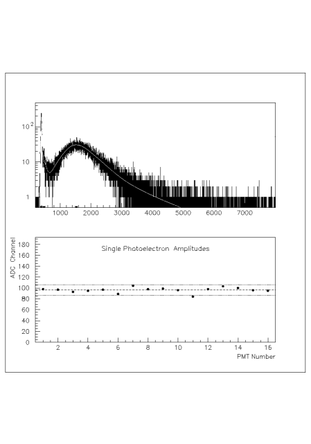
A preliminary test of the aerogel detector was performed with cosmic rays. The detector was positioned horizontally with the diffusion box on top. A pair of scintillators sandwiched the aerogel detector, with a third one separated by a layer of lead bricks. This lead absorber was used to select the energy of cosmic muons (the threshold momentum of muons firing the aerogel detector is 430 MeV/c). The DAQ system was a simplified version of the standard DAQ system of Hall C [16].The cosmic test was used to roughly adjust the PMT high voltages and estimate the number of photoelectrons from cosmic muons. Both a typical pulse height spectrum summed over the 16 tubes, and the single photo-electron positions (in ADC channels) for all the tubes after gain matching, are presented in Fig. 3.
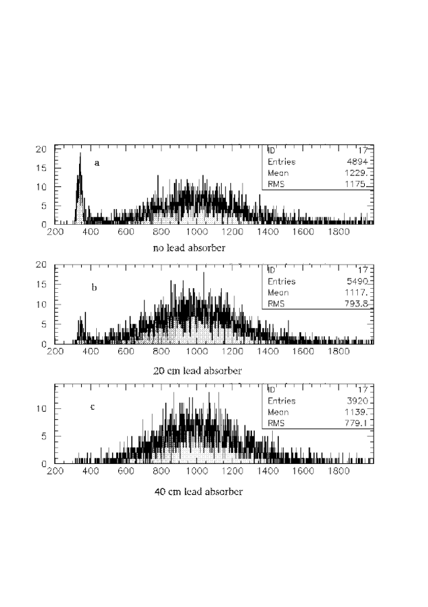
The ability of the aerogel Cherenkov detector to distinguish between cosmic muons above and below detection threshold is illustrated in Fig. 4, where the pulse height spectrum summed over the 16 PMTs is shown for several thicknesses of the lead absorber. The use of the lead absorber between the second and third trigger counters clearly allows the low-energy part of the muon spectrum to be cut off. This is reflected in the figure as the diminishing of the pedestal events with the increase of the lead absorber thickness.
5 Experimental results with beam
The aerogel detector was installed and integrated into the Hall C data acquisition system, and subsequently successfully used in the Hall C experimental program of 2003. In this section we will show the results obtained with the aerogel detector, for both indices of refraction, with beam.
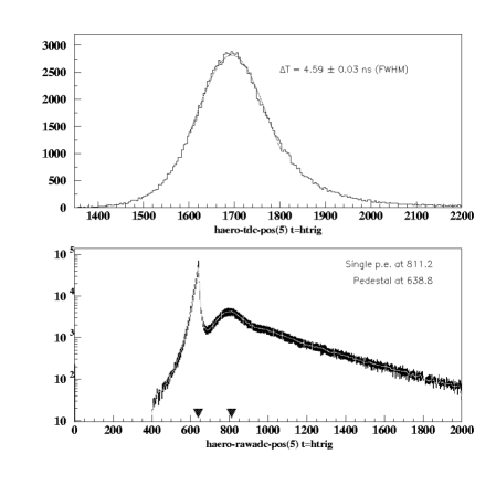
Fig. 5 shows typical TDC and ADC raw spectra for one of the aerogel PMTs. Although a 4 ns (FWHM) time resolution is not very good (it is mainly due to the large spread in light paths through the diffusion box), information from the TDC was still useful in the off-line analysis for additional rejection of accidental events in the summed aerogel signal at high rates. One can see a clean separation of the single photo-electron peak from pedestals in the ADC spectrum. The two photo-electron peak is also, but barely, distinguishable. A smooth fit to such ADC spectra provides pedestal and single photo-electron peak positions for each PMT. These are then used for detector calibration purposes.
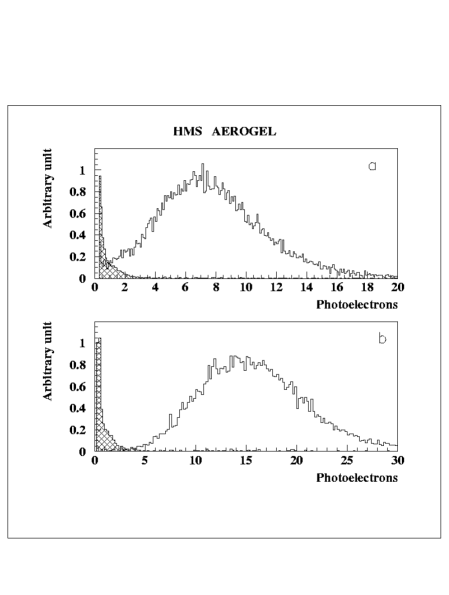
In Fig. 6 the distribution of the total number of photo-electrons Npe (for all PMTs summed) for the aerogel detector with (top) and (bottom), respectively, are shown for protons and pions at 3.1 GeV/c. The signal from the pions is nearly in saturation, while the signal from protons at this momentum is still below detection threshold. The mean values of the number of photo-electrons (in saturation) are 16 for the and 8 for the aerogels, respectively.
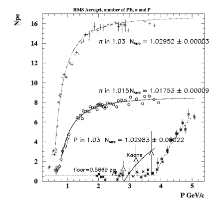
The experimental data over a wide range of momenta, from 0.5 GeV/c to 4 GeV/c, for different types of particles show that the dependence of Npe upon momentum has the expected threshold behavior, and that the number of photo-electrons indeed saturates at high momentum (see Fig. 7).
When the detector is used in threshold mode, or when one would like to estimate the threshold velocity of a particle in the given aerogel (or, alternatively, the index of refraction of the material), it is important to know the response for particles below the Cherenkov threshold. The 0.6 photo-electron background (for the 16 PMTs summed) shown in Fig. 7 may come from the following sources [13]:
-
-
-electrons with momentum above detection threshold;
-
-
accidental events not rejected by the trigger;
-
-
particles causing Cherenkov light or scintillation in the millipore paper or the air in the diffusion box.
After subtraction of this background, one can evaluate the index of refraction of the used aerogel material from a fit to the data shown in Fig. 7. The calculated and real values of index of refraction for both aerogels match well, although better in the case of the aerogel with .
.
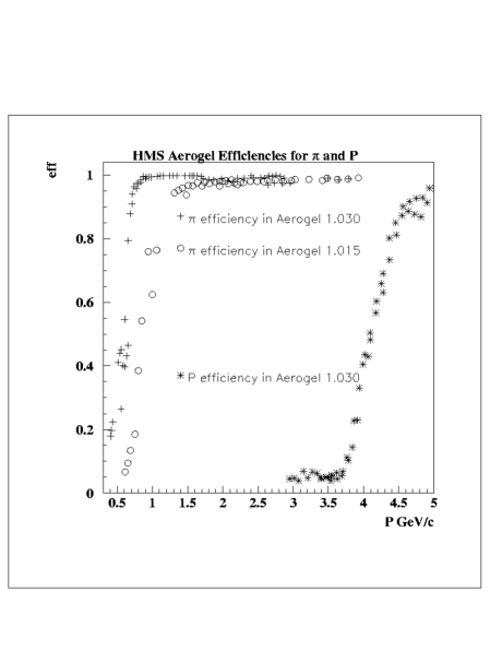
From these Npe data the detector efficiency versus momentum can be determined. This results in an efficiency for pion detection in the aerogel with of more than 99%, in the 1-4 GeV/c momentum range (N). For the case of the aerogel material with , the pion detection efficiency is more than 97%, assuming a cut level of N2, in a 1.2-4 GeV/c momentum range (see Fig. 8).
One of the most important features of any detector is the near independence of its response function to position.As shown in Figs. 9 , 10 and 11, the total sum of photo-electrons detected by the aerogel detector has a near flat distribution both in the vertical (X) and horizontal (Y) direction . Not surprisingly, close to the PMTs some enhancement can be seen in the number of photo-electrons detected. Similarly, in Fig. 12 the response function versus the spectrometer fractional momentum (10%) is shown. There is no significant dependence over the full momentum acceptance of the HMS.
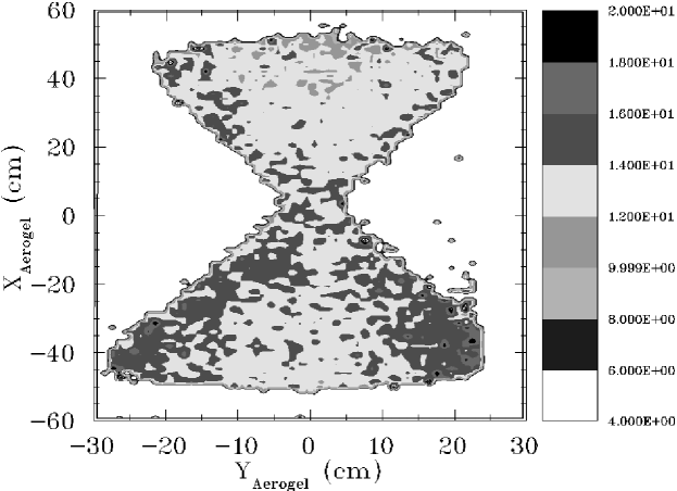
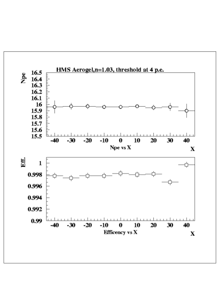
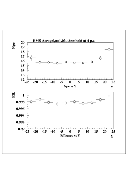
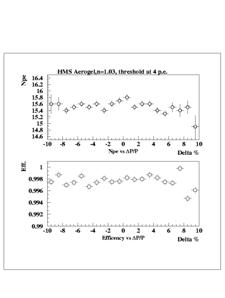
Note that for these last cases a cut of was used to provide more than 99% detection efficiency for the () aerogel detector. The aerogel material with index of refraction () shows a similar behavior, but with less detection efficiency (97% for a cut condition).
The long-term stability of the HMS aerogel detector was tested during experimental runs in Hall C over a 6-month period. The mean number of photo-electrons for the summed detector signals remained stable to within 2%, with a typical particle rate of 500-600 kHz.
Our studies show that, for an aerogel detector with () where kaons cross detection threshold at a momentum of 2.8 GeV/c, it is more efficient to use the aerogel detector to reject kaons than to select them. The number of photo-electrons generated by these kaons is about 4, for a momentum up to 4 GeV/c, as shown in Fig. 1 and Fig. 7. Applying a cut in Npe of 2 rejects of kaons at a momentum P = 3.7 GeV/c, while the same cut rejects only of kaons at a momentum of 2.4 GeV/c (below threshold).
6 Conclusions
The particle identification properties of the HMS spectrometer in Hall C at Jefferson Lab have been significantly improved by adding a flexible aerogel threshold Cherenkov detector. The detector consists of an aerogel material followed by a light diffusion box. The radiator tray can easily be swapped for an alternate one with aerogel material with different index of refraction. The addition of this detector enhanced the capabilities of the spectrometer in distinguishing protons from pions on the level of (for aerogel with ) with a pion detection efficiency better than 99% in the 1-4 GeV/c momentum range. It allowed the distinction of kaons from pions on the level of , for aerogel with , with a pion detection efficiency better than 97% in a 1.2-4 GeV/c momentum range. The mean numbers of detected photo-electrons are 16 and 8 for the and aerogel material, respectively. The detector response is uniform to within 10% over the full effective area. The experimental results are in good agreement with expected values from simulations using a standard Monte Carlo program for aerogel detectors [8]. The number of fake photo-electrons for particles below detection threshold reaches 0.6, which may be a result of -electrons,accidental events or scintilations of particles traversing the detector.
We wish to thank many people who assisted and contributed in the design, construction and testing of this detector. We are particularly indebted to R. Carlini for support to construct such a detector, D. Higinbotham for assistance and providing access to his Monte Carlo simulation program for Aerogel detectors, B. Wojtsekhowski for interest and many useful discussions, C. Zorn for valuable contributions to the systematic tests of the PMTs, V. Popov for the development of the PMT amplifier and the installation of these in the HV bases, W. Kellner and his group for their technical expertise and help with the installation of the aerogel detector and the aerogel radiator replacement in Hall C. Lastly, many thanks to J. Beaufait for continuous help during all stages of the construction and the preliminary testing.
The Southeastern Universities Research Association (SURA) operates the Thomas Jefferson National Accelerator Facility for the United States Department of Energy under contract DE-AC05-84ER40150.
References
- [1] Conceptual Design Report - Basic Experimental Equipment, CEBAF,. Newport News, Virginia, April 13,. 1990
- [2] TJNAF Experiment E01-002, P. Bosted, V. Frolov, M. Jones, V. Koubarovski and P. Stoler spokespersons
- [3] TJNAF Experiment E01-104, H. Blok, G. Huber, D. Mack spokespersons
- [4] TJNAF Experiment E00-108, R. Ent, H. Mkrtchyan, G. Niculescu spokespersons
- [5] D. E. Groom et al., Eur. Phys.J. C 3, (1998) 150
- [6] H. Yokogawa and M. Yokoyama, Hydrophobic Silica aerogels. Jurnal of Non-Crystalline Solids, 186 (1995)
- [7] E. Aschenauer, N. Bianchi, G. Capitani et al., Nucl. Inst. and Meth. A 440 (2000) 338
- [8] D.Higinbotham, Nucl. Inst. and Meth. A 414(1998) 332
- [9] Matsushita Electric Works, 1048 Kadoma, Kadoma-shi, Osaka 571, Japan
- [10] I. Adachi et.al., Nucl. Inst. and Meth. A 355 (1995) 390
- [11] R. Mohring, Ph.D. Thesis. University of Maryland, 1999; and http://www.jlab.org/Hall-C
- [12] Millipore Corporation, 80 Ashly Road, Bedford, MA 01730. http://www.millipore.com/.
- [13] D. Barancourt et.al., Nucl. Inst.and Meth. A 465 (2001) 306, and Y. Asaoka et.al., Nucl. Inst.and Meth. A 416 (1998) 236
- [14] B.Wojtsekhowski, C.Zorn and S.Flyckt, Evaluation of new 5 inch PMT for use in threshold Cherenkov detectors with aerogel radiator. Transactions of the 2000 IEEE Nuclear Science Symposium, Lyons, France, Oct.15-20 (2000) pp 7-63 - 7-65 .
- [15] V.Popov, JLab Detector Group Internal Reports and private communication.
- [16] Hall C Analysis Documentation. http://www.jlab.org/Hall-C