Neutrino Factory and Beta Beam Experiments and Development
Abstract
The long-term prospects for fully exploring three-flavor mixing in the neutrino sector depend upon an ongoing and increased investment in the appropriate accelerator R&D. Two new concepts have been proposed that would revolutionize neutrino experiments, namely the Neutrino Factory and the Beta Beam facility. These new facilities would dramatically improve our ability to test the three-flavor mixing framework, measure CP violation in the lepton sector, and perhaps determine the neutrino mass hierarchy, and, if necessary, probe extremely small values of the mixing angle . The stunning sensitivity that could be achieved with a Neutrino Factory is described, together with our present understanding of the corresponding sensitivity that might be achieved with a Beta Beam facility. In the Beta Beam case, additional study is required to better understand the optimum Beta Beam energy, and the achievable sensitivity. Neither a Neutrino Factory nor a Beta Beam facility could be built without significant R&D. An impressive Neutrino Factory R&D effort has been ongoing in the U.S. and elsewhere over the last few years and significant progress has been made towards optimizing the design, developing and testing the required accelerator components, and significantly reducing the cost. The recent progress is described here. There has been no corresponding activity in the U.S. on Beta Beam facility design and, given the very limited resources, there is little prospect of starting a significant U.S. Beta Beam R&D effort in the near future. However, the Beta Beam concept is interesting, and progress on its development in Europe should be followed. The Neutrino Factory R&D program has reached a critical stage in which support is required for two crucial international experiments and a third-generation international design study. If this support is forthcoming, a Neutrino Factory could be added to the Neutrino Community’s road map in about a decade.
Preface
In response to the remarkable recent discoveries in neutrino physics, the APS Divisions of Particles and Fields, and of Nuclear Physics, together with the APS Divisions of Astrophysics and the Physics of Beams, have organized a year long Study on the Physics of Neutrinos aps (2004) that began in the fall of 2003. Within the context of this study, the Neutrino Factory and Beta Beam Experiments and Development Working Group was charged with reviewing, and if possible advancing, our understanding of the physics capabilities and design issues for these two new types of future neutrino facilities. To fulfill this charge, the working group conducted a Workshop at ANL March 3–4, 2004. The presentations and discussion at this Neutrino Factory and Beta Beams Workshop, together with the Neutrino Factory Design work of the Neutrino Factory and Muon Collider Collaboration MC , form the basis for this report. Over the last few years, there have been a series of workshops that have explored the design and physics capabilities of Neutrino Factories. These meetings include the international NUFACT Workshop series N. Autin, ed. (2000); S. Chattopadhyay, ed. (2001); S. Machida and K. Yoshimura, eds. (2003); K. Long and R. Edgecock, eds. (2003); nuf , many smaller, more specialized, workshops focused on specific parts of Neutrino Factory design and technology, and two more detailed Feasibility Studies N. Holtkamp and D. Finley, eds. (2000); S. Ozaki, R. Palmer, M. Zisman, and J. Gallardo, eds. (2001). In addition, a large body of literature documents the physics motivation for Neutrino Factories and the progress that has been made towards realizing this new type of neutrino facility. The Neutrino Factory related goals for the working group were therefore to (i) review and summarize the results of the extensive work already done, and (ii) to update the picture utilizing the design study resources of the Neutrino Factory and Muon Collider Collaboration, and the latest results from those making detailed studies of the physics capabilities of Neutrino Factories. The Beta Beam concept is several years younger than the Neutrino Factory concept, and the community’s understanding of both the physics capabilities and the required design parameters (particularly the beam energy) is still evolving. Beta Beam R&D is being pursued in Europe, but there is no significant Beta Beam R&D activity in the U.S. Hence, Beta Beam related goals of the working group were necessarily more modest than the equivalent Neutrino Factory related goals. We restricted our ambitions to reviewing the evolving understanding of the physics reach coming out of work from Beta Beam proponents in Europe, and the R&D challenges that must be met before a Beta Beam facility could be built. Possibilities for Neutrino Factory and Beta Beam facilities seem to have caught the imagination of the community. We hope that this report goes some way towards documenting why, and what is required to make these new and very promising neutrino tools a reality.
Steve Geer and Mike Zisman
I Introduction
Neutrino Factory Geer (1998); M. M. Alsharo´a et al. (2003); A. Blondel et al. and Beta Beam Zucchelli (2002) facilities offer two exciting options for the long-term neutrino physics program. In the U.S. there has been a significant investment in developing the concepts and technologies required for a Neutrino Factory, but no equivalent investment in developing Beta Beams. In the following we consider first the Neutrino Factory, and then the Beta Beam case.
New accelerator technologies offer the possibility of building, in the not-too-distant future, an accelerator complex to produce and capture more than muons per year M. M. Alsharo´a et al. (2003). It has been proposed to build a Neutrino Factory by accelerating the muons from this intense source to energies of several tens of GeV, injecting them into a storage ring having long straight sections, and exploiting the intense neutrino beams that are produced by muons decaying in the straight sections. The decays
| (1) |
offer exciting possibilities to pursue the study of neutrino oscillations and neutrino interactions with exquisite precision.
To create a sufficiently intense muon source, a Neutrino Factory requires an intense multi-GeV proton source capable of producing a primary proton beam with a beam power of 1 MW or more on target. This is just the proton source required in the medium term for Neutrino Superbeams. Hence, there is a natural evolution from Superbeam experiments in the medium term to Neutrino Factory experiments in the longer term.
The physics case for a Neutrino Factory will depend upon results from the next round of planned neutrino oscillation experiments. If the unknown mixing angle is small, such that , or if there is a surprise and three-flavor mixing does not completely describe the observed phenomenology, then answers to some or all of the most important neutrino oscillation questions will require a Neutrino Factory. If is large, just below the present upper limit, and if there are no experimental surprises, the physics case for a Neutrino Factory will depend on the values of the oscillation parameters, the achievable sensitivity that will be demonstrated by the first generation of appearance experiments, and the nature of the second generation of basic physics questions that will emerge from the first round of results. In either case (large or small ), in about a decade the neutrino community may need to insert a Neutrino Factory into the global neutrino plan. The option to do this in the next 10–15 years will depend upon the accelerator R&D that is done during the intervening period.
In the U.S., the Neutrino Factory and Muon Collider Collaboration (referred to herein as the Muon Collaboration, or MC) MC is a collaboration of 130 scientists and engineers devoted to carrying out the accelerator R&D that is needed before a Neutrino Factory could be inserted into the global plan. Much technical progress has been made over the last few years, and the required key accelerator experiments are now in the process of being proposed and approved. The 2001 HEPAP subpanel HEP (2000) recommended a level of support that is sufficient to perform the critical accelerator R&D during the next 10–15 years. This support level significantly exceeds the present investment in Neutrino Factory R&D. In addition to the U.S. effort, there are active Neutrino Factory R&D groups in Europe UK , CER and Japan JAP , and much of the R&D is performed and organized as an international endeavor. Thus, because a Neutrino Factory is potentially the key facility for the long-term neutrino program, Neutrino Factory R&D is an important part of the present global neutrino program. Indeed, the key R&D experiments are seeking funding now, and will need to be supported if Neutrino Factories are to be an option for the future.
Consider next Beta Beam facilities Zucchelli (2002), B. Autin et al. (2003). It has been proposed to modify the Neutrino Factory concept by injecting beta-unstable radioactive ions, rather than muons, into a storage ring with long straight sections. This would produce a pure or beam, depending on the stored ion species. The very low Q value for the decay means that the resulting neutrino beam will have a very small divergence, but it also means that the parent ions must be accelerated to high energies to produce neutrinos with even modest energies. The baseline Beta Beam concept involves accelerating the radioactive ions in the CERN SPS, which yields neutrino beams with energies of a few hundred MeV. The sensitivity of these Beta Beams to small values of appears to be comparable with the ultimate sensitivity of Superbeam experiments. Better performance might be achieved with higher energy Beta Beams, requiring the ions to be accelerated to at least TeV energies. This requires further study. This R&D is currently being pursued in Europe, where the proponents hope that a Beta Beam facility together with a Superbeam at CERN and a very massive water Cerenkov detector in the Fréjus tunnel, would yield a very exciting neutrino program.
In this report, we summarize the expected sensitivities of Neutrino Factory and Beta Beam neutrino oscillation experiments, and the status of the R&D required before these exciting facilities could become a part of the neutrino community’s global plan. Exploiting the enthusiastic involvement of the Muon Collaboration in the study, we also describe an updated Neutrino Factory design that demonstrates significant progress toward cost reduction for this ambitious facility. The report is organized as follows. Section II describes in some detail the Neutrino Factory and Beta Beam design concepts. In Section III, Neutrino Factory and Beta Beam properties are described and compared with conventional neutrino beams. The neutrino oscillation physics reach is presented in Section IV. Progress on Neutrino Factory designs along with some comments on the possibility of a U.S.-based Beta Beam facility are discussed in Section V. The Neutrino Factory and Beta Beam R&D programs are described in Section VI. A summary is given in Section VII and some recommendations are presented in Section VIII. Finally, in Appendix A a cost scaling with respect to the Feasibility Study-II cost numbers is presented.
II Machine Concepts
In this Section we describe the basic concepts that are used to create a Neutrino Factory or a Beta Beam facility. Though the details of the two facilities are quite different, many of the required features have common origins. Both facilities are “secondary beam” machines, that is, a production beam is used to create the secondary beam that eventually provides the neutrino flux for the detector.
For a Neutrino Factory, the production beam is a high intensity proton beam of moderate energy (beams of 2–50 GeV have been considered by various groups) that impinges on a target, typically a high- material. The collisions between the proton beam and the target nuclei produce a secondary pion beam that quickly decays into a longer-lived (2.2 s) muon beam. The remainder of the Neutrino Factory is used to condition the muon beam (see Section II.1), accelerate it rapidly to the desired final energy of a few tens of GeV, and store it in a decay ring having a long straight section oriented such that decay neutrinos produced there will hit a detector located thousands of kilometers from the source.
A Beta Beam facility is one in which a pure electron neutrino or antineutrino beam is produced from the decay of beta unstable radioactive ions circulating in a storage ring. As was the case for the Neutrino Factory, current Beta Beam facility concepts are based on using a proton beam to hit a layered production target. In this case, nuclear reactions are used to produce secondary particles of a beta-unstable nuclide. The proposed approach uses either spallation neutrons from a high- target material or the incident protons themselves to generate the required reactions in a low- material. The nuclide of interest is then collected, ionized, accumulated, and accelerated to its final energy. The process is relatively slow, but this is acceptable as the lifetimes of the required nuclides, of order 1 s, are sufficiently long.
II.1 Neutrino Factory
The various components of a Neutrino Factory, based in part on the most recent Feasibility Study (Study-II, referred to herein as FS2) S. Ozaki, R. Palmer, M. Zisman, and J. Gallardo, eds. (2001) that was carried out jointly by BNL and the U.S. Neutrino Factory and Muon Collider Collaboration, are described briefly below. Details of the design discussed here are based on the specific scenario of sending a neutrino beam from BNL to a detector in Carlsbad, New Mexico. More generally, however, the design exemplifies a Neutrino Factory for which two Feasibility Studies N. Holtkamp and D. Finley, eds. (2000); S. Ozaki, R. Palmer, M. Zisman, and J. Gallardo, eds. (2001) have demonstrated technical feasibility (provided the challenging component specifications are met), established a cost baseline, and established the expected range of physics performance. It is worth noting that the Neutrino Factory design we envision could fit comfortably on the site of an existing laboratory, such as BNL or FNAL. As part of the current Study, we have developed improved methods for accomplishing some of the needed beam manipulations. These improvements are included in the description below.
The main ingredients of a Neutrino Factory include:
-
•
Proton Driver: Provides 1–4 MW of protons on target from an upgraded AGS; a new booster at Fermilab would perform equivalently.
-
•
Target and Capture: A high-power target immersed in a 20 T superconducting solenoidal field to capture pions produced in proton-nucleus interactions. The high magnetic field at the target is smoothly tapered down to a much lower value, 1.75 T, which is then maintained through the bunching and phase rotation sections of the Neutrino Factory.
-
•
Bunching and Phase Rotation: We first accomplish the bunching with rf cavities of modest gradient, whose frequencies change as we proceed down the beam line. After bunching the beam, another set of rf cavities, with higher gradients and again having decreasing frequencies as we proceed down the beam line, is used to rotate the beam in longitudinal phase space to reduce its energy spread.
-
•
Cooling: A solenoidal focusing channel, with high-gradient 201.25 MHz rf cavities and LiH absorbers, cools the transverse normalized rms emittance from 17 mmrad to about 7 mmrad. This takes place at a central muon momentum of 220 MeV/c.
-
•
Acceleration: A superconducting linac with solenoidal focusing is used to raise the muon beam energy to 1.5 GeV, followed by a Recirculating Linear Accelerator (RLA), arranged in a “dogbone” geometry, to provide a 5 GeV muon beam. Thereafter, a pair of cascaded Fixed-Field, Alternating Gradient (FFAG) rings, having quadrupole triplet focusing, is used to reach 20 GeV. Additional FFAG stages could be added to reach a higher beam energy, if the physics requires this.
-
•
Storage Ring: We employ a compact racetrack-shaped superconducting storage ring in which % of the stored muons decay toward a detector located some 3000 km from the ring. Muons survive for roughly 500 turns.
II.1.1 Proton Driver
The proton driver considered in FS2, and taken here as well, is an upgrade of the BNL Alternating Gradient Synchrotron (AGS) and uses most of the existing components and facilities; parameters are listed in Table 1. To serve as the proton driver for a Neutrino Factory, the existing booster would be replaced by a 1.2 GeV superconducting proton linac. The modified layout is shown in Fig. 1.
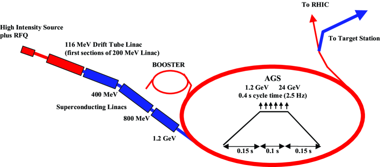
The AGS repetition rate would be increased from 0.5 Hz to 2.5 Hz by adding power supplies to permit ramping the ring more quickly. No new technology is required for this—the existing supplies would be replicated and the magnet strings would be split into six sectors rather than the two used presently. The total proton charge ( ppp in six bunches) is only 40% higher than the current performance of the AGS. However, the bunches required for a Neutrino Factory are shorter than those used in the AGS at present, so there is a large increase in peak current and concomitant need for an improved vacuum chamber; this is included in the upgrade. The six bunches are extracted separately, spaced by 20 ms, so that the target and rf systems that follow need only deal with single bunches at an instantaneous repetition rate of 50 Hz (average rate of 15 Hz). The average proton beam power is 1 MW. A possible future upgrade to ppp and 5 Hz could give an average beam power of 4 MW. At this higher intensity, a superconducting bunch compressor ring would be needed to maintain the rms bunch length at 3 ns.
If the facility were built at Fermilab, the proton driver would be newly constructed. A number of technical options are presently being explored fna (2000),fna (2002).
| AGS | |
|---|---|
| Total beam power (MW) | 1 |
| Beam energy (GeV) | 24 |
| Average beam current (A) | 42 |
| Cycle time (ms) | 400 |
| Number of protons per fill | |
| Average circulating current (A) | 6 |
| No. of bunches per fill | 6 |
| No. of protons per bunch | |
| Time between extracted bunches (ms) | 20 |
| Bunch length at extraction, rms (ns) | 3 |
II.1.2 Target and Capture
A mercury-jet target is chosen to give a high yield of pions per MW of incident proton power. The 1-cm-diameter jet is continuous, and is tilted with respect to the beam axis. The target layout is shown in Fig. 2.
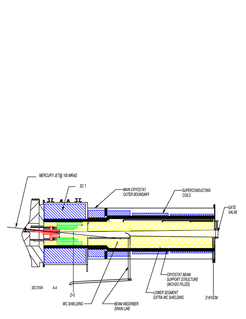
We assume that the thermal shock from the interacting proton bunch fully disperses the mercury, so the jet must have a velocity of 20–30 m/s to allow the target material to be renewed before the next proton bunch arrives. Calculations of pion yields that reflect the detailed magnetic geometry of the target area have been performed with the MARS code Mokhov (2001) and are reported in Section V. The FS2 design was updated for the present study to improve muon throughput. To avoid mechanical fatigue problems, a mercury pool serves as the beam dump. This pool is part of the overall target system—its mercury is circulated through the mercury jet nozzle after passing through a heat exchanger. Pions emerging from the target are captured and focused down the decay channel by a solenoidal field that is 20 T at the target center, and tapers down, over 12 m, to 1.75 T. The 20 T solenoid, with a resistive magnet insert and superconducting outer coil, is similar in character to higher field (up to 45 T), but smaller bore, magnets existing at several laboratories J.R. Miller et al. (1994). The magnet insert is made with hollow copper conductor having ceramic insulation to withstand radiation. MARS simulations N. Mokhov of radiation levels show that, with the shielding provided, both the copper and superconducting magnets will have reasonable lifetime.
II.1.3 Buncher and Phase Rotation
Pions, and the muons into which they decay, are generated in the target over a very wide range of energies, but in a short time pulse ( ns rms). To prepare the muon beam for acceleration thus requires significant “conditioning.” First, the bunch is drifted to develop an energy correlation, with higher energy particles at the head and lower energy particles at the tail of the bunch. Next, the long bunch is separated into a number of shorter bunches suitable for capture and acceleration in a 201-MHz rf system. This is done with a series of rf cavities having frequencies that decrease along the beam line, separated by suitably chosen drift spaces. The resultant bunch train still has a substantial energy correlation, with the higher energy bunches first and progressively lower energy bunches coming behind. The large energy tilt is then “phase rotated”, using additional rf cavities and drifts, into a bunch train with a longer time duration and a lower energy spread. The beam at the end of the buncher and phase rotation section has an average momentum of about 220 MeV/c. The proposed system is based on standard rf technology, and is expected to be much more cost effective than the induction-linac-based system considered in Ref. S. Ozaki, R. Palmer, M. Zisman, and J. Gallardo, eds. (2001). A fringe benefit of the rf-based system is the ability to transport both signs of muon simultaneously.
II.1.4 Cooling
Transverse emittance cooling is achieved by lowering the beam energy in LiH absorbers, interspersed with rf acceleration to keep the average energy constant. Both transverse and longitudinal momenta are lowered in the absorbers, but only the longitudinal momentum is restored by the rf system. The emittance increase from Coulomb scattering is controlled by maintaining the focusing strength such that the angular spread of the beam at the absorber locations is reasonably large. In the present cooling lattice, the energy absorbers are attached directly to the apertures of the rf cavity, thus serving the dual purposes of closing the cavity apertures electromagnetically (increasing the cavity shunt impedance) and providing energy loss. Compared with the approach used in FS2, the absorbers are more distributed, and do not lend themselves to being located at an optical focus. Therefore, the focusing is kept essentially constant along the cooling channel, but at a beta function somewhat higher than the minimum value achieved in FS2. A straightforward Focus-Focus (FOFO) lattice is employed. The solenoidal fields in each half-cell alternate in sign, giving rise to a sinusoidal field variation along the channel. Use of solid absorbers instead of the liquid-hydrogen absorbers assumed in FS2 will considerably simplify the cooling channel, and the new magnet requirements are also more modest, since fewer and weaker components are needed compared with FS2. Together, these features reduce the cost of the cooling channel with respect to the FS2 design. Although the cooling performance is reduced, the overall throughput is comparable to that in FS2 due to the increased acceptance built into the downstream acceleration system. Here too, the ability to utilize both signs of muon is available.
II.1.5 Acceleration
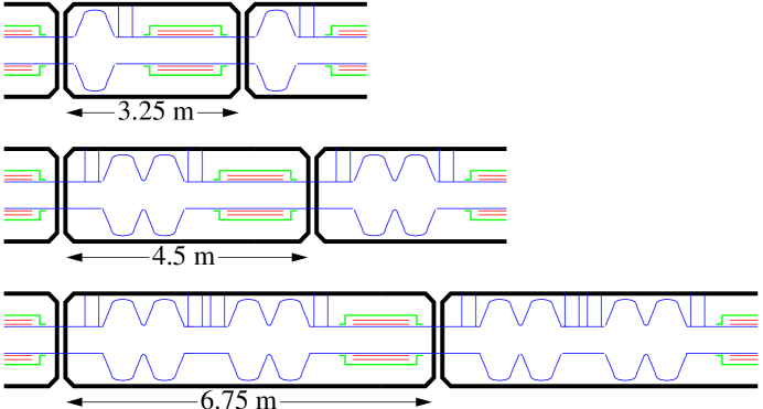
Parameters of the acceleration system are listed in Table 2. A matching section, using normal conducting rf systems, matches the cooling channel optics to the requirements of a superconducting rf linac with solenoidal focusing which raises the energy to 1.5 GeV. The linac is in three parts (see Section V.2). The first part has only a single-cell 201 MHz cavity per period. The second part, with longer period, has a 2-cell rf cavity unit per period. The third part, as a still longer period becomes possible, accommodates two 2-cell cavity units per period. Figure 3 shows the three cryomodule types that make up the pre-accelerator linac.
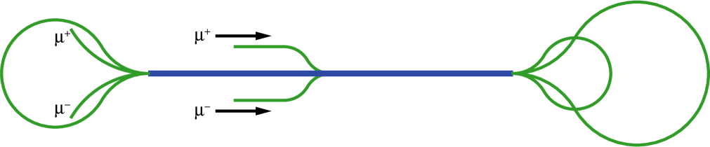
This linac is followed by a 3.5-pass dogbone RLA (see Fig. 4) that raises the energy from 1.5 to 5 GeV. The RLA uses four 2-cell superconducting rf cavity structures per cell, and utilizes quadrupole triplet (as opposed to solenoidal) focusing.
Following the RLA are two cascaded FFAG rings that increase the beam energy from 5–10 GeV, and 10–20 GeV, respectively. Each ring uses combined-function magnets arranged in a triplet (F-D-F) focusing arrangement. The lower energy FFAG ring has a circumference of about 400 m; the higher energy ring is about 500 m in circumference. As discussed in Section V.2, an effort was made to achieve a reasonably cost-optimized design. Without detailed engineering, it is not possible to fully optimize costs, but we have employed general formulae that properly represent the cost trends and that were considered adequate to make choices at the present stage of the design. As the acceleration system was one of the dominant cost items in FS2, we are confident that the approach adopted here will result in a less expensive Neutrino Factory facility with essentially the same performance as calculated for the FS2 design. Achieving a higher beam energy would require additional FFAG acceleration stages.
| Injection momentum (MeV/c) | 273 |
| Injection kinetic energy (MeV) | 187 |
| Final total energy (GeV) | 20 |
| Initial normalized acceptance (mm-rad) | 30 |
| rms normalized emittance (mm-rad) | 3.84 |
| Initial longitudinal acceptance, (mm) | 150 |
| Total energy spread, (MeV) | |
| Total time-of-flight (ns) | |
| rms energy spread (MeV) | 19.8 |
| rms time-of-flight (ns) | 0.501 |
| Number of bunches per pulse | 89 |
| Peak number of particles per bunch | |
| Number of particles per pulse (per charge) | |
| Bunch frequency/accelerating frequency (MHz) | 201.25/201.25 |
| Average beam power (per charge) (kW) | 144 |
II.1.6 Storage Ring
After acceleration in the final FFAG ring, the muons are injected into the upward-going straight section of a racetrack-shaped storage ring with a circumference of 358 m. Parameters of the ring are summarized in Table 3. High-field superconducting arc magnets are used to minimize the arc length and maximize the fraction (35%) of muons that decay in the downward-going straight, generating neutrinos headed toward the detector located some 3000 km away.
All muons are allowed to decay; the maximum heat load from their decay electrons is 42 kW (126 W/m). This load is too high to be dissipated in the superconducting coils. For FS2, a magnet design was chosen that allows the majority of these electrons to exit between separate upper and lower cryostats, and be dissipated in a dump at room temperature. To maintain the vertical cryostat separation in focusing elements, skew quadrupoles are employed in place of standard quadrupoles. In order to maximize the average bending field, Nb3Sn pancake coils are employed. One coil of the bending magnet is extended and used as one half of the previous (or following) skew quadrupole to minimize unused space. For site-specific reasons, the ring is kept above the local water table and is placed on a roughly 30-m-high berm. This requirement places a premium on a compact storage ring. In the present study, no attempt was made to revisit the design of the FS2 storage ring. For further technical details on this component, see FS2, Ref. S. Ozaki, R. Palmer, M. Zisman, and J. Gallardo, eds. (2001).
| Energy (GeV) | 20 |
| Circumference (m) | 358.18 |
| Normalized transverse acceptance (mm-rad) | 30 |
| Energy acceptance (%) | 2.2 |
| Arc | |
| Length (m) | 53.09 |
| No. cells per arc | 10 |
| Cell length (m) | 5.3 |
| Phase advance () | 60 |
| Dipole length (m) | 1.89 |
| Dipole field (T) | 6.93 |
| Skew quadrupole length (m) | 0.76 |
| Skew quadrupole gradient (T/m) | 35 |
| (m) | 8.6 |
| Production Straight | |
| Length (m) | 126 |
| (m) | 200 |
The footprint of a Neutrino Factory is reasonably small, and such a machine would fit easily on the site of an existing laboratory.
II.2 Beta Beam Facility
The idea of a Beta Beam facility was first proposed by P. Zucchelli in 2002 Zucchelli (2002). As the name suggests, it employs beams of beta-unstable nuclides. By accelerating these ions to high energy and storing them in a decay ring (analogous to that used for a muon-based Neutrino Factory) a very pure beam of electron neutrinos (or antineutrinos) can be produced. As the kinematics of the beta decay is well understood, the energy distribution of the neutrinos can be predicted to a very high accuracy. Furthermore, as the energy of the beta decay is low compared with that for muon decay, the resulting neutrino beam has a small divergence.
For low- beta-unstable nuclides, typical decay times are measured in seconds. Thus, there is not so high a premium on rapid acceleration as is true for a Neutrino Factory, and conventional (or even existing) accelerators could be used for acceleration in a Beta Beam facility. Two ion species, both having lifetimes on the order of 1 s, have been identified as optimal candidates: 6He for producing antineutrinos and 18Ne for neutrinos.
Following the initial proposal, a study group was formed at CERN to investigate the feasibility of the idea, and, in particular, to evaluate the possibility of using existing CERN machines to accelerate the radioactive ions. Their study took an energy of for 6He, which corresponds to the top energy of the SPS for this species and also matches the distance to the proposed neutrino laboratory in the Fréjus tunnel rather well.
In the spring of 2003, a European collaboration, the Beta Beam Study Group, was formed. Eventually, they obtained funding from the European Union to produce a conceptual design study. Here, we take our information from recent presentations made by members of this group Bet .
The EU Beta Beam Study Group has undertaken the study of a Beta Beam facility with the goal of presenting a coherent and realistic scenario for such a device. Their present “boundary conditions” are to re-use a maximum of existing (CERN) infrastructure and to base the design on known technology—or reasonable extrapolations thereof. In this sense, the approach taken is similar to that of the Neutrino Factory feasibility studies.
For practical reasons, the Beta Beam study was included in the larger context of the EURISOL study, due to the large synergies between the two at the low energy end. (The EURISOL study aims to build a next-generation facility for on-line production of radioactive isotopes, including those needed for the Beta Beam facility.)
The basic ingredients of a Beta Beam facility are:
-
•
Proton Driver: A 2.2 GeV proton beam from the proposed Super Proton Linac (SPL) at CERN would be used to initiate the nuclear reactions that ultimately generate the required beta-unstable nuclides (6He is used as the antineutrino source and 18Ne is used as the neutrino source).
-
•
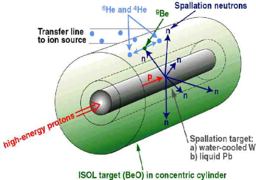
ISOL Target and Ion Source: The target system is patterned after that of the EURISOL facility H.L. Ravn et al. (2003). For 6He production, the target core would be a heavy metal (mercury H.L. Ravn (2003)) that converts the incoming proton beam into a neutron flux. Surrounding the core is a cylinder of BeO U. Köster et al. (2003) that produces 6He via the 9Be(n,) reaction. 18Ne would be produced via direct proton spallation on a MgO target H.L. Ravn et al. (1997). The nuclides of interest will be extracted from the target as neutral species, and so must be ionized to produce the beam to be accelerated. The proposed ion source technology, shown in Fig. 5, is based on a pulsed “ECR-duoplasmatron.”
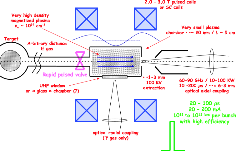
Figure 5: (Color) Proposed ion source system for production of 6He beam. -
•
Acceleration: Low energy acceleration would make use of a linac to accelerate the nuclide of interest to 20–100 MeV/u, followed by a Rapid Cycling Synchrotron (RCS) with multi-turn injection that would accelerate the ion beam to 300 MeV/u. This system would feed the CERN PS with 16 bunches (2.5 1012 ions per bunch), which would be merged to 8 bunches during the acceleration cycle to . Finally, the bunches would be transferred to the SPS and accelerated to , which corresponds to the maximum magnetic rigidity of that accelerator.
-
•
Decay Ring: The racetrack decay ring would have the same circumference as the SPS (6880 m), with a long straight section, some 2500 m, aimed at the detector. At the final energy, the lifetime of the beam becomes minutes rather than seconds. Stacking is required to load the ring with enough ions to get an acceptable neutrino flux.
The parallels with the Neutrino Factory are obvious. The main difference between the two types of facility is in the initial capture and beam preparation. In the Neutrino Factory, the beam must be bunched, phase rotated, and ionization cooled. In the Beta Beam facility, the beam must be collected, ionized, and bunched.
II.2.1 Proton Driver
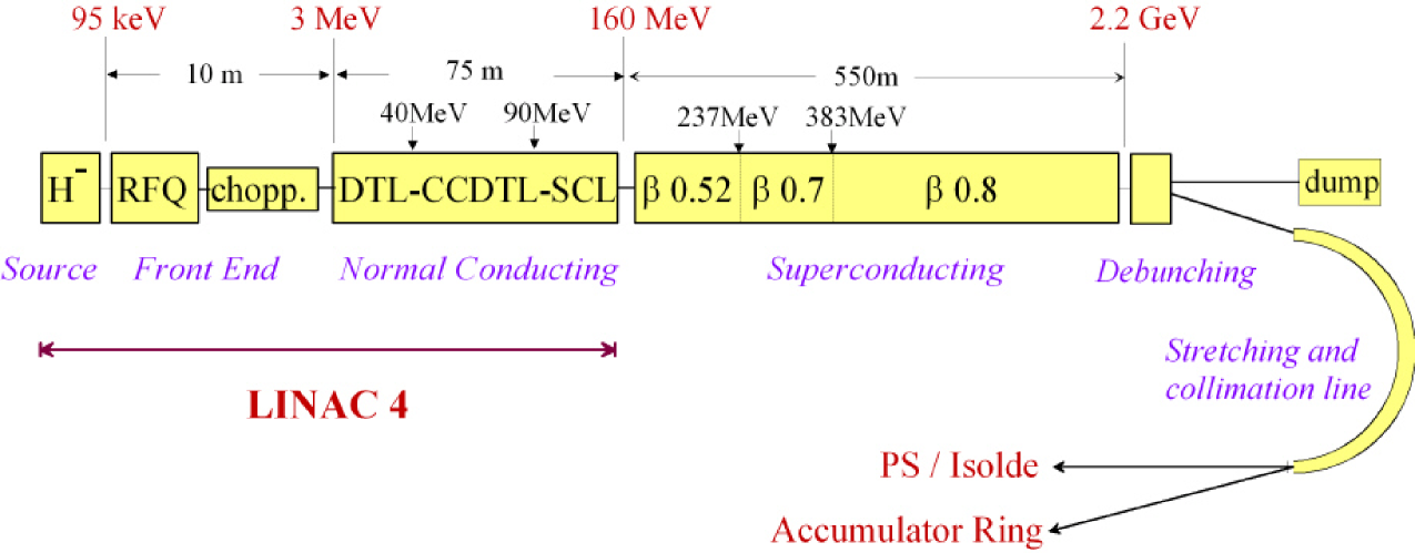
The proposed proton driver for the Beta Beam facility is the SPL, a 2.2 GeV Superconducting Proton Linac E. Métral, et al. presently being designed at CERN to serve both the LHC and the EURISOL facility. The machine will operate at 50 Hz and will be designed to provide up to 4 MW of proton beam power. The present scenario is illustrated in Fig. 6. It is anticipated that the ISOL target will require only about 5% of the proton beam power, i.e., about 200 kW.
II.2.2 ISOL Target and Ion Source
As noted earlier, the target for 6He will use a water-cooled tungsten or a liquid-lead core to serve as a proton-to-neutron converter. Surrounding this core will be a cylinder of BeO, as shown in Fig. 7. In the case of 18Ne, a more straightforward approach will suffice. The proton beam will impinge directly on a MgO target, producing the required nuclide via spallation. An ion source capable of producing the required intense pulses is proposed; development work on this device (see Fig. 5) is under way at Grenoble sor . The device uses a very high density plasma ( cm-3) in a 2–3 T solenoidal field and operates at 60–90 GHz. It is expected to provide pulses of 1012–1013 ions per bunch.
II.2.3 Acceleration
The proposed acceleration scheme is based on the existing CERN machines (PS and SPS). Initial acceleration would be via a linac, followed by a rapid cycling synchrotron that would be filled by multiturn injection. The RCS would provide a single bunch, 150 ns long, at 300 MeV/u. The PS is a relatively slow machine, and this results in substantial radiation levels due to decays while the beam energy, and hence the lifetime, is low. A rapid-cycling PS replacement would be of considerable benefit in this regard, though it is not part of the baseline scenario. Another idea that merit consideration is the use of a FFAG, which perhaps could be used to accelerate muons at a latter time.
The SPS space-charge limit at injection is another issue to deal with, and will likely require a transverse emittance blowup to manage it. A new 40 MHz rf system will be added to the existing 200 MHz system in the SPS to accelerate the beam to
II.2.4 Decay Ring
The beam is transferred at full energy to a racetrack-shaped Decay Ring having the same circumference as the SPS. The length of the decay straight section (the one aimed at the detector) is chosen to permit about 35% of the decays to occur there. At full energy, the lifetime is minutes rather than seconds. This allows—and also requires—the beam to be stacked in the Decay Ring to provide the required decay intensity. The proposed stacking technique, asymmetric bunch merging, is based on somewhat complicated rf gymnastics, but has already been shown to work experimentally in tests Bun . An interesting possibility that has arisen only recently is the idea of storing both 6He and 18Ne in the ring simultaneously. This requires that the neon beam have the same rigidity as the helium beam, which corresponds to For a detector at Fréjus, the optimum energies M. Mezzetto (2003) are and
III Beam properties
The most important neutrino oscillation physics questions that we wish to address in the coming decades require the study of transitions in long baseline experiments. Conventional neutrino beams are almost pure beams, which therefore permit the study of oscillations. The experiments must look for CC interactions in a distant detector. Backgrounds that fake CC interactions, together with a small component in the initial beam, account for of the total interaction rate. This makes it difficult for experiments using conventional neutrino beams to probe very small oscillation amplitudes, below the range. This limitation motivates new types of neutrino facilities that provide beams, permitting the search for oscillations, and if the beam energy is above the CC interaction threshold, the search for oscillations. Neutrino Factory and Beta Beam facilities both provide (and ) beams, but with somewhat different beam properties. We will begin by describing Neutrino Factory beams, and then describe Beta Beam facility beams.
III.1 Neutrino Factory Beams
Neutrino Factory beams are produced from muons decaying in a storage ring with long straight sections. Consider an ensemble of polarized negatively-charged muons. When the muons decay they produce muon neutrinos with a distribution of energies and angles in the muon rest–frame described by Gaisser (1990):
| (2) |
where , is the angle between the neutrino momentum vector and the muon spin direction, and is the average muon polarization along the beam direction. The electron antineutrino distribution is given by:
| (3) |
and the corresponding distributions for and from decay are obtained by the replacement . Only neutrinos and antineutrinos emitted in the forward direction () are relevant to the neutrino flux for long-baseline experiments; in this limit and at high energies the maximum in the laboratory frame is given by , where and are the usual relativistic factors. The and distributions as a function of the laboratory frame variables are then given by:
| (4) |
and
| (5) |
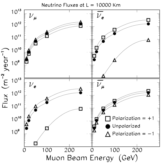
Thus, for a high energy muon beam with no beam divergence, the neutrino and antineutrino energy and angular distributions depend upon the parent muon energy, the decay angle, and the direction of the muon spin vector. With the muon beam intensities that could be provided by a muon–collider type muon source M. M. Alsharo´a et al. (2003) the resulting neutrino fluxes at a distant site would be large. For example, Fig. 8 shows as a function of muon energy and polarization, the computed fluxes per muon decays at a site on the other side of the Earth ( km). Note that the () fluxes are suppressed when the muons have This can be understood by examining Eq. (5) and noting that for the two terms cancel in the forward direction for all .
At low energies, the neutrino CC interaction cross section is dominated by quasi-elastic scattering and resonance production. However, if is greater than GeV, the total cross section is dominated by deep inelastic scattering and is approximately D. MacFarlane et al. (1984) (CCFR):
| (6) | |||||
| (7) |
The number of and CC events per incident neutrino observed in an isoscalar target is given by:
| (8) | |||||
| (9) |
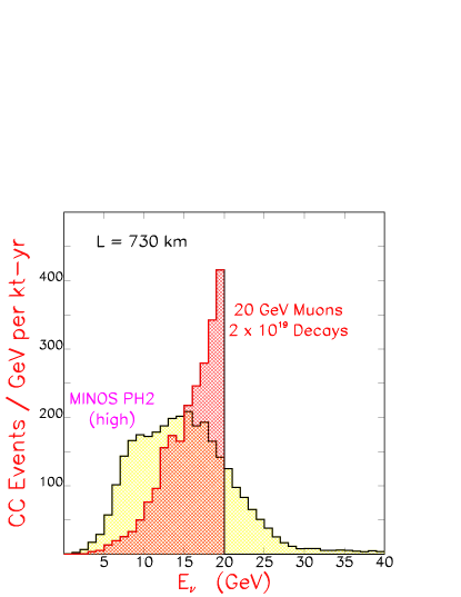
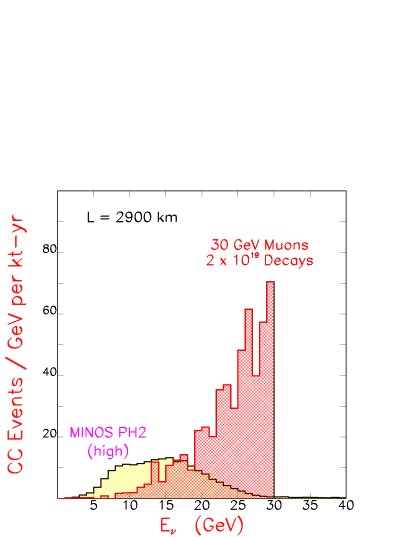
Using this simple form for the energy dependence of the cross section, the predicted energy distributions for and interacting in a far detector at a Neutrino Factory are shown in Fig. 9. The interacting energy distribution is compared in Fig. 10 with the corresponding distribution arising from the high–energy NUMI num wide-band beam. Note that neutrino beams from a Neutrino Factory have no high energy tail, and in that sense can be considered narrow-band beams.
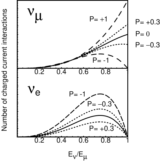

In practice, CC interactions can only be cleanly identified when the final state lepton exceeds a threshold energy. The calculated final state lepton distributions are shown in Fig. 11. Integrating over the energy distribution, the total and interaction rates per muon decay are given by:
| (10) |
and
| (11) |
where
| (12) |
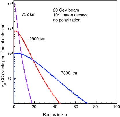
The calculated and CC interaction rates resulting from muon decays in the storage ring straight section of a Neutrino Factory are compared in Table 4 with expectations for the corresponding rates at the next generation of accelerator–based neutrino experiments. Note that event rates at a Neutrino Factory increase as , and are significantly larger than expected for the next generation of approved experiments if GeV. The radial dependence of the event rate is shown in Fig. 12 for a 20 GeV Neutrino Factory and three baselines.
| Experiment | Baseline | N( CC) | N( CC) | |||
|---|---|---|---|---|---|---|
| (km) | (GeV) | (GeV) | (per kton–yr) | (per kton–yr) | ||
| MINOS | Low energy | 732 | 3 | – | 458 | 1.3 |
| Medium energy | 732 | 6 | – | 1439 | 0.9 | |
| High energy | 732 | 12 | – | 3207 | 0.9 | |
| Muon ring | (GeV) | |||||
| 10 | 732 | 7.5 | 6.6 | 1400 | 620 | |
| 20 | 732 | 15 | 13 | 12000 | 5000 | |
| 50 | 732 | 38 | 33 | 1.8105 | 7.7104 | |
| Muon ring | (GeV) | |||||
| 10 | 2900 | 7.6 | 6.5 | 91 | 41 | |
| 20 | 2900 | 15 | 13 | 740 | 330 | |
| 50 | 2900 | 38 | 33 | 11000 | 4900 | |
| Muon ring | (GeV) | |||||
| 10 | 7300 | 7.5 | 6.4 | 14 | 6 | |
| 20 | 7300 | 15 | 13 | 110 | 51 | |
| 50 | 7300 | 38 | 33 | 1900 | 770 |
| Muon Beam | Beam | Rate | Target |
|---|---|---|---|
| property | Type | Dependence | Precision |
| Energy () | (no osc.) | ||
| Direction () | (no osc.) | ||
| (for ) | |||
| Divergence () | (no osc.) | ||
| (for ) | (for ) | ||
| Momentum spread () | (no osc.) | ||
| Polarization () | (no osc.) | ||
| (no osc.) |
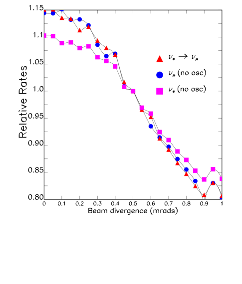
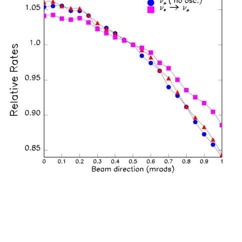
We next consider the systematic uncertainties on the neutrino flux. Since muon decay kinematics is very well understood, and the beam properties of the muons in the storage ring can be well determined, we expect the systematic uncertainties on the neutrino beam intensity and spectrum to be small compared to the corresponding uncertainties on the properties of conventional neutrino beams. In the muon decay straight section of a Neutrino Factory, the muon beam is designed to have an average divergence given by The neutrino beam divergence will therefore be dominated by muon decay kinematics, and uncertainties on the beam direction and divergence will yield only small uncertainties in the neutrino flux at a far site. However, if precise knowledge of the flux is required, the uncertainties on and must be taken into account, along with uncertainties on the flux arising from uncertainties on the muon energy distribution and polarization. The relationships between the uncertainties on the muon beam properties and the resulting uncertainties on the neutrino flux are summarized in Table 5. If, for example, we wish to know the and fluxes at a far site with a precision of 1%, we must determine the beam divergence, , to 20% (see, Fig. 13), and ensure that the beam direction is within of the nominal direction C. Crisan and S. Geer (2000) (see, Fig. 14). We point out that it should be possible to do much better than this, and consequently, to know the fluxes at the far site with a precision much better than 1%.
We now consider the event distributions in a detector at a near site, close to the Neutrino Factory, which will be quite different from the corresponding distributions at a far site. There are two main reasons for this difference. First, the near detector accepts neutrinos over a large range of muon decay angles , not just those neutrinos traveling in the extreme forward direction. This results in a broader neutrino energy distribution that is sensitive to the radial size of the detector (Fig. 15).
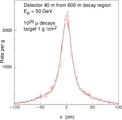
Second, if the distance of the near detector from the end of the decay straight section is of the order of the straight section length, then the acceptance of the detector varies with the position of the muon decay along the straight section. This results in a more complicated radial flux distribution than expected for a far detector. However, since the dominant effects are decay length and muon decay kinematics, it should be modeled quite accurately (Fig. 16).
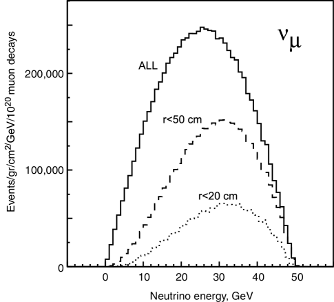
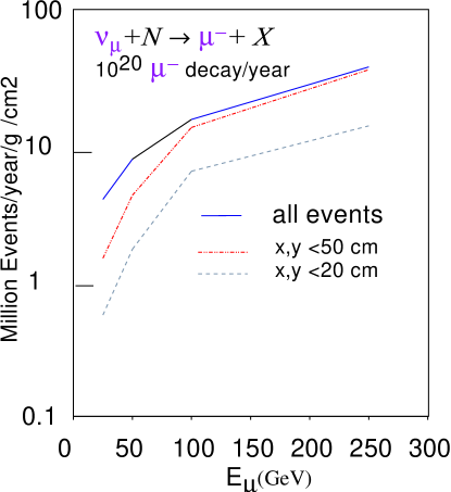
Note that, even in a limited angular range, the event rates in a near detector are very high. Figure 17 illustrates the event rates per g/cm2 as a function of energy. Because most of the neutrinos produced forward in the center of mass traverse the detector fiducial volume, the factor of present in the flux for is canceled and the event rate increases linearly with . For a 50 GeV muon storage ring, the interaction rate per 1020 muon decays is Finally, in the absence of special magnetized shielding, the high neutrino event rates in any material upstream of the detector will cause substantial backgrounds. The event rate in the last three interaction lengths () of the shielding between the detector and the storage ring would be 30 interactions per beam spill at a 15 Hz machine delivering muon decays per year. These high background rates will require clever magnetized shielding designs and fast detector readout to avoid overly high accidental rates in low mass experiments.
III.2 Beta Beams
We now consider the beam properties at a Beta Beam facility. In a Beta Beam facility the neutrinos are generated by the decay of radioactive nuclei rather than muons. The two ions deemed optimal are 18Ne for and 6He for production. The resulting initial neutrino beam consists of a single flavor. In addition, since the decay kinematics is well known, the uncertainties on the neutrino energy spectrum are expected to be small. The electron energy spectrum produced by a nuclear -decay at rest is
| (13) |
where is the electron end-point energy, which is 3.5 MeV for 6He and 3.4 MeV for 18Ne. In the rest frame of the ion, the spectrum of the neutrinos J. Burguet-Castell, D. Casper, J.J. Gomez-Cadenas, P. Hernandez, F. Sanchez (2004) is
| (14) |
After performing a boost and normalizing to the total decays (in the straight section) , the neutrino flux per solid angle in a detector located at a distance and aligned with the straight section can be calculated as
| (15) |
where , and
| (16) |
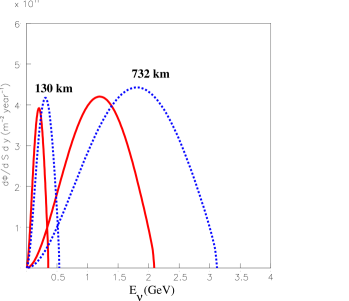
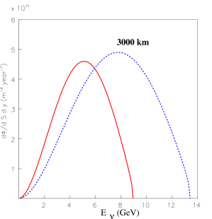
The neutrino flux and energy distribution depend upon the boost , and hence upon the energies of the stored radioactive ions. The original Beta Beam proposal B. Autin et al. (2003) was to use the CERN SPS to accelerate the ions. The desire to simultaneously store ions of both species in the storage ring, and build a large detector in the Fréjus tunnel in France (which fixes the baseline), has led to proposed Beta Beam energies corresponding to and 100 for the two ion species, yielding mean neutrino energies of 0.2 GeV and 0.3 GeV. Recently it has been suggested that these energies are too low for optimal sensitivity to the interesting physics, and hence higher energy scenarios are being considered, using the Fermilab Tevatron, or the CERN LHC to accelerate the ions. Figure 18 shows the expected fluxes for the three scenarios, “low” energy (e.g., SPS), “medium” energy (e.g., Tevatron), and “high” energy (e.g., LHC). Although the integrated fluxes are similar, the cross section grows with energy, yielding more events for the higher energies. Table 6 shows the expected charged current event rates for the three setups.
| L (km) | CC | CC | (GeV) | |
|---|---|---|---|---|
| 60/100 | 130 | 1.9 | 25.7 | 0.2/0.3 |
| 350/580 | 730 | 48.6 | 194.2 | 1.17/1.87 |
| 1500/2500 | 3000 | 244.5 | 800.2 | 5.01/7.55 |
However, it should be noted that the higher energy options require both a TeV (or multi-TeV) accelerator and storage ring, which are expensive and introduce additional technical challenges. Finally, further study is needed to fully explore the systematic uncertainties on the beam properties of a Beta Beam facility. Note however, that the neutrino beam divergence is controlled by the Q value of the beta decay, and the beam divergence in the straight section. In the CERN (low energy) case, the typical decay angle is 7 mrad. By contrast, the parent beam divergence would be O(100) rad, assuming a 200 m beta function in the decay section. For higher energies, both inherent neutrino divergence, and the parent beam divergence scale like 1/. Hence the decay kinematics is expected to dominate the beam divergence for all the Beta Beam scenarios. A more detailed understanding of the systematics must await a detailed design for the storage ring and an understanding of the beam halo, etc. Background conditions for near detectors also deserve study.
IV Neutrino Oscillation Physics Reach of a Neutrino Factory and Beta Beam
Ultimately, to fully test the three-flavor mixing framework, determine all of the relevant neutrino oscillation parameters, and answer the most important neutrino-oscillation related physics questions, we would like to measure the oscillation probabilities as a function of the baseline and neutrino energy (and hence ) for all possible initial and final flavors and . This requires a beam with a well known initial flavor content, and a detector that can identify the flavor of the interacting neutrino. The neutrinos interact in the detector via charged current (CC) and neutral current (NC) interactions to produce a lepton accompanied by a hadronic shower arising from the remnants of the struck nucleon. In CC interactions, the final-state lepton tags the flavor () of the interacting neutrino. To accomplish our ultimate goal, we will need in addition to beams, and detectors that can distinguish between NC, CC, CC, and CC interactions. Conventional neutrino beams are beams, Beta Beams provide beams, and Neutrino Factories provide and beams. The sensitivities of experiments at the different facilities will depend on their statistical precision, the background rates, the ability of the experiments to discriminate between true and false solutions within the three-flavor mixing parameter space, and the ability of the experimental setups to detect as many of the oscillation modes as possible. In the following, we will first consider the experimental signatures and sensitivities at a Neutrino Factory, and then the corresponding signatures and sensitivities at a Beta Beam facility.
IV.1 Neutrino Factory Sensitivity
IV.1.1 Wrong-Sign Muons
At a Neutrino Factory in which, for example, positive muons are stored, the initial beam consists of 50% and 50% . In the absence of oscillations, the CC interactions produce electrons and the CC interactions produce positive muons. Note that the charge of the final state lepton tags the flavor of the initial neutrino or antineutrino. In the presence of oscillations, the CC interactions produce negative muons (i.e., wrong–sign muons). This is a very clean experimental signature since, with a segmented magnetized iron-scintillator sampling calorimeter for example, it is straightforward to suppress backgrounds to 1 part in of the total CC interaction rate, or better. This means that at a Neutrino Factory backgrounds to the oscillation signal are extremely small. The full statistical sensitivity can therefore be exploited down to values of approaching before backgrounds must be subtracted and further advances in sensitivity scale like rather than . This enables Neutrino Factories to go beyond the sensitivities achievable by conventional neutrino Superbeams, by about two orders of magnitude. A more complete discussion of backgrounds at a Neutrino Factory can be found in Refs. C. Albright, et al. (2000); A. De Rujula, M. B. Gavela and P. Hernandez (1999); A. Cervera, A. Donini, M. B. Gavela, J. J. Gomez Cadenas, P. Hernandez, O. Mena and S. Rigolin (2000); M. Apollonio et al. (2002) (CERN working group on oscillation physics at the Neutrino Factory).

We now consider how wrong-sign muon measurements at a Neutrino Factory are used to answer the most important neutrino oscillation physics questions. Suppose we store positive muons in the Neutrino Factory, and measure the number of events tagged by a negative muon in a distant detector, and then store negative muons and measure the rate of events tagged by a positive muon. To illustrate the dependence of the expected measured rates on the chosen baseline, the neutrino mass hierarchy, and the complex phase , we will fix the other oscillation parameters and consider an experiment downstream of a 20 GeV Neutrino Factory. Let half of the data taking be with stored, and the other half with stored. In Fig. 19, the predicted ratio of wrong-sign muon events is shown as a function of baseline for eV2 and eV2, with set to the small value 0.004. (Although these values are now a little different from those emerging from global analyses of the atmospheric and solar neutrino data, they are the ones used for the figure, which comes from Ref. Geer (2002), and are still useful to illustrate how the measurements can be used to determine the oscillation parameters.) Figure 19 shows two bands. The upper (lower) band corresponds to Within the bands, the CP phase is varying. At short baselines the bands converge, and the ratio since the antineutrino CC cross section is half of the neutrino CC cross section. At large distances, matter effects enhance if and reduce if and the bands diverge. Matter effects become significant for baselines exceeding about 2000 km. The error bars indicate the expected statistical uncertainty on the measured with a data sample of kton-decays. With these statistics, the sign of is determined with very high statistical significance. With an order of magnitude smaller data sample (entry level scenario V. Barger, S. Geer, R. Raja, and K. Whisnant (2000a)) or with an order of magnitude smaller the statistical uncertainties would be larger, but the sign of could still be determined with convincing precision.
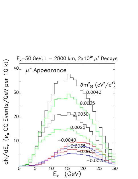
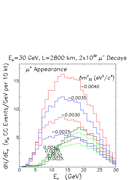
In addition to the ratio of wrong–sign muon signal rates , the two energy-dependent wrong-sign muon event energy distributions can be separately measured. To show how this additional information can help, the predicted measured energy distributions 2800 km downstream of a 30 GeV Neutrino Factory are shown in Figs. 20 and 21 for, respectively, and wrong–sign muon events. The distributions are shown for a range of positive and negative values of . Note that, after allowing for the factor of two difference between the neutrino and antineutrino cross sections, for a given , if we would expect to observe a lower wrong–sign muon event rate and a harder associated spectrum when positive muons are stored in the Neutrino Factory than when negative muons are stored. On the other hand, if we would expect to observe a higher wrong–sign muon event rate and a softer associated spectrum when positive muons are stored in the Neutrino Factory than when negative muons are stored. Hence, measuring the differential spectra when positive and negative muons are alternately stored in the Neutrino Factory can both enable the sign of to be unambiguously determined V. Barger, S. Geer, R. Raja, and K. Whisnant (2000b), and also provide a measurement of and a consistency check between the behavior of the rates and energy distributions.
IV.1.2 Other Channels
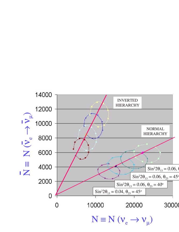
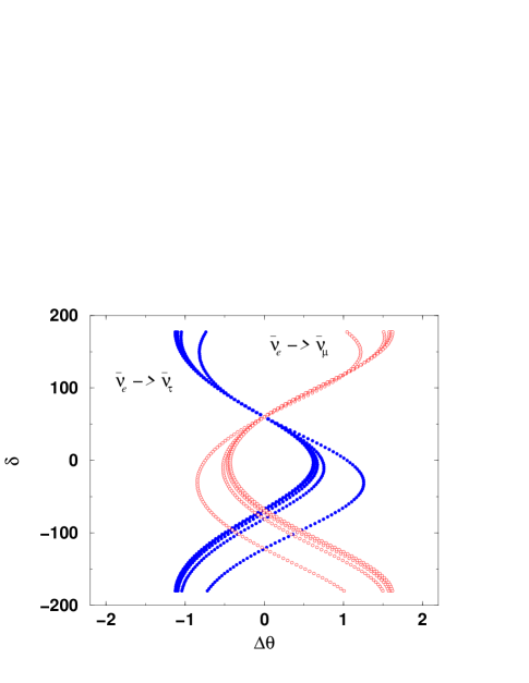
In practice, to measure , determine the mass hierarchy, and search for CP violation, the analysis of the wrong-sign muon rates must be performed allowing all of the oscillation parameters to simultaneously vary within their uncertainties. Since the relationship between the measured quantities and the underlying mixing parameters is complicated, with a minimal set of measurements it may not be possible to identify a unique region of parameter space consistent with the data. For Superbeams a detailed discussion of this problem can be found in Refs. H. Minakata and H. Nunokawa (2001); G. L. Fogli and E. Lisi (1996); W. Winter (2004); J. Burguet-Castell, M. B. Gavela, J. J. Gomez-Cadenas, P. Hernandez and O. Mena (2001); V. Barger, D. Marfatia and K. Whisnant (2002); J. Burguet-Castell, M. B. Gavela, J. J. Gomez-Cadenas, P. Hernandez and O. Mena (2002). To understand the nature of the challenge, Fig. 22 shows, as a function of and the assumed mass hierarchy, the predicted number of wrong–sign muon events when negative muons are stored in the Neutrino Factory, versus the corresponding rate when positive muons are stored. The example is for a 16 GeV Neutrino Factory with a baseline of 2000 km, and 10 years of data taking with a 100 kton detector and and decays in the beam-forming straight section per year. The ellipses show how the predicted rates vary as the CP phase varies. All of the CP conserving points ( and ) lie on the diagonal lines. Varying the mixing angles moves the ellipses up and down the lines. Varying the mass hierarchy moves the family of ellipses from one diagonal line to the other. Note that the statistics are large, and the statistical errors would be barely visible if plotted on this figure. Given these statistical errors, for the parameter region illustrated by the figure, determining the mass hierarchy (which diagonal line is the measured point closest to) will be straightforward. Determining whether there is CP violation in the lepton sector will amount to determining whether the measured point is consistent with being on the CP conserving line. Determining the exact values for the mixing angles and is more complicated, since various combinations can result in the same predicted values for the two measured rates. This is the origin of possible false solutions in the three–flavor mixing parameter space. To eliminate those false solutions, event samples other than transitions tagged by wrong-sign muons will be important. We have seen that, in the presence of oscillations, the CC interactions produce negative muons (i.e., wrong–sign muons). Similarly, oscillations produce wrong–sign electrons, oscillations produce events tagged by a and oscillations produce events tagged by a . Hence, there is a variety of information that can be used to measure or constrain neutrino oscillations at a Neutrino Factory, namely the rates and energy distributions of events tagged by
-
(a) right–sign muons
-
(b) wrong–sign muons
-
(c) electrons or positrons (their charge is difficult to determine in a massive detector)
-
(d) positive –leptons
-
(e) negative –leptons
-
(f) no charged lepton.
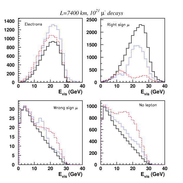
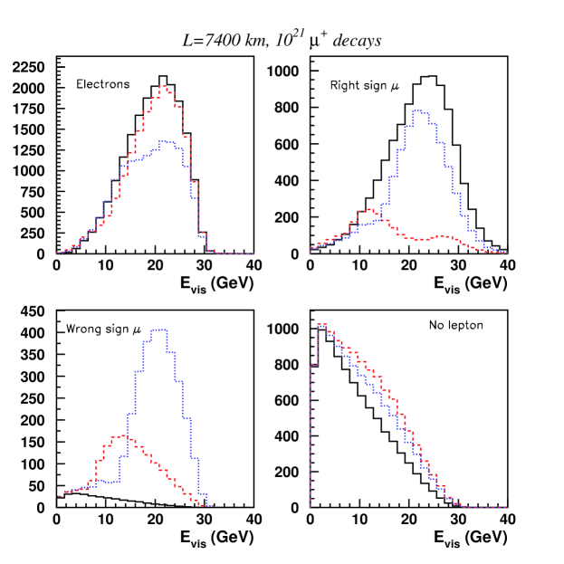
If these measurements are made when there are alternately positive and negative muons decaying in the storage ring, there are a total of 12 spectra that can be used to extract information about the oscillations. Some examples of the predicted measured spectra are shown as a function of the oscillation parameters in Figs. 23 and 24 for a 10 kton detector sited 7400 km downstream of a 30 GeV Neutrino Factory. These distributions are sensitive to the oscillation parameters, and can be fit simultaneously to extract the maximum information. Clearly, the high intensity , , , and beams at a Neutrino Factory would provide a wealth of precision oscillation data. The full value of this wealth of information has not been fully explored, but some specific things to be noted are:
-
1.
It has been shown A. Donini, D. Meloni and F. Migliozzi (2003); D. Autiero et al. (2004); P. Huber and W. Winter (2003); P. Huber, M. Lindner, and W. Winter (2002) that the various measurements at a Neutrino Factory provide sufficient information to eliminate false solutions within the three–flavor parameter space. Indeed the wealth of information in the Neutrino Factory data is essential for this purpose.
-
2.
If exceeds the channel is particularly important, both as a means to suppress the false solutions A. Donini, D. Meloni and F. Migliozzi (2003); D. Autiero et al. (2004); A. Donini, D. Meloni and P. Migliozzi (2002), and also as the only direct experimental probe of transitions. The ability of the measurements to eliminate false solutions is illustrated in Fig. 25, which, for a representative set of oscillation parameters, shows as a function of the CP phase the location of the false solution with respect to the correct solution in –space (or more precisely, the distance between the two solutions ). Note that, when compared to the case, has the opposite sign for . In practice, this means that together the two measurements enable the false solution to be effectively eliminated.
-
3.
Within the three–flavor framework, the relationship between the measured oscillation probabilities and the associated oscillation parameters is complicated. Experimental redundancy, permitting the over-determination of the oscillation parameters, is likely to prove essential, both to weed out misleading measurements and to ensure that the three-flavor framework is correct.
IV.1.3 Neutrino Factory Calculations
To understand how sensitive Neutrino Factory measurements will be in determining and the neutrino mass hierarchy, and the sensitivity to CP violation in the lepton sector, we must consider the impact of statistical and systematic uncertainties, correlations between the parameters that vary within fits to the measured distributions, and the presence or absence of false solutions in the three-flavor mixing parameter space. To take account of these effects, and to see which different neutrino oscillation experiments best complement one another, a global fitting program has been created P. Huber, M. Lindner, and W. Winter (2002); P. Huber, M. Lindner and W. Winter that uses simulated right-sign muon and wrong-sign muon data sets, and includes:
-
1.
Beam spectral and normalization uncertainties.
-
2.
Matter density variations of 5% about the average value.
-
3.
Constraint of solar neutrino oscillation parameters within the post-KamLAND LMA region.
-
4.
Simulation of CC QE, and CC inelastic, and NC events for all flavors. Note that the NC events are included in the analysis as a source of background. The NC signal is not yet exploited as an additional constraint.
-
5.
A check of the influence of cross section uncertainties (this mostly affects energies lower than those of interest for Neutrino Factories).
-
6.
Energy-dependent detection efficiencies, enabling energy threshold effects to be taken into account.
-
7.
Gaussian energy resolutions.
-
8.
Flavor, charge, and event misidentification.
-
9.
Overall energy-scale and normalization errors.
-
10.
An analysis of statistical and systematic precisions, and the ability to eliminate false solutions.
| -Beam | JHF-HK | Nu-Factory | |
| Signal | 4967 | 13171 | 69985 |
| Background | 397 | 2140 | 95.2 |
| Signal/Background | 12.5 | 6.2 | 735 |
| Signal | 477 | 9377 | 15342 |
| Background | 1 | 3326 | 180 |
| Signal/Background | 477.5 | 2.8 | 85.2 |
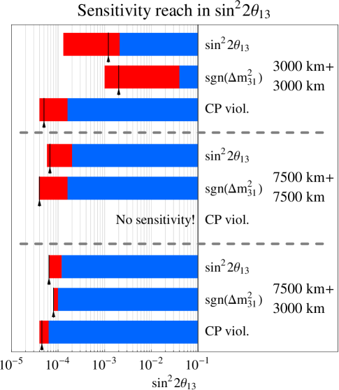
The calculated signal and background rates are listed in Table 7. The roughly two orders of magnitude improvement in the signal/background ratio at a Neutrino Factory, compared with the corresponding ratio at a high performance Superbeam, is evident. The results from the full calculations are shown in Fig. 26. The calculation is more fully described in Ref. P. Huber, M. Lindner, and W. Winter (2002). The figure shows the minimum value of for which three experimental goals could be achieved (with significance). First, the observation of a finite value of . Second, the determination of the neutrino mass hierarchy. Third, the observation of non-zero CP violation in the lepton sector if the underlying corresponds to maximal CP violation. The three groups of bars correspond to three different experimental scenarios, with different baselines. The favored scenario is the one illustrated by the bottom group of three bars, for which there are two detectors, one at km and the other at km. Note that:
At a Neutrino Factory can be measured, the neutrino mass hierarchy determined, and a search for CP violation in the lepton sector made for all values of down to O), or even a little less.
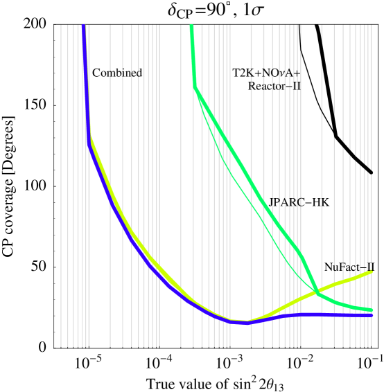
If is fairly large, Superbeam experiments may also establish its value, and perhaps determine the mass hierarchy and begin the search for CP violation. Figure 27 illustrates the role of a Neutrino Factory over a broad range of values. The figure shows, as a function of the underlying value of , the precision on the determination of the phase at a Neutrino Factory, and at a representative high-performance Superbeam, together with the combined Neutrino Factory plus Superbeam sensitivity. Below values of the Neutrino Factory sensitivity is significantly better than the sensitivity that can be achieved with Superbeams, and indeed provides the only sensitivity to the CP phase if is significantly smaller than . Above the Neutrino Factory measurements still enable a modest improvement to the CP violation measurement sensitivity, but the exact impact that a Neutrino Factory might have in this case is less clear. The uncertainty on the matter density, which is believed to be O is likely to be a limiting uncertainty for CP violation measurements T. Ohlsson and W. Winter (2003). Improved knowledge of the matter density along the neutrino flight-path would improve the expected Neutrino Factory sensitivity. In addition, Bueno et al. A. Bueno, M. Campanelli, A. Rubbia (2000) have shown that the energy dependencies of matter and CP violating effects are different, and can be exploited to further separate the two effects. For the case for a Neutrino Factory will depend upon just how well Superbeam experiments will ultimately be able to do, whether any new discoveries are made along the way that complicate the analysis, whether any theoretical progress is made along the way that leads to an emphasis on the type of measurements that a Neutrino Factory excels at, how important further tests of the oscillation formalism is in general, and the importance of observing and measuring oscillations in particular.
We conclude there is a strong physics case for a Neutrino Factory if is less than . There may also be a strong case if is larger than this, but it is too early to tell.
IV.1.4 Special Case:
The case is very special. The number of mixing angles needed to describe the unitary neutrino mixing matrix would be reduced from three to two, suggesting the existence of a new conservation law resulting in an additional constraint on the elements of the mixing matrix. The discovery of a new conservation law happens rarely in physics, and almost always leads to revolutionary insights in our understanding of how the physical universe works. Hence, if it were possible to establish that , it would be a major discovery. Note that in the limit the oscillation probability for transitions is finite, and is given by:
| (17) |
where the matter parameter if the neutrino energy corresponds to the matter resonance, which for a long-baseline terrestrial experiment means neutrino energies GeV. In addition, if the baseline is chosen such that corresponds to the oscillation maximum, then = 1, and we have that
| (18) |
Substituting into this expression values for the oscillation parameters that are consistent with the present solar and atmospheric neutrino data, we are led to conclude that even if , provided the neutrino energy and baseline are chosen appropriately, transitions are still directly observable in an appearance experiment if oscillation probabilities of O are observable. Hence, if is very small, the ideal neutrino oscillation experiment will be a long baseline experiment that uses neutrinos with energies close to 12 GeV, i.e., uses a baseline such that corresponds to the oscillation maximum, and is sensitive to values of or smaller. Neutrino Factories provide the only way we know to satisfy these experimental requirements.
If a Neutrino Factory experiment would enable (i) the first observation of transitions in an appearance experiment, and (ii) an upper limit on of O() or smaller.
These are major experimental results that would simultaneously provide a final confirmation the three-flavor mixing framework (by establishing transitions in an appearance experiment) while strongly suggesting the existence of a new conservation law. In considering the case it should be noted that within the framework of GUT theories, radiative corrections will change the value of measured in the laboratory from the underlying value of at the GUT scale. Recent calculations J.A. Aguilar-Saavedra, G.C. Branco, and F.R. Joaquim (2004) have suggested that these radiative corrections to will be O If this is the case, the ultimate Neutrino Factory experiment would not only provide the first direct observation of transitions, but would also
-
•
establish a finite value for at laboratory scales consistent with being zero at the GUT scale,
-
•
determine the sign of , and hence determine whether the neutrino mass hierarchy is normal or inverted, and
-
•
detect maximal CP violation in the lepton sector.
These would be tremendously important results.
IV.2 Beta Beam Calculations and Results
The Beta Beam concept is more recent than the Neutrino Factory idea, and the performance of Beta Beam experiments is less well established. Recent calculations of the sensitivity for low energy Beta Beam scenarios lin ; A. Donini, E. Fernandez-Martinez, P. Migliozzi, S. Rigolin and L. Scotto Lavina (2004) have included the effects of systematic uncertainties, correlations, and false solutions in parameter space. Expected signal and background rates are summarized in Table 7. The expected signal rates are relatively modest. The neutrino Beta Beam signal would be a factor of 2–3 less than expected at a high–performance Superbeam, and a factor of 14 less than at a Neutrino Factory. The rates are even lower for an antineutrino Beta Beam; a factor of 20 less than the rates at a high–performance Superbeam, and a factor of 32 less than at a Neutrino Factory. In addition, it has been pointed out J. Burguet-Castell, D. Casper, J.J. Gomez-Cadenas, P. Hernandez, F. Sanchez (2004) that the neutrino energies are comparable to the target nucleon kinetic energies due to Fermi motion, and therefore there is no useful spectral information in the low energy Beta Beam measurements. Hence, the useful information is restricted to the measured muon neutrino (and antineutrino) appearance rates. Nevertheless, the signal/background ratios are good: 12.5 for the neutrino Beta Beam (compared with 6.2 for the Superbeam and 735 for the Neutrino Factory), and an impressive 478 for the antineutrino Beta Beam (compared with 2.8 for the Superbeam and 85 for the Neutrino Factory). Hence the interest in Beta Beams.
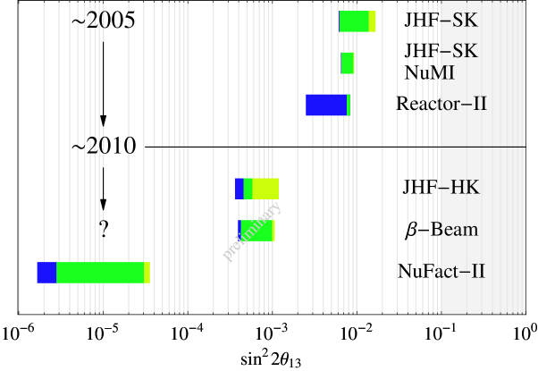
The ability of a low-energy Beta Beam to discover a finite value for is compared in Fig. 28 with the corresponding sensitivities at a Neutrino Factory and high performance Superbeam. The leftmost limits of each of the bars in Fig. 28 show the statistical sensitivities, and the shaded regions within the bars show the degradation of the sensitivities due to irreducible experimental systematics, the effects of correlations, and the effects of false solutions in the three-flavor mixing parameter space. The rightmost limit of the bars therefore gives the expected sensitivities for each experiment. The sensitivity of the low–energy Beta Beam experiment is expected to be comparable to the corresponding Superbeam sensitivity. A Neutrino Factory would improve on the Beta Beam sensitivity by about a factor of 40. Combining low-energy Beta Beam results (the two measured rates) with Superbeam results would enable the impact of correlations and ambiguities to be reduced, which would potentially enable an improvement in the sensitivity by a factor of 2–3 over the standalone results. Hence, low energy Beta Beams offer only a modest improvement in the sensitivity beyond that achievable with a high–performance Superbeam, and this realization has led to the consideration of higher energy Beta Beams J. Burguet-Castell, D. Casper, J.J. Gomez-Cadenas, P. Hernandez, F. Sanchez (2004); F. Terranova, A. Marotta, P. Migliozzi and M. Spinetti (2004). In particular, it has been proposed that the energies be increased by at least a factor of a few so that the neutrino and antineutrino energies are well above the Fermi motion region, which would enable useful spectral information to be extracted from the Beta Beam measurements. In addition, this would increase the signal rates (Table 6), and if the energy were sufficiently high to result in significant matter effects, then it would be possible (if is sufficiently large) to use Beta Beams to determine the neutrino mass hierarchy. The particular scenarios that have been considered J. Burguet-Castell, D. Casper, J.J. Gomez-Cadenas, P. Hernandez, F. Sanchez (2004) are:
-
Low Energy Beta Beam: This is the standard CERN scenario using the SPS for acceleration, and a 1 megaton water Cerenkov detector in the Fréjus tunnel (, L = 130 km).
-
Medium Energy Beta Beam: This would require the Fermilab Tevatron (or equivalent) for acceleration, and a 1 megaton water Cerenkov detector in the Soudan mine (, L = 730 km).
-
High Energy Beta Beam: This would require the LHC for acceleration, with , L = 3000 km.
In all three cases, the running time is assumed to be 10 years. The improvement in statistical precision enabled by the higher energy Beta Beam scenarios is illustrated in Table 6 and Fig. 29.
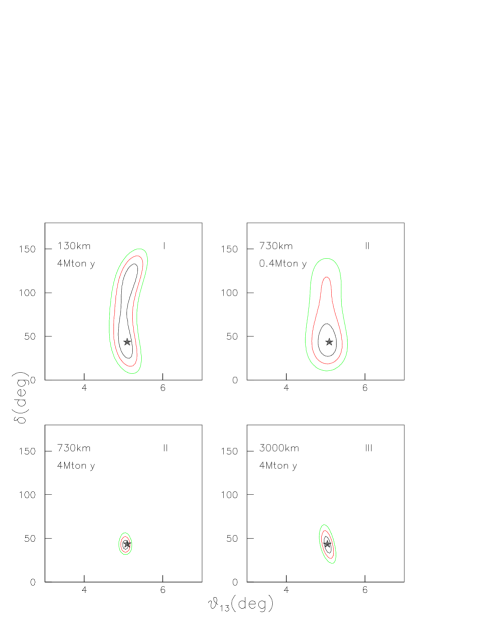
The figure shows, for the three scenarios, the 1, 2, and 3 contours in the ()–plane. Note that the expected sensitivity for the medium energy case with a “small” water Cerenkov detector is comparable to the low energy case with the megaton water Cerenkov detector. However, the medium energy sensitivity is dramatically improved with the much bigger detector. The further improvement obtained by going to LHC energies seems to be marginal. Given the likelihood that the LHC would not be available as a Beta Beam accelerator for a very long time, perhaps the most interesting scenario is the medium energy one. To understand the ability of medium energy Beta Beams to establish a finite value for , determine the neutrino mass hierarchy, and search for CP violation in the lepton sector, the full analysis must be performed, taking care of all known systematic effects, and the impact of correlations and degeneracies. Although this full analysis has not yet been done, a step towards it has been made, and the results are encouraging.

Figure 30 shows the region of the ()–plane within which (maximal CP violation) can be separated from (no CP violation) at the 99% C.L. The medium energy setup is sensitive to maximal CP violation for values of exceeding degrees (). This is within a factor of a few of the expected sensitivity that can be achieved at a Neutrino Factory. It will be interesting to see if this calculated medium energy Beta Beam sensitivity is significantly degraded when the uncertainties on all the oscillation parameters and the systematic uncertainties on the neutrino cross sections, etc., are included in the calculation.

Finally, Fig. 31 shows, for the medium energy Beta Beam scenario, the region of the ()–plane within which the neutrino mass hierarchy can be determined. The smallest value of for which this can be accomplished is seen to be degrees (), which is perhaps a little better than with a Superbeam, but is not competitive with a Neutrino Factory.
V Progress on Neutrino Factory and Beta Beam Facility Design
In this Section we describe the technical work accomplished as part of the present Study. For the Neutrino Factory (Sections V.1 and V.2) our focus was to update the FS2 design with some of the more cost-effective approaches we have studied. In particular, a more optimized capture section was designed, a shorter and less expensive bunching and phase rotation scheme was developed, and a more optimized acceleration scheme based on a combination of RLA and FFAG rings was worked out. Based on the improved designs presented here, we worked out approximately what the savings with respect to FS2 costs were. This is described in the Appendix.
For the Beta Beam facility, we have taken a brief look in Section V.3 at the implications of using existing U.S. accelerator facilities at BNL and Fermilab to provide the required beams. There is a real motivation to explore this idea, because it appears that there are significant scientific benefits associated with producing the neutrino beams from a Beta Beam facility at higher energy than would be possible at CERN in the foreseeable future.
V.1 Neutrino Factory Front End
The front end of the neutrino factory (the part of the facility between the target and the first linear accelerator) represented a large fraction of the total facility costs in FS2 S. Ozaki, R. Palmer, M. Zisman, and J. Gallardo, eds. (2001). However, several recent developments have given hope that a new design for the front end may be possible that is significantly less expensive:
- •
-
•
For a moderate cost, the transverse acceptance of the accelerator chain could be doubled from its FS2 value.
-
•
This diminished the demands on the transverse ionization cooling section and allowed the design of a simplified cooler with fewer components and reduced magnetic field strength.
We denote as “Study 2a” the simulations that have been made of the performance of this new front end, together with the new scheme for acceleration. The Monte Carlo simulations were performed with the code ICOOL Fernow (1999).
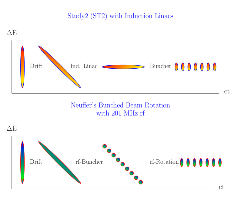
The concept of the adiabatic buncher is compared with the system used in FS2 in Fig. 32. The longitudinal phase space after the target is the same in both cases. Initially, there is a small spread in time, but a very large spread in energy. The target is followed by a drift space in both cases, where a strong correlation develops between time and energy. In FS2, the energy spread in the correlated beam was first flattened using a series of induction linacs. The induction linacs did an excellent job, reducing the final rms energy spread to 4.4%. The beam was then sent through a series of rf cavities for bunching, which increased the energy spread to In the new scheme, the correlated beam is first adiabatically bunched using a series of rf cavities with decreasing frequencies and increasing gradients. The beam is then phase rotated with a second string of rf cavities with decreasing frequencies and constant gradient. The final rms energy spread in the new design is 10.5%. This spread is adequate for the new cooling channel.
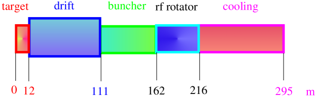
The overall layout of the new front–end design is shown in Fig. 33. The first 12 m is used to capture pions produced in the target. The field here drops adiabatically from 20 T over the target down to 1.75 T. At the same time, the radial aperture of the beam pipe increases from 7.5 cm at the target up to 25 cm. Next comes 100 m for the pions to decay into muons and for the energy-time correlation to develop. The adiabatic bunching occupies the next 50 m and the phase rotation 50 m following that. Lastly, the channel has 80 m of ionization cooling. The total length of the new front end is m.

The longitudinal field component on-axis is shown for the full front-end in Fig. 34. The field falls very rapidly in the collection region to a value of 1.75 T. It keeps this value with very little ripple over the decay, buncher and rotator regions. After a short matching section, the 1.75 T field is changed adiabatically to the alternating field used in the cooler. The beam distributions used in the simulations were generated using MARS Mokhov (2001). The distribution is calculated for a 24 GeV proton beam interacting with a Hg jet McDonald (2001). The jet is incident at an angle of 100 mrad to the solenoid axis, while the beam is incident at an angle of 67 mrad to the solenoid axis. An independent study showed that the resulting 33 mrad crossing angle gives near-peak acceptance for the produced pions. An examination of particles that were propagated to the end of the front-end channel shows that they have a peak initial longitudinal momentum of 300 MeV/c with a long high-energy tail, and a peak initial transverse momentum 180 MeV/c.
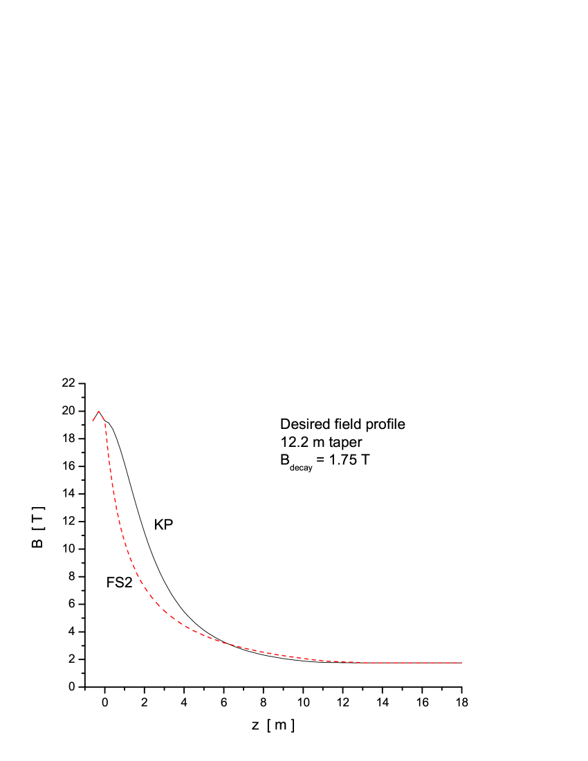
We used an improved axial field profile in the capture region that increased the final number of muons per proton in the accelerator acceptance by 10%. The new axial field profile (marked KP) is compared in Fig. 35 with the profile used in FS2. Figure 36 shows the actual coil configuration in the collection region. The end of the 60 cm long target region is defined as The three small radius coils near are Cu coils, while the others are superconducting. The left axis shows the error field on-axis compared with the desired field profile. We see that the peak error field is T.
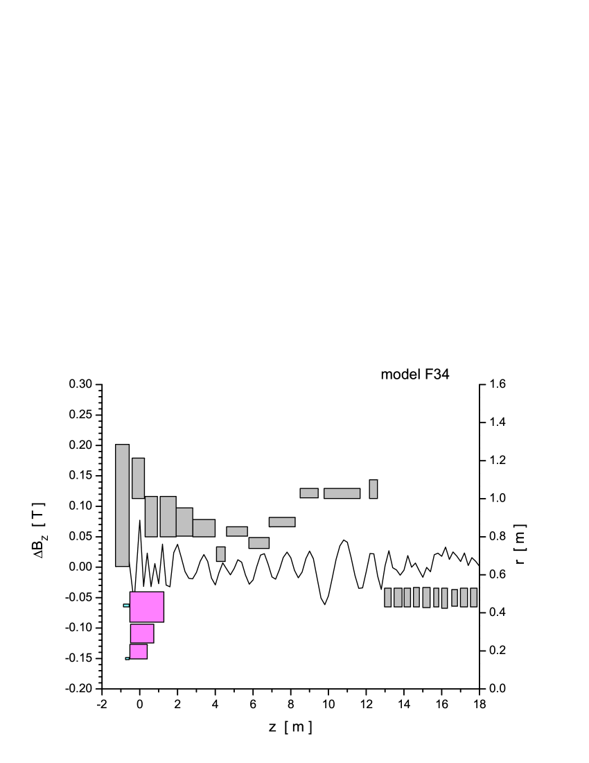
Figure 37 shows a MARS calculation of the absorbed radiation dose in the collection region. The peak deposition in the superconducting coils is Mgy/yr for a 1 MW beam running for 1 Snowmass year of s. Assuming a lifetime dose for the insulation of 100 Mgy, there should be no problem with radiation damage in the coils.
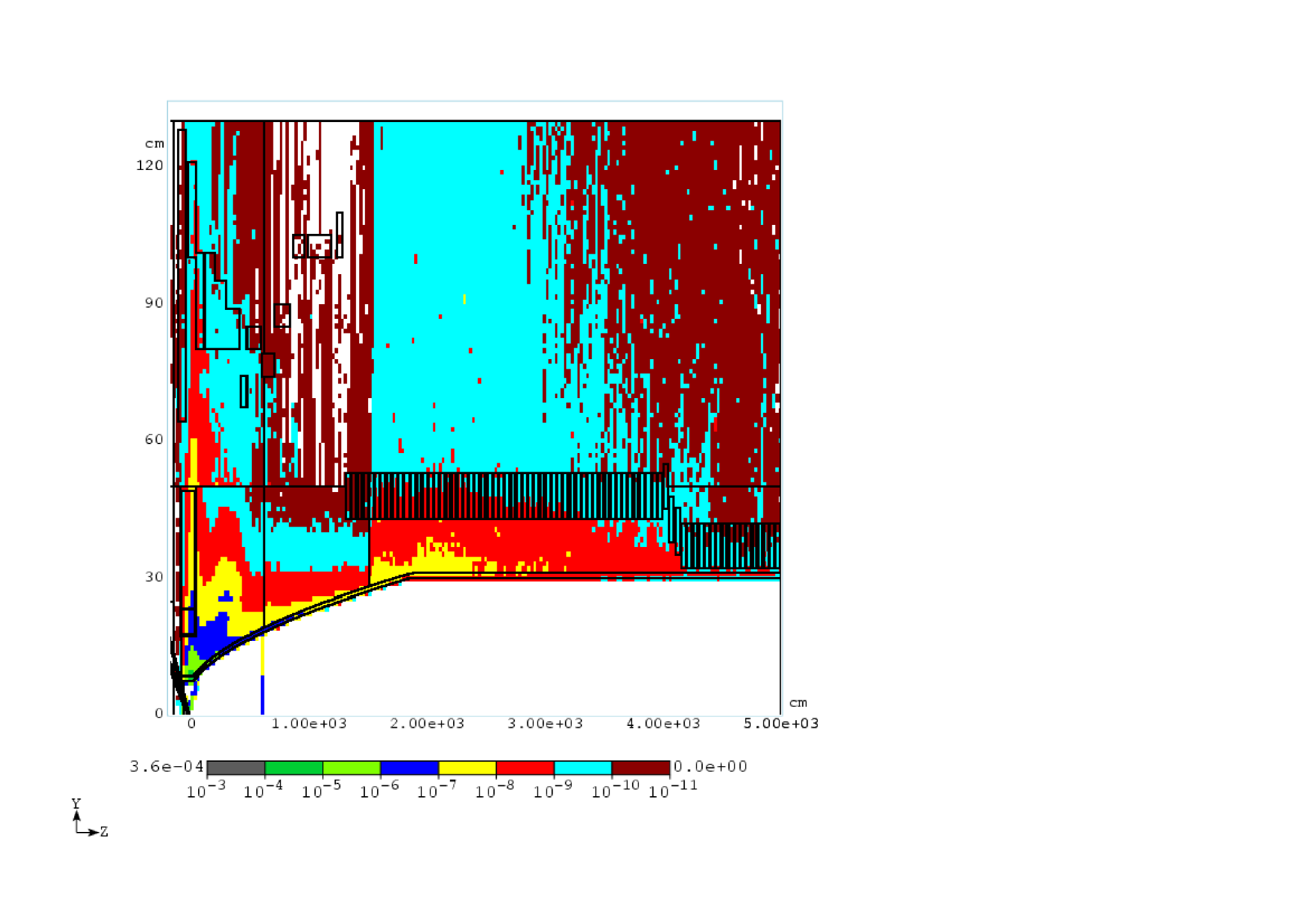
Two cells of the buncher lattice are shown schematically in Fig. 38. Most of the 75 cm cell length is occupied by the 50-cm-long rf cavity. The cavity iris is covered with a Be window. The limiting radial aperture in the cell is determined by the 25 cm radius of the window. The 50-cm-long solenoid was placed outside the rf cavity in order to decrease the magnetic field ripple on the axis and minimize beam losses from momentum stop bands. The buncher section contains 27 cavities with 13 discrete frequencies and gradients varying from 5–10 MV/m.
The frequencies decrease from 333 to 234 MHz in the buncher region. The cavities are not equally spaced. Fewer cavities are used at the beginning where the required gradients are small. Figure 39 shows the correlated longitudinal phase space and the bunching produced by the buncher.
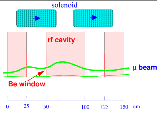
The rotator cell is very similar to the buncher cell. The major difference is the use of tapered Be windows on the cavities because of the higher rf gradient. There are 72 cavities in the rotator region, with 15 different frequencies. The frequencies decrease from 232 to 201 MHz in this part of the front end. All cavities have a gradient of 12.5 MV/m. The energy spread in the beam is significantly reduced.
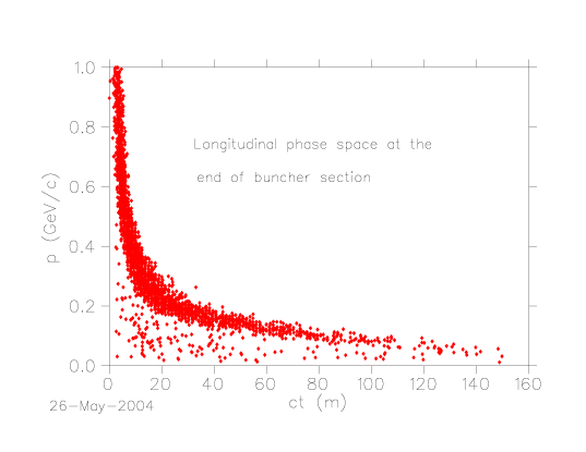
The cooling channel was designed to have a relatively flat transverse beta function with a magnitude of about 80 cm. One cell of the channel is shown in Fig. 40.
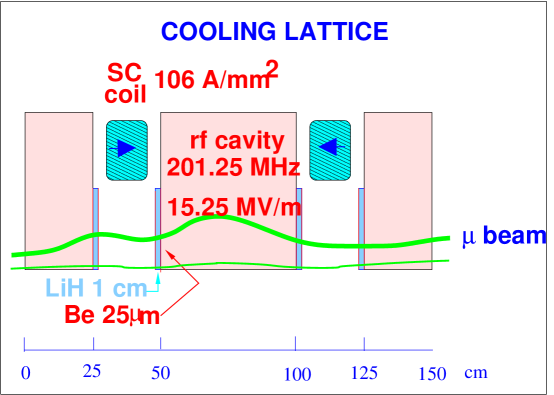
Most of the 150 cm cell length is taken up by the 50-cm-long rf cavities. The cavities have a frequency of 201.25 MHz and a gradient of 15.25 MV/m. A novel aspect of this design comes from using the windows on the rf cavity as the cooling absorbers. This is possible because the near constant function does not significantly increase the emittance heating at the window location. The window consists of a 1 cm thickness of LiH with m thick Be coatings (The Be will, in turn, have a thin coating of TiN to prevent multipactoring Chao and Tigner (1999).) The alternating 2.8 T solenoidal field is produced with one solenoid per half cell, located between the rf cavities. Figure 41 shows the longitudinal phase space at the end of the cooling section. The reduction in normalized transverse emittance along the cooling channel is shown in the left plot of Fig. 42 and the right plot shows the normalized longitudinal emittance.
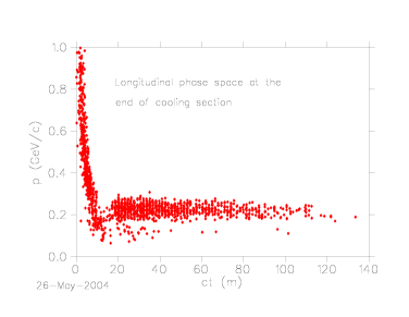
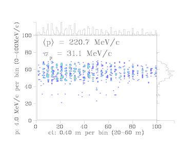
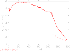
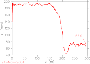
The channel produces a final value of mm rad, that is, more than a factor of two reduction from the initial value. The equilibrium value for a LiH absorber with an 80 cm function is about mm rad. Figure 43 shows the muons per proton that fit into the accelerator transverse normalized acceptance of mm rad and normalized longitudinal acceptance of mm. The 80-m-long cooling channel raises this quantity by about a factor of 1.7. The current best value is This is the same value obtained in FS2. Thus, we have achieved the identical performance at the entrance to the accelerator as FS2, but with a significantly simpler, shorter, and presumably less expensive channel design. In addition, unlike FS2, this channel transmits both signs of muons produced at the target. With appropriate modifications to the transport line going into the storage ring, this design could deliver both (time tagged) neutrinos and antineutrinos to the detector.
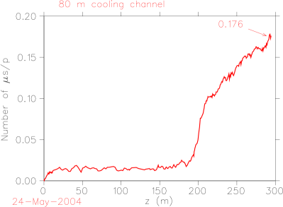
The beam at the end of the cooling section consists of a train of bunches (one sign) with a varying population of muons in each one; this is shown in Fig. 44.
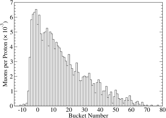
Figure 45 depicts the longitudinal phase space of one of the bunches and Fig. 46 shows a few interleaved and bunches exiting the cooling section.
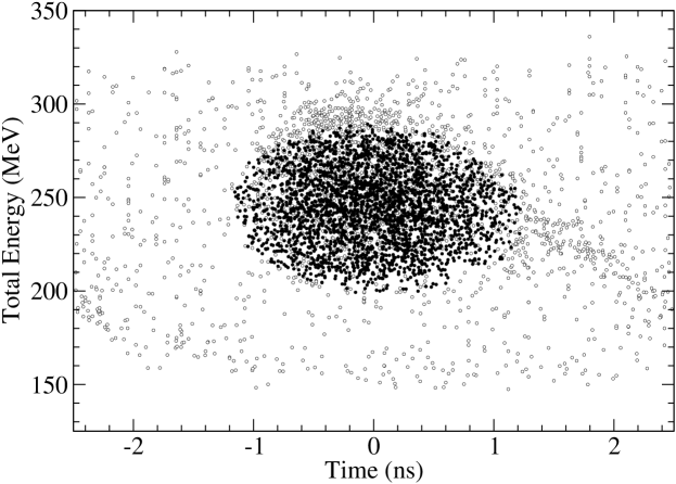
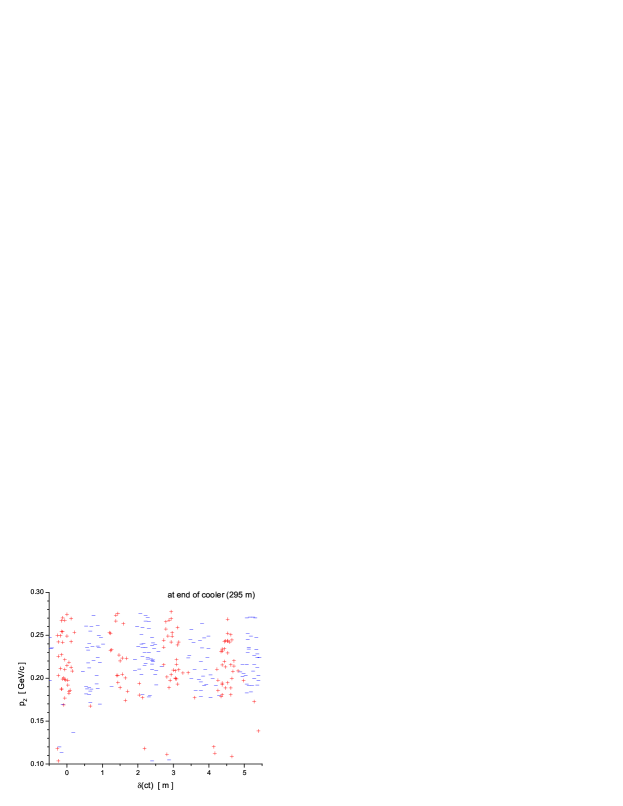
V.1.1 Other Variants
The present scenario is not completely optimized in either performance or cost. In this section we discuss some of the options that have already been studied briefly or that might be developed in future studies. Some variations we have considered:
-
•
Be absorbers in place of LiH absorbers
-
•
Shorter buncher rotator
-
•
Shorter bunch train
-
•
Different rf frequency
-
•
Gas-filled cavities
-
•
Quadrupole-based cooling channel
The configuration of LiH absorbers with Be windows could be simplified by substituting thicker Be windows as the end plates of the cavities, with a thickness chosen to make the total energy loss the same as that in the baseline foil + LiH absorber case. This would eliminate the need for thin Be windows. Cooling would be a bit less effective because of the greater multiple scattering in Be absorbers. An initial evaluation D. Neuffer (2004) of a Be-only scenario showed somewhat less capture into the acceleration channel acceptance (15%). A scenario in which Be absorbers are initially installed and then upgraded later to more efficient LiH absorbers is, of course, also possible.
The baseline scenario requires a roughly 110 m drift, a 51 m buncher and a 52 m high-voltage phase rotation section. These parameters have not been optimized. For comparison, we considered an example having only a 26 m phase rotation section D. Neuffer (2004). The shorter rotation section would be significantly less expensive since it is not only shorter but provides about 200 MV less of high-gradient rf voltage. Initial evaluations indicate only small decreases in captured muons (10%).
The baseline case generates and bunch trains that are about 100 m long. These bunch trains are matched to the FS2 scenario requirements; in particular, they fit within the circumferences of the FS2, and the presently envisioned, accelerators and storage ring. However, other scenarios might make use of smaller circumference ring coolers, accelerators, and storage rings, and thus require shorter bunch trains. For example, a scenario with a 20 m drift, 20 m buncher and 20 m phase rotator has been explored D. Neuffer (2004). This produces a roughly 20 m long bunch train.
Although this shorter system would be much less expensive than the present roughly 200 m long system, an initial evaluation showed that the total number of captured muons was substantially reduced (by about 50%). (On the other hand, a longer system, capturing longer bunch trains, might produce more muons, at a small incremental cost.)
Both FS2 and our present scenario use 201.25 MHz rf as the baseline final operating frequency, because of the availability of rf components at that frequency and because it is a plausible optimum for large-aperture and high-gradient operation. Other baseline frequencies could be considered, e.g., scenarios at 50, 100, 300 or 400 MHz. Lower frequencies (larger bunches) may be desirable if the accelerator longitudinal motion requires larger phase-space buckets.
Muons Inc. has an STTR grant to explore the use of hydrogen gas-filled rf cavities for muon cooling R. Johnson et al. (2003). This approach simplifies the cooling channel design by integrating the energy-loss material into the rf system. Moreover, it may be more effective in permitting high-gradient operation of the cavities. Such cavities could also be used in the cooling and phase-rotation (and possibly buncher) sections; an exploration with cost-performance optimization is planned.
The transport and cooling system in the front-end scenario considered here uses high-field solenoids for focusing. A cooling system with similar performance parameters using large-aperture quadrupoles has also been examined C. Johnstone et al. (2004), though a cost-performance comparison has not yet been made.
V.2 Neutrino Factory Acceleration
| Initial kinetic energy (MeV) | 187 |
| Final total energy (GeV) | 20 |
| Normalized transverse acceptance (mm) | 30 |
| Normalized longitudinal acceptance (mm) | 150 |
| Bunching frequency (MHz) | 201.25 |
| Maximum muons per bunch | |
| Muons per bunch train per sign | |
| Bunches in train | 89 |
| Average repetition rate (Hz) | 15 |
| Minimum time between pulses (ms) | 20 |
The acceleration system takes the beam from the end of the cooling channel and accelerates it to the energy required for the decay ring. Table 8 gives the design parameters of the acceleration system. Acceptance is defined such that if is the transverse acceptance and is the beta function, then the maximum particle displacement (of the particles we transmit) from the reference orbit is , where is the particle’s total momentum, is the particle’s rest mass, and is the speed of light. The acceleration system is able to accelerate bunch trains of both signs simultaneously.
To reduce costs, the RLA acceleration systems from FS2 will be replaced, as much as possible, by Fixed-Field Alternating Gradient (FFAG) accelerators.
V.2.1 Initial Parameter Sets
| Maximum energy gain per cavity (MeV) | 7.5 | |||
| Stored energy per cavity (J) | 368 | |||
| Cells without cavities | 8 | |||
| RF drift length (m) | 2 | |||
| Drift length between quadrupoles (m) | 0.5 | |||
| Initial total energy (GeV) | 5 | 10 | ||
| Final total energy (GeV) | 10 | 20 | ||
| Number of cells | 90 | 105 | ||
| Magnet type | Defocusing | Focusing | Defocusing | Focusing |
| Magnet length (m) | 1.612338 | 1.065600 | 1.762347 | 1.275747 |
| Reference orbit radius of curvature (m) | 15.2740 | -59.6174 | 18.4002 | -70.9958 |
| Magnet center offset from reference orbit (mm) | -1.573 | 7.667 | 1.148 | 8.745 |
| Magnet aperture radius (cm) | 14.0916 | 15.2628 | 10.3756 | 12.6256 |
| Field on reference orbit (T) | 1.63774 | -0.41959 | 2.71917 | -0.70474 |
| Field gradient (T/m) | -9.1883 | 8.1768 | -15.4948 | 12.5874 |
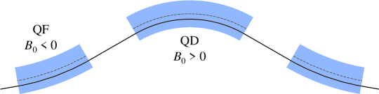
Based on an earlier version of the cost optimization process described below, it was decided that two factor-of-two FFAG stages would be used: one from 5 to 10 GeV, the other from 10 to 20 GeV total energy. Triplet lattices were chosen for their good longitudinal performance and the extensive study that had been done on them. The parameters that we adopted are given in Table 9.
The 201.25 MHz cavities were taken to be single-cell superconducting cavities. The energy gain per rf cavity was chosen based on the gradients already achieved in the cavity studied at Cornell, namely 10 MV/m at 4.2 K (they have achieved 11 MV/m at 2.5 K) R.L. Geng et al. (2003). This is a very conservative number, as there is every reason to believe that improved sputtering techniques will allow the cavity to achieve a gradient of 15 MV/m or higher. Energy gain and stored energy are computed by scaling from the values for the 300 mm aperture FS2 cavities S. Ozaki, R. Palmer, M. Zisman, and J. Gallardo, eds. (2001),R.L. Geng et al. (2003).
With the beam intensity given in Table 8, and both signs of muons, about 16% of the stored energy will be extracted from the cavities in the 5–10 GeV FFAG, and about 27% will be extracted in the 10–20 GeV. While this may seem substantial, it is easily handled. To keep the average voltage to 7.5 MV per cavity, one need only increase the initial voltage to 7.8 MV for the 5–10 GeV FFAG and 8.1 MV for the 10–20 GeV FFAG. The most important effect is a differential acceleration between the head and tail of the bunch train, which is about 1% for both cases. This may be at least partially correctable by a phase offset between the cavity and the bunch train.
V.2.2 Low Energy Acceleration
Based on cost considerations (see Section V.2) we have chosen not to use FFAGs below 5 GeV total energy. Therefore, we must provide alternative acceleration up to that point. As in FS2, we use a linac from the lowest energies to 1.5 GeV, followed by a recirculating linear accelerator (RLA).
The linac turns out to be strongly constrained by the transverse acceptance. In FS2, there were three types of cryomodules, containing one, two, and four cavities, respectively. With our larger acceptance, the cryomodules from FS2 would require the beam to have a momentum of at least 420 MeV/c, 672 MeV/c, and 1783 MeV/c, respectively. Note that the lowest momentum is much higher than the average momentum in the cooling channel, which is about 220 MeV/c. Thus, we need to make adjustments to the FS2 design to be able to accelerate this larger beam.
| Cryostat I | Cryostat II | Cryostat III | |||
|---|---|---|---|---|---|
| End to solenoid | 0.25 | To solenoid | 0.25 | To solenoid | 0.25 |
| Solenoid | 1.50 | Solenoid | 1.50 | Solenoid | 1.50 |
| Input coupler | 0.50 | Input coupler | 0.50 | Input coupler | 0.50 |
| Cavity | 0.75 | Cavity | 1.50 | Cavity | 1.50 |
| To end | 0.25 | Input coupler | 0.50 | Between cavities | 0.75 |
| Total | 3.25 | To end | 0.25 | Cavity | 1.50 |
| Total | 4.50 | Input coupler | 0.50 | ||
| To end | 0.25 | ||||
| Total | 6.75 | ||||
In particular, to increase the acceptance, we must reduce the lengths of the cryomodules. We first construct a very short cryomodule by using a single one-cell cavity instead of the two-cell cavities in the FS2 cryomodules. Not only does this shorten the cavity itself, it also eliminates one of the input couplers. Secondly, we remove 50 cm between the solenoid and the input coupler. We intend to run the cavities with up to 0.1 T on them M. Ono et al. (1999); this is acceptable provided the cavities are cooled down before the magnets are powered. The field profile of the solenoids shown in FS2 indicates that the iron shield on the solenoids is sufficient to bring the field down to that level even immediately adjacent to the solenoid shield. Finally, the FS2 cryomodules left 75 cm for the end of the cryostat; we have reduced this to 50 cm. Together, these changes permit a total length for the first module type of 3.25 m. Table 10 shows the dimensions of this cryostat. The two shortest cryostats from FS2 have been adjusted to meet these specifications and, in addition, for the “intermediate” cryostat the spacing between the cavities was reduced to 75 cm, under the assumptions that the cavities will be allowed to couple weakly, and that the entire module will be tuned appropriately to take this into account.
| Cryo I | Cryo II | Cryo III | |
| Length (m) | 3.25 | 4.50 | 6.75 |
| Minimum allowed momentum (MeV/c) | 273 | 378 | 567 |
| Number of modules | 18 | 12 | 23 |
| Cells per cavity | 1 | 2 | 2 |
| Cavities per module | 1 | 1 | 2 |
| Maximum energy gain per cavity (MeV) | 11.25 | 22.5 | 22.5 |
| RF Frequency (MHz) | 201.25 | 201.25 | 201.25 |
| Solenoid length (m) | 1 | 1 | 1 |
| Solenoid field (T) | 2.1 | 2.1 | 2.1 |
Table 11 summarizes parameters for the linac. The phase of the cavities in the linac will be varied linearly with length from about 65∘ at the beginning of the linac to 0∘ at the end. As indicated in Table 11, we must inject into the linac at a momentum of 273 MeV/c, which is still higher than the average momentum in the cooling channel. We deal with this by designing a matching section from the cooling channel to the linac in which sufficient acceleration will occur to reach the required momentum for the linac. That matching section will consist of cavities similar to those in the cooling channel, but with thinner windows.
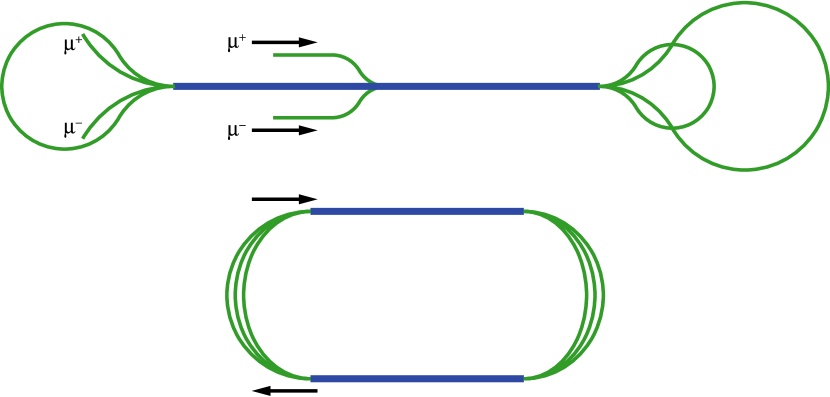
Compared to FS2, we are injecting into the RLA at a lower energy and are accelerating over a much smaller energy range. This will make it more difficult to have a large number of turns in the RLA. To mitigate this, we choose a “dogbone” layout for the RLA J.S. Berg, C. Johnstone, and D. Summers (2001). For a given amount of installed rf, the dogbone layout has twice the energy separation of the racetrack layout at the spreaders and recombiners, making the switchyard much easier and allowing more passes through the linac.
One disadvantage of the dogbone layout is that, because of the longer linac and the very low injection energy, there is a significant phase shift of the reference particle with respect to the cavity phases along the length of the linac in the first pass (or the last pass, depending on which energy the cavities are phased for). To reduce this effect, we inject into the center of the linac (as shown in Fig. 48).
In the dogbone RLA, we have just over 1 GeV of linac, and we make three and a half passes through that linac to accelerate from a total energy of 1.5 GeV to 5 GeV. The linac will use the same cryomodules that were used in the RLA in FS2.
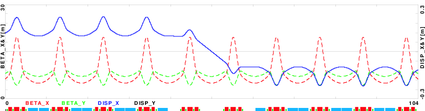
Since the dogbone arc changes its direction of bend twice in each arc, dispersion matching must be handled carefully. This is done by having a 90∘ phase advance per cell, and removing the dipoles from two consecutive cells. This will cause the dispersion to switch to the other sign as desired, as shown in Figure 49.
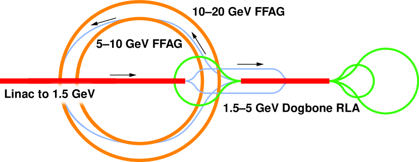
Figure 50 shows a compact potential layout for all the acceleration systems described here.
V.2.3 FFAG Tracking Results
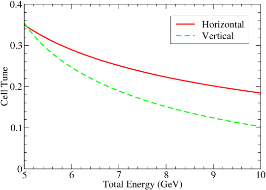
Initial experience with FFAG lattices having a linear midplane field profile has shown them to have a good dynamic aperture at fixed energies. We are careful to avoid single-cell linear resonances to prevent beam loss. However, since the tune is not constant (see Fig. 51), the single-cell tune will pass through many nonlinear resonances. Nonlinearities in the magnetic field due to end effects are capable of driving those nonlinear resonances, and we must be sure that there is no beam loss and minimal emittance growth because of this. Furthermore, there is the potential to weakly drive multi-cell linear resonances because the changing energy makes subsequent cells appear slightly different from each other. These effects can be studied through tracking.
ICOOL Fernow (1999) is used for tracking for several reasons. It will allow for a fairly arbitrary end-field description, it will attempt to make that description consistent with Maxwell’s equations, and it will track accurately when the lattice acceptances, beam sizes, and energy spread are all large.
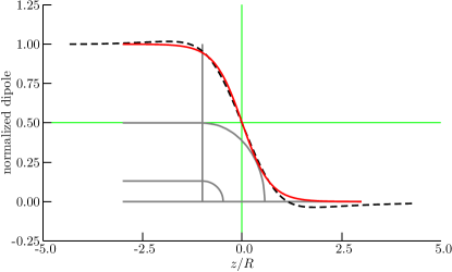
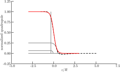
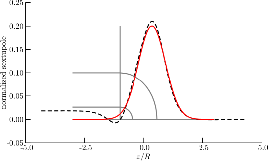
We begin by constructing a simple model of both a quadrupole and dipole -type magnet, without iron, using TOSCA ope . At the end of the magnet, the field does not immediately drop to zero, but falls gradually, as shown in Fig. 52. The end-field falloff in the dipole and quadrupole generates nonlinear fields, which ICOOL calculates. In addition, there are higher-order multipoles generated by breaking the magnet symmetry at the ends where the coils form closed loops. We use TOSCA to compute the sextupole components that arise from this effect, as shown in Fig. 53, and include them in our computation.
The TOSCA computation is done without iron, which leads to the overshoot in the field values in Figs. 52–53. Iron in the magnet will likely eliminate that overshoot. Thus, we approximate the fields from TOSCA using functions without the overshoot. Fitting roughly to the TOSCA results, the fields are approximated by
| (19) |
where is the magnet aperture radius, is the dipole field, is the dipole field in the center of the magnet, is the quadrupole field, is the quadrupole field in the center of the magnet, and is the maximum magnitude of the sextupole field at the radius . These fitted functions are shown in their corresponding plots in Figs. 52–53.
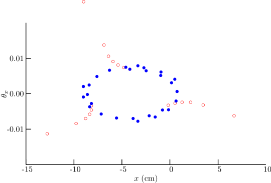
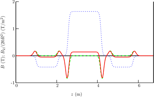
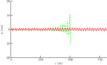
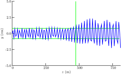
Injecting particles at the outer edge of the acceptance and tracking through several cells, indicated a large third-order resonance at around 5.1 GeV/c as shown in Fig. 54. This resonance is presumably being driven by the sextupole fields at the magnet ends. The strength of the resonance can be reduced if the integrated sextupole in the magnet is made zero. With some experimentation, it was found that if the integrated body sextupole was set to 68% of the integrated end sextupoles, (see Fig. 55), the resonance was eliminated (also shown in Fig. 54). When acceleration is included, one sees particle loss when accelerating through the resonance if there is no body sextupole correcting the end sextupoles, while there appears to be almost none with the body correction included (see Fig. 56). If the body correction is only partially included, there is significant emittance growth, as seen in Fig. 56. With these sextupole corrections, we can uniformly accelerate over the entire 5–10 GeV energy range of the lower energy reference FFAG without losing a high-amplitude particle or having its amplitude grow by a large amount.
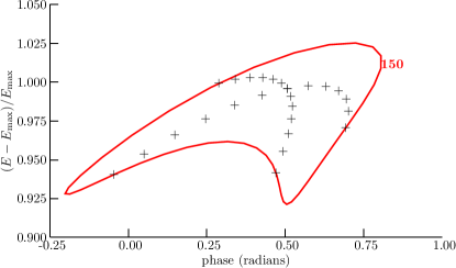
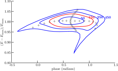
When tracking with rf is considered, the longitudinal dynamics behavior is complex S. Koscielniak and C. Johnstone (2003). If one begins with an upright ellipse, there is considerable emittance growth if only the 201.25 MHz rf is used (see Fig. 57). Adding a third-harmonic rf considerably reduces the emittance growth, as shown in Fig. 57. The amount of third-harmonic rf required is substantial and that, combined with space considerations, makes this alternative unattractive. Tilting the initial ellipse in phase space will reduce the emittance growth, but a means to produce that tilt must be developed.
V.2.4 FFAG Cost Optimization
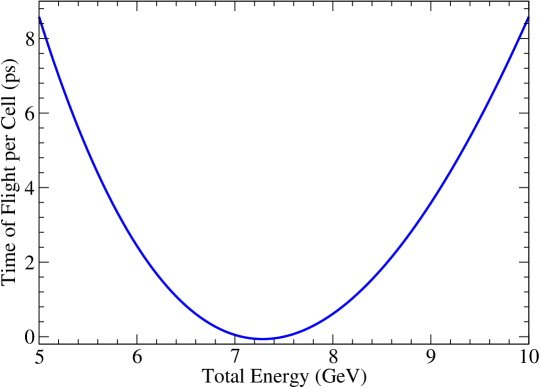
The designs for the FFAG lattices are chosen based on a cost optimization. The “costs” computed by our model are not intended to be used in computing the cost of an actual machine, but instead are used to find the cost of one design relative to another. For a given lattice type and a given energy range, the magnet lengths, their dipole fields, and their quadrupole fields are allowed to vary to produce the minimum cost for the lattice. Magnet apertures are determined by finding a circle that encloses all of the beam ellipses within a magnet (both at different energies and positions) for transverse amplitudes that are equal to the transverse acceptance. The difference between the time-of-flight at the minimum energy and the minimum time-of-flight for all energies (see Fig. 58) is constrained to be a certain value; similarly for the time-of-flight at the maximum energy. That value is chosen to make the quantity take on specific values. These values depend on the energy of the lattice, as well as the desired longitudinal acceptance. In the above equation, is the total rf voltage in the ring as an energy gain, is the angular rf frequency, is the time-of-flight difference described above, and is the energy range over which the beam is accelerated.
We examined FFAG lattice designs that minimize the relative cost. Some constraints were assumed in performing the optimization:
-
•
There is at least one 2-m-long drift in each cell to make room for a superconducting rf cavity. This is substantially longer than the rf cavity, but the extra length is needed to reduce the field from the magnets to below 0.1 T at the cavity surface M. Ono et al. (1999).
-
•
All shorter drifts in the cell are 0.5 m long. This is needed to maintain sufficient space between magnets for cryostats and other necessary equipment.
-
•
The minimum and maximum energy of each accelerating stage are fixed.
-
•
The type of lattice (doublet, triplet, FODO, etc.) is fixed.
-
•
The time-of-flight on the energy-dependent closed orbit is the same at the minimum and maximum energies (see Fig. 58). This minimizes the deviation of the bunch from the rf crest and therefore, presumably, maximizes the longitudinal acceptance of the lattice.
-
•
The quantity is a fixed value that depends on the energy range being considered. This value characterizes the longitudinal acceptance of the system.
-
•
The rf gradient is not allowed to exceed a specified value. Here we take a conservative value of 10 MV/m. This corresponds to a value that has already been achieved R.L. Geng et al. (2003).
| Minimum total energy (GeV) | 2.5 | 5 | 10 | ||||||
| Maximum total energy (GeV) | 5 | 10 | 20 | ||||||
| 1/6 | 1/8 | 1/12 | |||||||
| Type | FD | FDF | FODO | FD | FDF | FODO | FD | FDF | FODO |
| No. of cells | 65 | 60 | 76 | 79 | 72 | 91 | 93 | 85 | 105 |
| D length (cm) | 62 | 96 | 56 | 82 | 119 | 77 | 105 | 143 | 98 |
| D radius (cm) | 13.6 | 16.5 | 16.0 | 10.2 | 12.7 | 11.7 | 7.8 | 9.7 | 8.7 |
| D pole tip field (T) | 3.7 | 3.3 | 1.9 | 4.6 | 4.2 | 3.8 | 5.8 | 5.5 | 5.0 |
| F length (cm) | 99 | 48 | 93 | 126 | 64 | 119 | 162 | 85 | 151 |
| F radius (cm) | 19.1 | 15.8 | 22.8 | 15.3 | 12.8 | 17.8 | 12.7 | 10.9 | 14.6 |
| F pole tip field (T) | 2.2 | 2.4 | 1.7 | 2.8 | 3.1 | 2.2 | 3.5 | 3.7 | 2.8 |
| No. of cavities | 57 | 52 | 68 | 71 | 64 | 83 | 85 | 77 | 97 |
| RF voltage (MV) | 428 | 390 | 510 | 533 | 480 | 623 | 638 | 578 | 728 |
| 5.8 | 6.4 | 4.9 | 9.4 | 10.4 | 8.0 | 15.7 | 17.3 | 13.7 | |
| Circumference (m) | 268 | 295 | 418 | 362 | 393 | 543 | 481 | 521 | 681 |
| Decay (%) | 6.8 | 8.2 | 8.8 | 7.4 | 8.9 | 9.4 | 8.5 | 10.1 | 10.4 |
| Magnet cost (A.U.)111Arbitrary units | 36.4 | 41.6 | 49.6 | 32.8 | 37.4 | 40.0 | 34.1 | 39.2 | 38.4 |
| RF cost (A.U.) | 27.7 | 25.3 | 33.0 | 34.5 | 31.1 | 40.3 | 41.3 | 37.4 | 47.1 |
| Linear cost (A.U.) | 6.7 | 7.4 | 10.4 | 9.1 | 9.8 | 13.6 | 12.0 | 13.0 | 17.0 |
| Total cost (A.U.) | 70.8 | 74.3 | 93.1 | 76.3 | 78.3 | 93.8 | 87.4 | 89.6 | 102.5 |
| Cost per GeV (A.U.) | 28.3 | 29.7 | 37.2 | 15.3 | 15.7 | 18.8 | 8.7 | 9.0 | 10.2 |
To get an idea of what is achievable, we developed a set of cost-optimized lattices where a cavity is placed in every cell, except for 8 cells left open for injection and extraction hardware. The goal is to minimize the time spent accelerating and therefore minimize the decays. This drives the design toward a smaller ring but more rf. The results of this optimization are shown in Table 12. The costs are a significant improvement over the FS2 acceleration costs.
Table 12 leads to several conclusions:
-
•
The doublet lattice is the most cost-effective design. The triplet lattice requires less voltage, but has a higher magnet cost due to having more magnets per cell.
-
•
The cost per GeV of acceleration increases as the energy decreases. The RLA from FS2 has a cost per GeV around 30 in the units of Table 12, so this in some sense sets a baseline for determining when an FFAG approach becomes cost effective. Thus, a 2.5–5 GeV FFAG is borderline in its cost effectiveness, while the higher energy FFAGs are clearly cost effective.
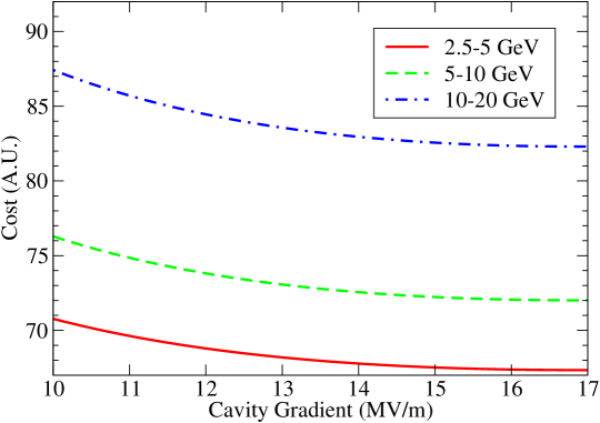
The effects of increasing the rf gradient on the costs of the doublet designs in Table 12 are shown in Fig. 59.
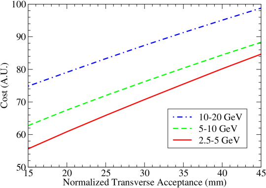
The choice of the acceptance also has a strong effect on the optimized cost, as shown in Fig. 60.
V.2.5 Design of Combined-Function Superconducting Magnet for FFAGs
An initial design of a superconducting combined-function (dipole–quadrupole) magnet has been developed S. Caspi and R. Hafalia (2004). A first-cut design of a superconducting combined function, dipole-quadrupole magnet, is outlined. The design is for one of the QD magnets requiring the highest field and gradient. The parameters of the QD cell are shown in Table 13,
| (GeV) | 10 |
|---|---|
| (GeV) | 20 |
| (m) | 2 |
| (m) | 0.5 |
| Type | QD |
| (m) | 1.762 |
| (m) | 18.4 |
| (mm) | 1.148 |
| (cm) | 10.3756 |
| (T) | 2.7192 |
| (T/m) | -15.495 |
where is the length of the long drift between the QF magnets, is the length of the short drift between QF and QD magnets; is the length of the reference orbit inside the magnet, is the radius of curvature of the reference orbit, is the displacement of the center of the magnet from the reference orbit, is the radius of the magnet bore, is the vertical magnetic field at the reference orbit, and is the derivative of the vertical magnetic field at the reference orbit.
The magnet design is based on a cosine-theta configuration with two double layers for each function. The quadrupole coil is located within the dipole coil and both coils are assembled using key-and-bladder technology. All coils are made with the same Nb–Ti cable capable of generating the operating dipole field and gradient with about the same current of 1800 A (a single power supply is thus possible with a bit of fine tuning). The maximum central dipole field and gradient at short sample are 4.1 T and 26 T/m, as compared with the requirements of 2.7 T and 15.4 T/m, respectively. At this early design stage, excess margin is left for safety and perhaps a field-rise in the magnet end region. The maximum azimuthal forces required for magnet pre-stress are of the order of 1 MN/m (assuming maximum safety). The conductor strand size and cable parameters common to both dipole and quadrupole are listed in Table 14.
| Strand diameter (mm) | 0.6477 |
| Cable width, bare (mm) | 6.4 |
| Cable thickness, insulated (mm) | 1.35 |
| Keystone angle (deg.) | 0.6814 |
| Conductor type | Nb–Ti |
| Cu:SC ratio | 1.8:1 |
| Current density (at 5 T, 4.2 K) (A/mm2) | 2850 |
| Number of strands | 20 |
The initial cross sections of both dipole and quadrupole were designed to give less than one part in one hundred units of systematic multipole errors at a radius of 70 mm. It is straightforward to readjust the design to cancel the end-field multipoles as proposed in Section V.2. The combined cross section is shown in Fig. 61 for one quadrant. Figure 62 shows the combined dipole-quadrupole magnetic flux. The calculated mid-plane field profile of the magnet (plotted in Fig. 63) clearly shows the superposed dipole and quadrupole fields. A mechanical layout for the magnet has also been developed, as shown in Figs. 64, 65, and 66.
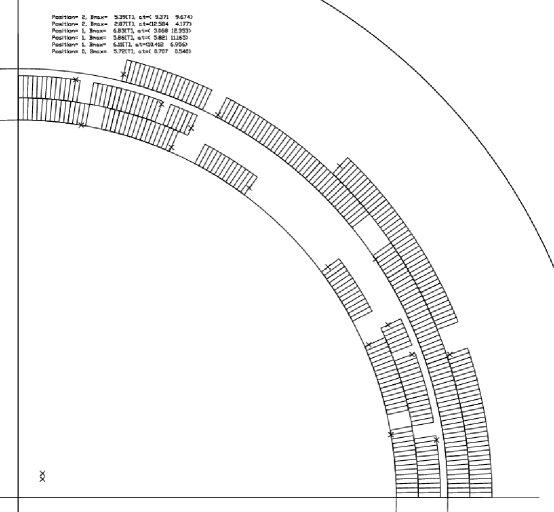
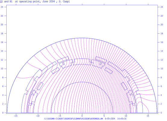
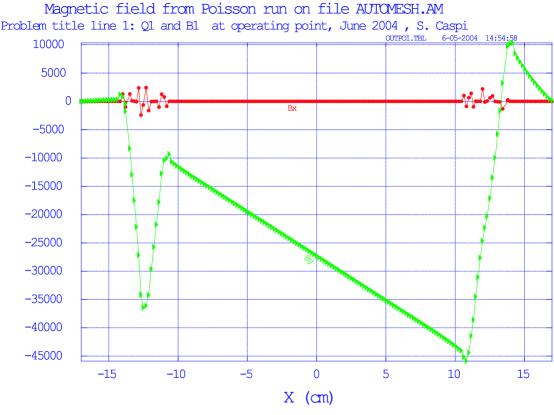
| Current density (A/mm2) | Central Field (T) | Gradient |
|---|---|---|
| 730 | 2.5 | 15.4 |
| 800 | 2.7 | 17 |
| 1220 (maximum) | 4.1 | 26 |
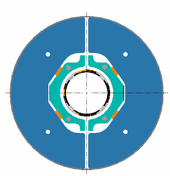
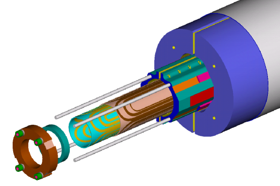
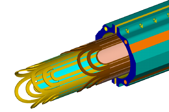
V.3 Considerations on a Beta Beam Facility in the U.S.
Motivated by the recent suggestion that a higher energy Beta Beam facility might have considerable scientific merit J. Burguet-Castell, D. Casper, J.J. Gomez-Cadenas, P. Hernandez, F. Sanchez (2004), we consider here some of the possibilities of a U.S.-based scenario. There was neither the time nor the effort available to carry out a study equivalent to the baseline scenario prepared by the European Beta Beam Study Group, and we make no pretense of having done so. Nonetheless, it was felt to be interesting to look briefly at U.S. options that have the potential for higher energy beams than likely to be available at CERN in the foreseeable future. In particular, an “intermediate” beam energy of which corresponds well to the top energy available at the Tevatron, is expected to have much better resolution than the CERN low-energy option in terms of both CP violation and sensitivity to the mass hierarchy.
The two possible U.S. machines to consider are RHIC at BNL and the Tevatron at Fermilab. Of these, the Tevatron looks more attractive due to its higher energy reach. (RHIC has a top energy comparable to the SPS at CERN.) Both BNL and Fermilab are interested in Superbeams, which complement the Beta Beam in terms of physics reach, and both Laboratories are pursuing the possibility of obtaining a high-intensity proton driver, a prerequisite for a Superbeam and helpful, but not critical, for a Beta Beam facility. It is worth noting, of course, that an intermediate-energy Beta Beam facility would require a very large decay ring to store a beam. This would add substantially to the cost of implementing such a facility in the U.S.
V.3.1 Estimate of Decay Losses
It is important to know how many ions survive the acceleration process without decaying. This can be calculated as
| (20) |
where is the decay time at rest. If the ramp rate is constant, the integral (which represents the time passed in the rest frame) becomes
| (21) |
Here, is the ramp time, the initial energy, and final energy. In most accelerators, the energy changes by an order of magnitude (), so
| (22) |
Substituting this back into Eq. (20) yields
| (23) |
which is just the standard decay formula with the decay time calculated at an “effective” or average energy equal to 40% of the top energy. In reality, the ramp rate is not constant. In particular, the start of the ramp is usually slower, leading to a larger total decay than the above estimate would predict. Nonetheless, Eq. (23) gives a useful first approximation. If a more accurate result were needed, and the ramp function is known, losses could be calculated directly from Eq. (20).
To calculate the Lorenz gamma of the ions, based on the corresponding gamma of full energy protons in the same machine, we recall that the magnetic rigidity is the same for both particles:
| (24) |
which, since the momentum is
| (25) |
gives
| (26) |
where is the charge-to-mass ratio of the ion.
Table 16 lists the U.S. machines relevant to Beta Beam acceleration, and their maximum gamma for protons, 6He and 18Ne. Table 17 gives the approximate amount of beam loss due to beta decay during acceleration. Due to its long ramp time, it is clear that RHIC would not be very efficient at accelerating the ions in question. The Tevatron, on the other hand, would be relatively efficient, as it was originally designed as a fixed-target machine and hence has a reasonably fast ramp. The Tevatron has the additional feature of being, for now, the world’s highest energy machine. Assuming that the LHC will be busy with collider physics for the foreseeable future, the Tevatron would thus seem to be the obvious candidate for generating an “intermediate energy” Beta Beam. There remains one key question, however—we must assess how the Tevatron’s superconducting magnets would be affected by the decay products of the Beta Beam. This, in turn, determines how many ions the machine could accelerate to top energy in a single batch. If there is continued interest in exploring the possibility of using the Tevatron for an intermediate energy Beta Beam facility, this issue must be studied.
| Machine | Proton kinetic energy (GeV) | |||
|---|---|---|---|---|
| FNAL Booster | 8 | 9.5 | 3.3 | 5.4 |
| Main Injector | 150 | 161 | 64 | 89 |
| Tevatron | 980 | 1045 | 349 | 581 |
| BNL Booster | 2 | 3.1 | 1.4 | 1.9 |
| AGS | 30 | 34 | 11 | 19 |
| RHIC | 250 | 268 | 89 | 149 |
| Machine | Ramp time (s) | loss (%) | loss ( %) |
|---|---|---|---|
| FNAL Booster | 0.03 | 2 | 1 |
| Main Injector | 0.7 | 2 | 1 |
| Tevatron | 17 | 10 | 3 |
| BNL Booster | 0.1 | 14 | 5 |
| AGS | 0.5 | 9 | 3 |
| RHIC | 100 (40) | 91 (62) | 50 (24) |
V.3.2 Estimate of Power Deposition
The total deposited power from decay products per unit machine length can be written
| (27) |
where, is the number of decays per unit of time, is the decay time at rest, and is the rest energy. For high energies (), the deposited power is independent of gamma, depending only on the number of ions per machine length. To obtain the time-averaged power, one must multiply by the duty factor (fraction of time with beam in the machine)
| (28) |
For the Tevatron, this equation can be used to estimate the number of ions that would generate 1 W/m from decay losses, which is about for both types of ions. For the lower energy machines, supplying the Tevatron with this intensity would yield much lower power deposition, even though their circumferences are smaller. This is because their duty factor (ramp time divided by Tevatron cycle time) is very small. Anticipated levels are about 0.05 W/m in the Main Injector, and 0.03 W/m in the Booster, based on the simplified formula above.
VI Neutrino Factory and Beta Beam R&D
As should be clear from the design descriptions in Section V, both the muon-based Neutrino Factory and the Beta Beam facility are demanding projects. Both types of machine make use of novel components and techniques that are, in some cases, at or beyond the state of the art. For this reason, it is critical that R&D efforts to study these matters be carried out. In this Section we describe the main areas of R&D effort under way in support of the two projects. We give an overview of the R&D program goals and list the specific questions we expect ultimately to answer. We also summarize briefly the R&D accomplishments to date and give an indication of R&D plans for the future.
Since neither of these projects is expected to begin construction in the near future, it might be asked why it is necessary to pursue a vigorous R&D program now. One answer is that this R&D is what allows us to determine—with some confidence—both the expected performance and expected cost of such machines. This information must be available in a timely way to permit the scientific community to make informed choices on which project(s) they wish to request at some future time. Experience has shown that large, complex accelerator projects take many years of preparatory R&D in advance of construction. It is only by supporting this R&D effort now that we can be ready to provide a Neutrino Factory or Beta Beam facility when the proper time comes.
VI.1 Neutrino Factory R&D
Successful construction of a muon storage ring to provide a copious source of neutrinos requires many novel approaches to be developed and demonstrated; a high-luminosity Muon Collider, which might someday follow, would require an even greater extension of the present state of accelerator design. Thus, reaching the desired facility performance requires an extensive R&D program. Each of the major systems has significant issues that must be addressed by R&D activities. Component specifications need to be verified. For example, the cooling channel assumes a normal conducting rf (NCRF) cavity gradient of 15 MV/m at 201.25 MHz, and the acceleration section demands similar performance from superconducting rf (SCRF) cavities at this frequency. In both cases, the requirements are beyond the performance reached to date for cavities in this frequency range. The ability of the target to withstand a proton beam power of up to 4 MW must be confirmed. Finally, an ionization cooling experiment should be undertaken to validate the implementation and performance of the cooling channel, and to confirm that our simulations of the cooling process are accurate.
VI.1.1 R&D Program Overview
A Neutrino Factory comprises the following major systems: Proton Driver; Target, (Pion) Capture, and (Pion-to-Muon) Decay Section; Bunching and Phase Rotation Section; Cooling Section; Acceleration Section; and Storage Ring. The R&D program we envision is designed to answer first the key questions needed to embark upon a Zeroth-order Design Report (ZDR). The ZDR will examine the complete systems of a Neutrino Factory, making sure that nothing is forgotten, and will show how the parts merge into a coherent whole. While it will not present a fully engineered design with a detailed cost estimate, enough detail will be presented to ensure that the critical items are technically feasible and that the proposed facility could be successfully constructed and operated at its design specifications. By the end of the full R&D program, it is expected that a formal Conceptual Design Report for a Neutrino Factory could begin. The CDR would document a complete and fully engineered design for the facility, including a detailed bottom-up cost estimate for all components. This document would form the basis for a full technical, cost, and schedule review of the construction proposal, subsequent to which construction could commence (assuming strong community support and government approval). The R&D issues for each of the major systems must be addressed by a mix of theoretical, simulation, modeling, and experimental studies, as appropriate. A list of the key physics and technology issues for each major Neutrino Factory system is given below. These issues are being actively pursued as part of the ongoing worldwide Neutrino Factory R&D program, with participation from Europe, Japan, and the U.S.
Proton Driver
-
•
Production of intense, short proton bunches, e.g., with space-charge compensation and/or high-gradient, low frequency rf systems
Target, Capture, and Decay Section
-
•
Optimization of target material (low-Z or high-Z) and form (solid, moving band, liquid-metal jet)
-
•
Design and performance of a high-field solenoid (20 T) in a very high radiation environment
Bunching and Phase Rotation Section
-
•
Design of efficient and cost-effective bunching system
-
•
Examination of alternative approaches, e.g., based upon combined rf phase rotation and bunching systems or fixed-field, alternating gradient (FFAG) rings
Cooling Section
-
•
Development and testing of high-gradient normal conducting rf (NCRF) cavities at a frequency near 200 MHz
-
•
Development and testing of efficient high-power rf sources at a frequency near 200 MHz
-
•
Development and testing of LH2, LiH, and other absorbers for muon cooling
-
•
Development and testing of candidate diagnostics to measure emittance and optimize cooling channel performance
Acceleration Section
-
•
Optimization of acceleration techniques to increase the energy of a muon beam (with a large momentum spread) from a few GeV to a few tens of GeV (e.g., recirculating linacs, rapid cycling synchrotrons D.J. Summers, J.S Berg, A.A. Garren, R.B. Palmer (2003), FFAG rings)
-
•
Development of high-gradient superconducting rf (SCRF) cavities at frequencies near 200 MHz, along with efficient power sources (about 10 MW peak) to drive them
-
•
Design and testing of components (rf cavities, magnets, diagnostics) that will operate in the muon-decay radiation environment
Storage Ring
-
•
Design of large-aperture, well-shielded superconducting magnets that will operate in the muon-decay radiation environment
VI.1.2 Recent R&D Accomplishments
Targetry
The BNL Targetry experiment, E951, has carried out initial beam tests A. Hassenein et al. (2003) of both a solid carbon target and a mercury target at a proton beam intensity of about ppp. In the case of the solid carbon target, it was found that a carbon-carbon composite having nearly zero coefficient of thermal expansion is largely immune to beam-induced pressure waves. A carbon target in a helium atmosphere is expected to have negligible sublimation loss. A program to verify this is under way at ORNL T. Gabriel and J. Haines (2004). If radiation damage is the limiting effect for a carbon target, the predicted lifetime would be about 12 weeks when bombarded with a 1 MW proton beam.
For a mercury jet target, tests with about 2 1012 ppp showed that the jet is not dispersed until long after the beam pulse has passed through the target (see Fig. 67). Measurements of the velocity of droplets emanating from the jet as it is hit with the proton beam pulse from the AGS (10 m/s for 25 J/g energy deposition) compare favorably with simulation estimates. High-speed photographs indicate that the beam disruption at the present intensity does not propagate back upstream toward the jet nozzle. If this remains true at the higher intensity of 1.6 1013 ppp, it will ease mechanical design issues for the nozzle.
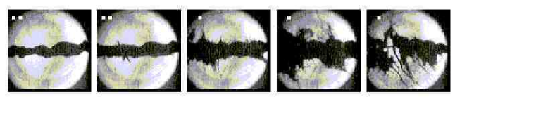
MUCOOL
A primary effort has been to carry out high-power tests of 805-MHz rf cavities in the Lab G test area at Fermilab. A 5-T test solenoid for the facility, capable of operating either in solenoid mode (its two independent coils powered in the same polarity) or gradient mode (with the two coils opposed), was used to study the effects of magnetic field on cavity performance. Most recently, a single-cell 805-MHz pillbox cavity (Fig. 68) having Be foils to close the beam iris was tested. This cavity permitted an assessment of the behavior of the foils under rf heating and was used to study dark current effects J. Norem, et al. (2003). The cavity reached 40 MV/m (exceeding its design specification) in the absence of a magnetic field, but was limited by breakdown to less than 15 MV/m at high magnetic field ( T). Understanding the effects of the magnetic field on cavity performance is crucial, as this is the environment required for cavities in a muon cooling channel.
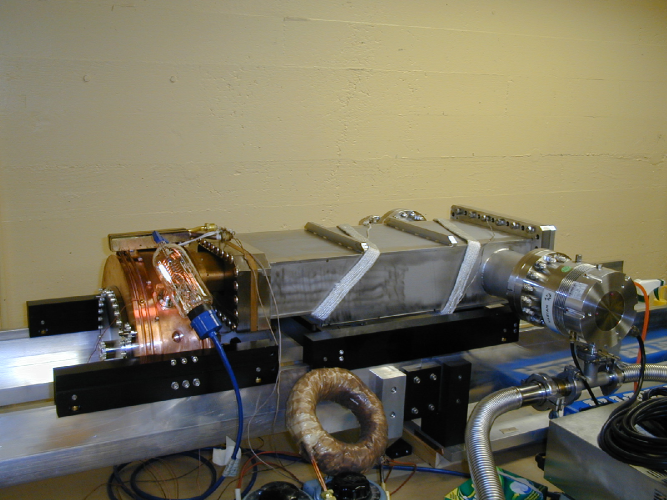
Development of a prototype LH2 absorber, the material chosen for FS2 and also for MICE Edgecock (2003) (the Muon Ionization Cooling Experiment, see Section VI.1.4) is well along. Several large diameter, thin (125–350 m) aluminum windows have been successfully fabricated by machining from solid disks. These have been pressure tested with water and found to break at a pressure consistent with finite-element design calculations M.A. Cummings et al. (2003). Another absorber material that must be studied is LiH, the material on which the cooling channel used in this report is based. In the new scheme, the LiH serves both as an absorber and an rf window. This configuration could be tested in the 805-MHz pillbox cavity described above. A new area, the MUCOOL Test Area (MTA), is nearly completed at FNAL and will be used for initial testing of the liquid-hydrogen absorbers. It will also have access to both 805-MHz and 201-MHz high-power rf amplifiers for continuing rf tests of the 805-MHz pillbox cavity and, soon, for testing a prototype 201-MHz cavity. The MTA is located at the end of the Fermilab proton linac, and is designed to eventually permit beam tests of components and detectors with 400 MeV protons.
Beam Simulations and Theory
Subsequent to work on FS2, present effort has focused on further optimization of Neutrino Factory performance and costs. The more cost effective front-end design reported in this paper is a result of this work.
SCRF Development
This work is aimed at development of a high-gradient 201-MHz SCRF cavity for muon acceleration. (The choice of SCRF for a cooling channel is excluded because of the surrounding high magnetic field; the acceleration system does not suffer this limitation.) A test area of suitable dimensions was constructed at Cornell (Fig. 69) and used to test a prototype cavity fabricated for the Cornell group by CERN colleagues. The cavity reached 11 MV/m in initial tests, but exhibited a significant “ slope” as the gradient increased R.L. Geng et al. (2003). To better understand the origins of this phenomenon, effort will shift to studies on a smaller 500 MHz cavity. Different coating and cleaning techniques will be explored to learn how to mitigate the observed slope.
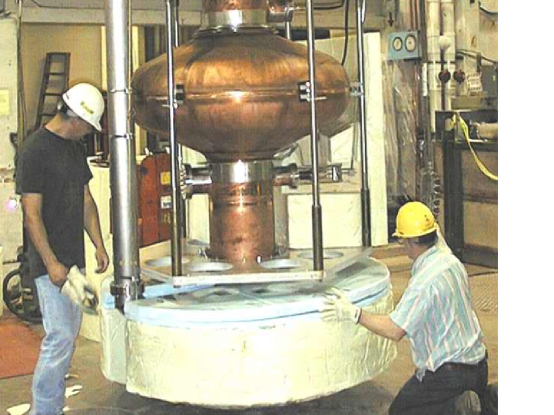
VI.1.3 R&D plans
Targetry
For the targetry experiment, design of a pulsed solenoid and its power supply are under way. A cost-effective design capable of providing up to a 15 T field has been developed (see Fig. 70).
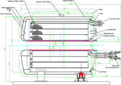
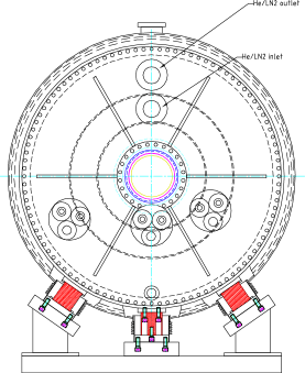
Tests of a higher velocity mercury jet (about 20 m/s velocity, compared with about 2.5 m/s in the jet system initially tested), will be carried out. To complement the experimental program, target simulation efforts are ongoing. These aim at a sufficiently detailed understanding of the processes involved to reproduce the observed experimental results both with and without a magnetic field. Fully 3D magneto-hydrodynamics codes are being utilized for this effort.
MUCOOL
Further testing work for 805 MHz components will continue in the MTA. Work will focus on understanding and mitigating dark current and breakdown effects at high gradient. Many aspects of cavity design, such as cleaning and coating techniques, will be investigated. In addition, tests of alternative designs for window or grid electromagnetic terminations for the rf cavity will be initially explored to identify the best candidates for the full-sized 201 MHz prototype cavity. Fabrication of the 201 MHz cavity by a group from LBNL, Jlab, and the University of Mississippi is nearly completed. This cavity will also be tested in the MTA. Thermal tests of a prototype absorber in the MTA are just getting under way. Fabrication of other cooling channel components required for the initial phase of testing will be carried out, including a large-bore superconducting solenoid, and diagnostics that could be used for the experiment. With these components, it will be possible eventually to assemble and bench test a full prototype cell of a realistic cooling channel. Provision will be made to test curved Be windows and grids in the 805 MHz cavity, followed by tests on the 201 MHz prototype. As already noted, the site of the MTA was selected with the goal of permitting beam tests of the cooling channel components with a high intensity beam of 400 MeV protons. While not the same as using an intense muon beam, such a test would permit a much better understanding of how the cooling channel would perform operationally, especially the high-gradient rf cavity and the LH2 or LiH absorber.
Beam Simulations and Theory
A major simulation effort will continue to focus on iterating the front-end channel design to optimize it for cost and performance. Further effort will be given to beam dynamics studies in the FFAG rings and storage ring, including realistic errors. Work on optimizing the optics design will be done. Assessment of field-error effects on the beam transport will be made to define acceptance criteria for the magnets. This will require use of sophisticated tracking codes, such as COSY K. Makino and M. Berz (1999), that permit rigorous treatment of field errors and fringe-field effects. In many ways, the storage ring is one of the most straightforward portions of a Neutrino Factory complex. However, beam dynamics is an issue here as the muon beam must circulate for many hundreds of turns. Use of a tracking code such as COSY is required to assess fringe field and large aperture effects. As with the FFAG rings, the relatively large emittance and large energy spread enhance the sensitivity to magnetic field and magnet placement errors. Suitable magnet designs are needed, with the main technical issue being the relatively high radiation environment. Another lattice issue that must be studied is polarization measurement. In the initial implementation of a Neutrino Factory it is expected that polarization will not be considered, but its residual value may nonetheless be important in analyzing the experiment. Simulation efforts in support of MICE will continue. We also plan to participate in a so-called “World Design Study” of an optimized Neutrino Factory. This study, an international version of the two previous U.S. Feasibility Studies, will likely be hosted in the UK by Rutherford Appleton Laboratory (RAL), the site for the MICE experiment (see Section VI.1.4). It will be organized jointly by representatives from Europe, Japan, and the U.S.
SCRF Development
A prototype 500 MHz SCRF cavity will be used to study the slope phenomenon, with the goal of developing coating and cleaning techniques that reduce or eliminate it. Detuning issues at 201 MHz associated with the very large cavity dimensions and the pulsed rf system will be evaluated. Tests of the 201 MHz SCRF cavity will include operation in the vicinity of a shielded solenoid magnet, to demonstrate our ability to adequately reduce nearby magnetic fields in a realistic lattice configuration. If funds permit, design of a prototype high-power rf source will be explored, in collaboration with industry. This source—presently envisioned to be a multibeam klystron—must be developed for operation at two different duty factors, because the cooling channel requires a duty factor of about 0.002 whereas the acceleration chain requires 0.045. Magnet designs suitable for the FFAG rings and the muon storage ring will be examined further. Both conventional and superconducting designs will be compared where both are possible. With SC magnets, radiation heating becomes an issue and must be assessed and dealt with.
VI.1.4 Cooling Demonstration Experiment
Clearly, one of the most important R&D tasks that is needed to validate the design of a Neutrino Factory is to measure the cooling effects of the hardware we propose. Participation in the International Muon Ionization Cooling Experiment (MICE) will accomplish this, and is therefore expected eventually to grow into a primary activity. Unquestionably, the experience gained from this experiment will be invaluable for the design of an actual cooling channel.
At the NUFACT’01 Workshop in Japan, a volunteer organization was created to organize a cooling demonstration experiment that might begin as soon as 2004. Membership in this group includes representatives from Europe, Japan, and the U.S. The experimental collaboration now numbers some 140 members from the three geographical regions. The MICE Collaboration has received scientific approval for the experiment from RAL management, and is now in the process of seeking funding. The experiment will involve measuring, on a particle-by-particle basis, the emittance reduction produced by a single cell of the FS2 cooling channel. A schematic of the layout is shown in Fig. 71. The cooling channel cell is preceded and followed by nearly identical detector modules that accomplish particle identification and emittance measurement. Provision for testing a series of absorber materials, including both LH2 and solid absorbers, has been made. A preliminary safety review of the liquid-hydrogen system has been successfully passed, and permission to begin detailed engineering has been granted.
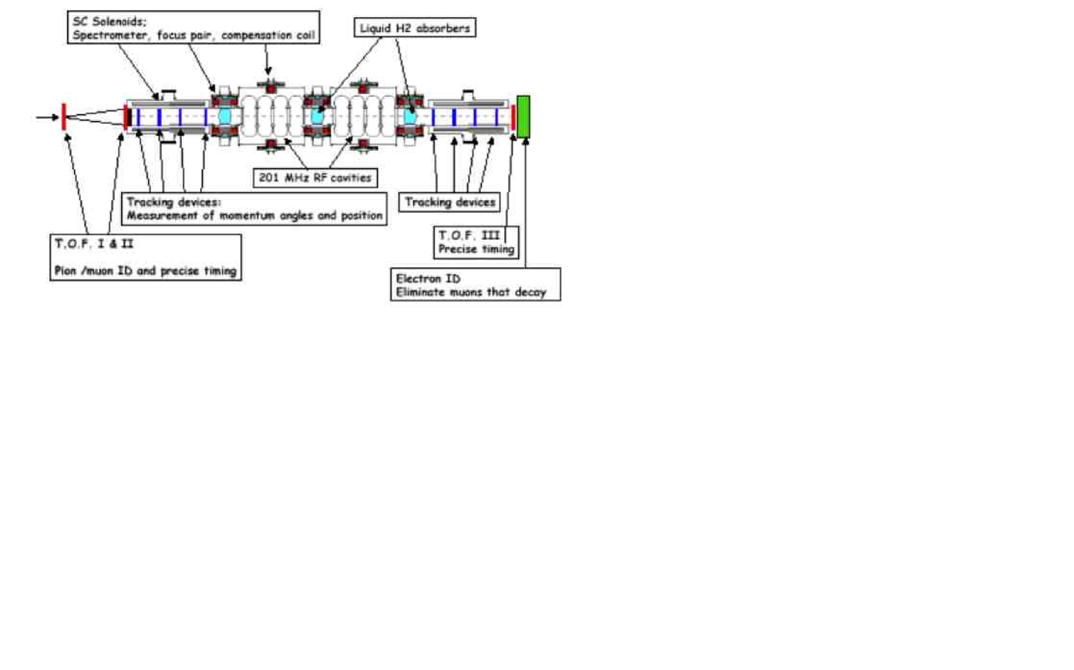
VI.2 Beta Beam R&D
Constructing a Beta Beam facility requires a number of new techniques to be developed. In the CERN-based scenario, where the facility incorporates a number of existing machines, a significant technical challenge is to ensure that the proposed parameters for the Beta Beam case are compatible with the capabilities of the present accelerators. If not, required modifications must be identified and demonstrated. An additional constraint in the CERN scenario—or a corresponding U.S. scenario based on existing machines—is that the modifications to accommodate Beta Beams must maintain compatibility with existing programs. There are several significant challenges in providing Beta Beams of the required intensity, and R&D is required to validate the concepts proposed to deal with them. These issues include:
-
•
Target: To provide the required ion intensities, the target must be able to handle the driver beam intensity for a reasonable lifetime. While the production of 6He looks fairly straightforward, the production of 18Ne is less so. The baseline production method for 18Ne relies on direct bombardment of the target material with the proton beam. Determining what intensity is acceptable to maintain a reasonable target lifetime must be done. The alternative production technique suggested for 18Ne, namely the 16O(3He,n) reaction, clearly requires a different incoming beam, which might require an additional driver accelerator. In the scenario where the outputs from three targets are combined, techniques for splitting the driver beam into multiple paths and combining the target outputs into a single ion source need to be worked out and tested. Since the ion source must necessarily be remote from the highly active target area, good transport efficiency for the nuclides of interest must be demonstrated.
-
•
Ion Source: With an ISOL-type production system, the ions are produced continuously. To prepare the beam for acceleration, it must then be bunched considerably, to below s. It is proposed to get the required intensity and bunch structure by using a new ion source concept, with state-of-the-art specifications. The source is an ECR source operating at high frequency (60 GHz) with a high magnetic field (2–3 T) and high plasma density Such a source has never been built, though a development effort is now under way at Grenoble sor . It will be necessary to study the influence of the carrier gas on the ionization efficiency. Also, the ability to produce fully stripped beams of 18Ne must be demonstrated. Typically ECR sources produce high charge states, but not so high as Ne Even with an enhanced ion source of the type proposed, the expected J. Bouchez, M. Lindroos, and M. Mezzetto antineutrino intensity is per “Snowmass year” (1 107 s), and that for neutrinos (assuming that the outputs from three production targets are combined) is
-
•
Decay Losses: The losses in the low-energy portion of the accelerator chain are high because the beam is intense and its relativistic is low. In the CERN scenario, the PS is somewhat vulnerable as it has already accumulated a high radiation dose over its operational lifetime and its cycle time is not rapid. For 6He, the PS losses are estimated M. Lindroos to be about 1.2 W/m while those in the storage ring are 28 W/m. In the latter case, specially designed superconducting magnets with no coils in the midplane are required to avoid quenches. (A variant of this approach is used for the muon storage ring of a Neutrino Factory, for the same reason.) Building prototype magnets and measuring their field quality and quench resistance should be undertaken to validate the proposed approach.
-
•
Storage Ring Issues: Since the storage ring must be frequently topped off, injection requires the use of bunch-merging techniques. A concept has been worked out for this, and an initial test was encouraging. Since many of the problems with rf manipulation techniques are intensity dependent, it will probably still be necessary to validate the proposed scheme under fully realistic conditions. The recent proposal to run both 6He and 18Ne beams simultaneously in the decay ring is another non-trivial complication. At the same rigidity, the heavier beam has a relativistic that is that of the lighter beam, so the orbits must be adjusted to provide the same revolution period. This may well have some beam dynamics implications for the off-center beam, given that the proposed magnets may not have ideal fields far off axis. It will certainly complicate beam manipulations for the two beams, especially the injection and bunch merging. Another issue that needs to be evaluated in detail is the influence of the beam parameters (orbits, emittance, beta functions) on the neutrino spectrum at the detector.
VII Summary
Two new types of facility have been proposed that could have a tremendous impact on future neutrino experiments—the Neutrino Factory and the Beta Beam facility. In contrast to conventional muon-neutrino beams, Neutrino Factory and Beta Beam facilities would provide a source of electron-neutrinos and -antineutrinos , with very low systematic uncertainties on the associated beam fluxes and spectra. The experimental signature for transitions is extremely clean, with very low background rates. Hence, Neutrino Factories and Beta Beams would enable very sensitive oscillation measurements to be made. This is particularly true at a Neutrino Factory which not only provides very intense beams at high energy, but also provides muon-neutrinos and -antineutrinos in addition to electron-neutrinos and -antineutrinos . This would facilitate a large variety of complementary oscillation measurements in a single detector, and dramatically improve our ability to test the three-flavor mixing framework, measure CP violation in the lepton sector (and perhaps determine the neutrino mass hierarchy), and, if necessary, probe extremely small values of the mixing angle .
At this time, we do not know the value of . If , much of the basic neutrino oscillation physics program will be beyond the reach of conventional neutrino beams. In this case Neutrino Factories and Beta Beams offer the only known way to pursue the desired physics program.
The sensitivity that could be achieved at a Beta Beam facility presently looks very promising, but is still being explored. In particular, the optimum Beta Beam energy is under discussion. Low energy Beta Beam measurements would complement Superbeam measurements, but would achieve a sensitivity that does not appear to be competitive with that of a Neutrino Factory. Higher energy Beta Beams may approach the sensitivity possible with a Neutrino Factory, although systematics issues need further study. Thus, while a Beta Beam facility may have a significant role to play in the future global neutrino program, more work must be done on its design, development, cost estimate, and physics sensitivity to validate its potential. We note that, due to very limited resources, there has been no significant activity in the U.S. on Beta Beams. Progress on Beta Beam development being made in Europe should be followed, especially if the higher energy solution continues to look favorable.
An impressive Neutrino Factory R&D effort has been ongoing in the U.S. and elsewhere over the last few years, and significant progress has been made towards optimizing the design, developing and testing the required accelerator components, and significantly reducing the cost, even during the current Study. (Although a full engineering study is required, we have preliminary indications that the unloaded cost of a Neutrino Factory facility based on an existing Superbeam proton driver and target station can be reduced substantially compared with previous estimates.) Neutrino Factory R&D has reached a critical stage in which support is required for two key international experiments (MICE and Targetry) and a third-generation international design study. If this support is forthcoming, a Neutrino Factory could be added to the Neutrino Physics roadmap in about a decade.
Given the present uncertainty about the size of it is critical to support an ongoing and increased U.S. investment in Neutrino Factory accelerator R&D to maintain this technical option. A Neutrino Factory cannot be built without continued and increased support for its development. We note that the 2001 HEPAP Report advocated an annual U.S. investment of $8M on Neutrino Factory R&D. The present support is much less than this. Since R&D on the design of frontier accelerator facilities takes many years, support must be provided now to have an impact in about a decade.
VIII Recommendations
Accelerator R&D is an essential part of the ongoing global neutrino program. Limited beam intensity is already constraining the neutrino physics program, and will continue to do so in the future. More intense and new types of neutrino beams would have a big impact on the future neutrino program. A Neutrino Factory would require a Superbeam-type MW-scale proton source. We thus encourage the rapid development of a Superbeam-type proton source.
The Neutrino Factory and Beta Beam Working Group’s specific recommendations are:
-
•
We recommend that the ongoing Neutrino Factory R&D in the U.S. be given continued encouragement and financial support. We note that the HEPAP Report of 2001 recommended an annual support level of $8M for Neutrino Factory R&D, and this level was considered minimal to keep the R&D effort viable.
In addition, and consistent with the above recommendation,
-
1.
We recommend that the U.S. funding agencies find a way to support the international Muon Ionization Cooling Experiment (MICE), in collaboration with European and Japanese partners. We note that MICE now has scientific approval at the Rutherford Appleton Laboratory in the UK, and will require significant U.S. participation. This has been identified as an important experiment for the global Neutrino Factory R&D program. A timely indication of U.S. support for MICE is needed to move the experiment forward.
-
2.
We recommend that support be found to ensure that the international Targetry R&D experiment proceeds as planned. We note that this R&D activity is crucial for the short-, medium-, and long-term neutrino programs, and for other physics requiring high-intensity beams.
-
3.
We recommend that a World Design Study, aimed at solidly establishing the cost of a cost-effective Neutrino Factory, be supported at the same level as Studies I and II. We note that the studies done here suggest that the cost of a Neutrino Factory would be significantly less than estimated for Studies I and II. This makes a Neutrino Factory a very attractive ingredient in the global neutrino roadmap.
-
1.
-
•
We recommend that progress on Beta Beam development be monitored, and that our U.S. colleagues cooperate fully with their EU counterparts in assessing how U.S. facilities might play a role in such a program. We note that there is no significant U.S. R&D effort on Beta Beams due to our limited R&D resources. Insofar as an intermediate energy solution is desirable, however, the Beta Beam idea is potentially of interest to the U.S. physics community.
Acknowledgements.
This research was supported by the U.S. Department of Energy under Contracts No. DE-AC02-98CH10886, No. DE-AC02-76CH03000, and No. DE-AC03-76SF00098.IX Appendix A
IX.1 Cost Reduction
Here we present the cost scaling we have done with respect to FS2 cost numbers S. Ozaki, R. Palmer, M. Zisman, and J. Gallardo, eds. (2001). Since there was neither time nor engineering effort available to perform a bottom-up cost estimate for the new systems we have developed during the present Study, we have based our costs on the FS2 numbers and scaled them appropriately to derive the estimated savings from our new technical approaches. For that reason, we quote the results as a percentage of the original FS2 estimates, to avoid giving the impression that this is anything more than a “physicist’s estimate” at this point in time.
The method we employed was as follows:
-
•
Starting from the FS2 Work Breakdown Structure system costs, we derive useful element costs per unit length, per integral rf voltage, or per unit acceleration.
-
•
We then applied these scaling rules to the new parameters derived from this Study (see Section V) to obtain a first approximation to the revised cost. Our results are reported as costs relative to FS2. We have ignored minor corrections, such as escalating the costs to FY2004 dollars, as these are small compared with the precision of our estimate.
-
•
Because it is expected that a future Neutrino Factory would be built as an “upgrade” or follow-on to a Superbeam facility, we think it likely that the Proton Driver—and quite possibly the Target facility as well—will already exist at the time the Neutrino Factory construction commences. For this reason, our costs are given with and without including the Proton Driver or Target Station.
Based on the costing approach we used, we expect that the unloaded hardware cost of the updated Neutrino Factory design will be reduced by about one-third compared with the original FS2 cost estimate of $1.8B (see Table 18).
| All | No Driver | No Driver, No Target | |
| ($M) | ($M) | ($M) | |
| TOTAL222No “other”, no EDIA, no contingency. | 1832 | 1641 | 1538 |
IX.1.1 Proton Driver
The cost basis for FS2 was an upgrade of the AGS to 1 MW beam power. The cost used here is taken without change from FS2. As noted earlier, we anticipate that this component would already be in place to support a prior Superbeam experiment. In that case, it would not be part of the cost to construct a Neutrino Factory. Since the Proton Driver tends to be the most site-specific component of a Neutrino Factory, we expect the remaining costs to be largely site independent.
IX.1.2 Target and Capture
The updated Target and Capture system is almost the same as that in FS2, but differs in the details. In particular, the region over which the field tapers down is shorter by 5.5 m because it tapers only to 1.75 T rather than the 1.25 T used in FS2. The cost will thus be somewhat less. We estimated this savings by subtracting the cost of 5.5 m of a 1.25 T transport channel, whose cost per meter was taken from the drift region in FS2. This is a conservative estimate, because the section eliminated had fields varying from 1.75 T to 1.25 T, whereas the savings are estimated assuming lower field transport at 1.25 T.
IX.1.3 Drift Region
The first 18 m of drift is more expensive than later beam transport sections because of the required radiation shielding. We therefore treat this first 18 m of drift separately from the subsequent transport. To evaluate the cost, we took the FS2 costs for the first 18 m, and then made a correction due to the higher solenoid field in the new channel compared with FS2 (1.75 T vs. 1.25 T). Specifically, the correction involved increasing the magnet, power supply, and cryogenic costs using the second scaling formula from Green et al. M. A. Green, R. Byrns, S.J.St. Lorant (1992),
| (29) |
The subsequent 82 m drift requires less shielding and will thus be less expensive. In FS2, there was no equivalent simple drift from which to scale this cost. Therefore, we estimated the costs based on the magnets, power supplies, and cryogenics included in the induction linac region of FS2. As these costs were for 1.25 T magnets, we corrected for the higher 1.75 T field using Eq. 29. This estimate is quite conservative, because the transport magnets in the induction linacs of FS2, which were introduced inside the induction linac cores, had to meet more difficult requirements, and had more complicated cryostats.
IX.1.4 Buncher and Phase Rotation
As discussed in Section V, the Buncher and Phase Rotation section adopted here is quite different from the induction-linac-based system used in FS2. The focusing now consists of an essentially continuous solenoid at 1.75 T, as in the drift, but with a radius (65 cm) sufficient for it to be located outside of the rf cavities. To estimate the cost of this solenoid, we again use the FS2 induction linac transport magnets, scaled to the appropriate parameters via Eq. 29 (now correcting for both the higher field and the larger radius). This estimate is again conservative, because it is scaled from the more difficult transport solenoids inside the induction linacs of FS2.
As described in Section V, in place of induction linacs, the present study uses a sequence of rf cavities at frequencies in the range of 200–300 MHz. The cost of these cavities, and their required rf power supplies, are scaled from the FS2 costs of cooling channel rf cavities. These costs are scaled for the different average accelerating gradients as follows: cavity cost per GeV , power supply cost per GeV proportional to .
IX.1.5 Cooling Section
The rf system for the cooling channel used in the present study is essentially identical to that in FS2, so the costs per GeV are taken to be the same. The focusing lattice, however, is quite different—a simple alternating solenoid array (FOFO) instead of the more complicated, and tapered, super-FOFO lattices in FS2. We estimate the new magnet system cost by scaling from Lattice-1 of the FS2 cooling channel, using the first scaling formula in Ref. M. A. Green, R. Byrns, S.J.St. Lorant (1992), which depends on the total stored energy (cost ). The stored energy per unit length in the present study and the earlier FS2 lattice are in the ratio of 189:382, so the new cost per meter is taken to scale as The cryogenic system cost is also scaled with the magnet costs, but based on the cryogenic costs of the FS2 phase rotation section. (We do not use cryogenic costs from the FS2 cooling channel, as these are heavily biased by the cooling requirements of the LH2 absorbers.)
This is a quite conservative estimate, because the new lattice not only has a smaller stored energy, it is simpler. In particular, the channel adopted in this study uses only a single type of solenoid and, when powered, there are no inter-coil forces. In contrast, the FS2 lattice employed two types of solenoid magnets and had very large inter-coil forces between the “focus” coil pair.
No cost was included for the LiH absorbers in the present estimate, as we do not yet have a good basis for one. Our expectation is that these rf windows will cost no more than the Be windows they replace, but this is presently unverified.
IX.1.6 Match to Pre-Accelerator
A section is required to match the (momentum-dependent) beta function in the cooling channel to that in the pre-accelerator linac. In the FS2 case, beta vs. momentum in the cooling lattice was highly non-linear, with low betas at the upper and lower momentum limits and a maximum beta in the center, whereas the beta functions in the pre-accelerator were approximately linear in momentum. As failure to match the two would have resulted in significant emittance growth and particle loss, we included a matching section using 18 m of a modified 1.65 m cell (Lattice-2) cooling lattice. The optics of the first two-thirds of the matching section was adjusted to adiabatically change the beta vs. momentum shape, and raise the central beta from 20 cm to about 60 cm. The final one-third of the matching section increased the beta function to about 3 m to match the pre-accelerator optics.
In the present case, the match will be simpler and less expensive because a) the beta functions both before and after the match have similar linear momentum dependence, b) the match requires a smaller change in beta function than was needed in FS2, and c) the lattice on which it will be based has a considerably lower stored energy per unit length (189/1039). As a new matching section has not yet been designed, we correct the cost only due to c) by scaling the cost by this factor using the first formula in Ref. M. A. Green, R. Byrns, S.J.St. Lorant (1992). This too is a conservative approach, as it is expected that the length of the new matching section will be much less than the original one.
IX.1.7 Pre-Acceleration
For the rf system and cryogenics, the Pre-Acceleration cost is scaled from that in FS2 by the energy gain from the rf cavities. For magnets and vacuum, we scaled with length.
IX.1.8 RLA
The present study makes use of a dogbone RLA to accelerate from 1.5–5 GeV. The RLA cost is scaled from the 2.5–20 GeV RLA in FS2. The number of passes is 3.5, compared with 4 for FS2. Although we favor a dogbone geometry for ease of the switchyard design, as opposed to the FS2 racetrack layout, costs per unit length, or per unit energy gain, are expected to be very similar. We took these to be the same. Similarly, the arcs are assumed to have the same average bending field as the final FS2 arc, so the cost per unit length is taken to be the same. The lengths of the arcs were chosen to provide an absolute bend angle of at each end of the linac. Magnet costs for the special and transport magnets were scaled with the final RLA energies.
IX.1.9 FFAG
FFAG costs for all technical and conventional systems are taken from a cost algorithm based on similar scaling arguments to those used above for the other beam line sections. The algorithm we used, when applied to the FS2 RLA as a “reality check”, gave a higher cost than determined in FS2. It thus appears to be conservative in its cost estimation.
Injection and extraction kickers are assumed to be driven by typical induction-linac pulsed power sources, and will contain similar amounts of magnetic materials. Our estimated costs were based on a length of the FS2 induction linac having the same pulsed energy as required for the kickers.
Transfer line lengths are taken from Ref. J. S. Berg, R. Fernow, and R. B. Palmer (2004) and include lines for both and . The cost per meter of these transport lines is based on RLA arcs (magnets, power supplies, and vacuum) from FS2.
IX.1.10 Storage Ring
Storage ring costs are taken, without modification, from FS2. However, in that case, there was a site-dependent constraint that no part of the downward tilted ring should fall below the nearby water table. This constraint forced the design to assume construction of the ring in an artificial hill, and also to require unusually high (hence not cost optimized) bending fields to keep the ring small. The cost at another site, without this constraint, would likely be less.
IX.1.11 Overall Relative Costs
The result of applying the scaling rules outlined in this Appendix is summarized in Table 19. As can be seen, the present design exercise, completed as part of the APS Neutrino Physics Study, has maintained the original performance of the Neutrino Factory designed in FS2 for either muon sign, yielding either neutrinos or antineutrinos. Unlike FS2, however, the present design will supply both and simultaneously (interleaved in the bunch train), thus effectively doubling the performance compared with FS2. This has been accomplished while reducing the cost of the facility by about 1/3.
While the present scaling estimate is not a replacement for a detailed engineering cost estimate, we are confident that the majority of the cost reductions identified here will survive a more rigorous treatment.
We note that the design progress made in this Study is a direct result of the funding made available to the Neutrino Factory and Muon Collider Collaboration for Neutrino Factory accelerator R&D. Optimizing and refining the design of state-of-the-art facilities such as this, as well as verifying that component specifications can be met and that component costs are realistic, is critical to allowing the high-energy physics community to make sound technical choices in the future.
| All | No Driver | No Driver, No Target | |
|---|---|---|---|
| TOTAL333Percentages of the original FS2 costs summarized in Table 18. (%) | 67 | 63 | 60 |
IX.1.12 Possible Further Savings
-
•
Earlier studies indicated small performance loss if the capture solenoid is reduced from 20 to 17–18 T. If we find that this is still the case, the field specified would be reduced and some savings made.
-
•
Reducing the cooling channel length to 50 m would lower the cost of the channel while reducing the performance by only about 15%. With better optimization, some or all of this loss may be recoverable.
-
•
The expected shorter match from the Cooling Section to the Pre-Acceleration Section should reduce the cost somewhat.
-
•
Increasing the number of turns in the RLA, and lowering its injection energy, should reduce the costs of the early acceleration portion of the Neutrino Factory.
-
•
A lower field, larger storage ring should result in some savings.
The above list suggests that, while the collaboration’s efforts have been effective in reducing the costs of the major items (see Table 19), options still exist to reduce the costs of the lesser items as well. Thus, we are hopeful that some further cost reductions are achievable.
References
- aps (2004) APS Multi-Divisional Study of the Physics of Neutrinos, http://www.aps.org/neutrino/, sponsored by the American Physical Society Divisions of: Nuclear Physics, Particles and Fields, Astrophysics, Physics of Beams (2004).
- (2) The Neutrino Factory and Muon Collider Collaboration WEB page, http://www.cap.bnl.gov/mumu/.
- N. Autin, ed. (2000) N. Autin, ed., Nucl. Instrum. & Meth. A451 (2000), Proceedings of the ICFA/ECFA Workshop NUFACT’99: Neutrino Factories based on Muon Storage Rings, Lyon France.
- S. Chattopadhyay, ed. (2001) S. Chattopadhyay, ed., Nucl. Instrum. & Meth. A472 (2001), Proceedings of the International Workshop NuFact’00: Muon Storage Ring for a Neutrino Factory, Monterey CA USA.
- S. Machida and K. Yoshimura, eds. (2003) S. Machida and K. Yoshimura, eds., Nucl. Instrum. & Meth. A503 (2003), Proceedings of the 3rd International Workshop on Neutrino Factories based on Muon Storage Rings: NuFact’01, Tsukuba Japan.
- K. Long and R. Edgecock, eds. (2003) K. Long and R. Edgecock, eds., J. Phys. G: Nucl. Part. Phys. 29 (2003), NuFact02–The 4th International Workshop on Neutrino Factories, London UK.
- (7) to be published by AIP, NuFact03–The 5th International Workshop on Neutrino Factories, Columbia University, New York, USA.
- N. Holtkamp and D. Finley, eds. (2000) N. Holtkamp and D. Finley, eds., Tech. Rep. Fermilab-Pub-00/108-E, Fermilab (2000), http://www.fnal.gov/projects/muon_collider/nu-factory/nu-factory.html.
- S. Ozaki, R. Palmer, M. Zisman, and J. Gallardo, eds. (2001) S. Ozaki, R. Palmer, M. Zisman, and J. Gallardo, eds., Tech. Rep., BNL-52623 (2001), http://www.cap.bnl.gov/mumu/studyii/FS2-report.html.
- Geer (1998) S. Geer, Phys. Rev. D57, 6989 (1998), ibid. 59, 039903E (1999).
- M. M. Alsharo´a et al. (2003) M. M. Alsharo´a et al., Phys. Rev. ST Accel. Beams 6, 081001 (2003).
- (12) A. Blondel et al., CERN 2004-002 ECFA/CERN.
- Zucchelli (2002) P. Zucchelli, Phys.Lett. B532, 166 (2002).
- HEP (2000) HEPAP White Paper: Planning for U.S. High-Energy Physics, http://www.science.doe.gov/hep/hepap_reports.shtm (2000), DOE/SC-0027.
- (15) http://hepunx.rl.ac.uk/neutrino-factory/.
- (16) http://muonstoragerings.web.cern.ch/muonstoragerings/.
- (17) http://www-prism.kek.jp/nufactj/index.html.
- B. Autin et al. (2003) B. Autin et al., J. Phys. G29, 1785 (2003), see also, http://beta-beam.web.cern.ch/beta-beam/.
- fna (2000) The Proton Driver Design Study, FERMILAB-TM-2136 (2000).
- fna (2002) Proton Driver Study II, FERMILAB-TM-2169 (Parts I and II) (2002).
- Mokhov (2001) N. Mokhov, in Proceedings of the 2001 Particle Accelerator Conference (2001), p. 745, see also http://www-ap.fnal.gov/MARS/.
- J.R. Miller et al. (1994) J.R. Miller et al., IEEE Trans. Magn. 30, 1563 (1994).
- (23) N. Mokhov, http://www-ap.fnal.gov/MARS/, nucl-th/9812038.
- (24) Home page of CERN Beta Beam: http://beta-beam.web.cern.ch/beta-beam/.
- H.L. Ravn et al. (2003) H.L. Ravn et al., Feasibility Study for A European Isotope-Separation On-Line Radioactive Ion Beam Facility: Appendix C, http://www.ganil.fr/eurisol/Final_Report/APPENDIX-C.pdf (2003).
- H.L. Ravn (2003) H.L. Ravn, Nucl. Instrum. & Meth. B204, 197 (2003).
- U. Köster et al. (2003) U. Köster et al., Nucl. Instrum. & Meth. B204, 301 (2003).
- H.L. Ravn et al. (1997) H.L. Ravn et al., Nucl. Instrum. & Meth. B126, 176 (1997).
- (29) E. Métral, et al., CERN-APB-2004-021-ABP, http://doc.cern.ch/archive/electronic/cern/preprints/ab/ab-2004-021.pdf.
- (30) http://moriond.in2p3.fr/radio/Moriond-Sortais_1.ppt.
- (31) https://web3.cern.ch/beta-beam/References/ab-note-2003-080.pdf.
- M. Mezzetto (2003) M. Mezzetto, J. Phys. G29, 1771 (2003).
- Gaisser (1990) T. Gaisser, Cosmic Rays and Particle Physics (Cambridge University Press, 1990).
- D. MacFarlane et al. (1984) (CCFR) D. MacFarlane et al. (CCFR), Z. Phys. C26, 1 (1984), J.P. Berge et al. (CDHSW), Z. Phys. C35, 443 (1987), J.V. Allaby et al. (CHARM), Z. Phys. C38, 403 (1988), P. Auchincloss et al. (E701), Z. Phys. C48, 411 (1990), world average from J. Conrad, M. Shaevitz and T. Bolton, Rev. Mod. Phys. 70, 1341 (1998).
- (35) MINOS Technical Design Report, http://www.hep.anl.gov/ndk/hypertext/minos_tdr.html , nuMI-L-337 TDR.
- V. Barger, S. Geer and K. Whisnant (2000) V. Barger, S. Geer and K. Whisnant, Phys. Rev. D61, 053004 (2000), eprint hep-ph/9906487.
- C. Crisan and S. Geer (2000) C. Crisan and S. Geer, Tech. Rep., FERMILAB-TM-2101 (2000).
- J. Burguet-Castell, D. Casper, J.J. Gomez-Cadenas, P. Hernandez, F. Sanchez (2004) J. Burguet-Castell, D. Casper, J.J. Gomez-Cadenas, P. Hernandez, F. Sanchez, Nucl. Phys. B695, 217 (2004), eprint hep-ph 0312068. All papers from the eprint archive can be obtained from http://arXiv.org/.
- C. Albright, et al. (2000) C. Albright, et al., Tech. Rep., Fermilab (2000), report to the Fermilab Director; Fermilab-FN-692, May 10; eprint hep-ex/0008064.
- A. De Rujula, M. B. Gavela and P. Hernandez (1999) A. De Rujula, M. B. Gavela and P. Hernandez, Nucl. Phys. B547, 21 (1999), eprint hep-ph/9811390.
- A. Cervera, A. Donini, M. B. Gavela, J. J. Gomez Cadenas, P. Hernandez, O. Mena and S. Rigolin (2000) A. Cervera, A. Donini, M. B. Gavela, J. J. Gomez Cadenas, P. Hernandez, O. Mena and S. Rigolin, Nucl. Phys. B579, 17 (2000), eprint hep-ph/0002108. Erratum: ibid. B593, 731 (2001).
- M. Apollonio et al. (2002) (CERN working group on oscillation physics at the Neutrino Factory) M. Apollonio et al. (CERN working group on oscillation physics at the Neutrino Factory), Oscillation physics with a neutrino factory (2002), eprint hep-ph/0210192.
- Geer (2002) S. Geer, Comments Nucl. Part. Phys. A2, 284 (2002), eprint hep-ph/0008155.
- V. Barger, S. Geer, R. Raja, and K. Whisnant (2000a) V. Barger, S. Geer, R. Raja, and K. Whisnant, Phys. Rev. D63, 033002 (2000a).
- V. Barger, S. Geer, R. Raja, and K. Whisnant (2000b) V. Barger, S. Geer, R. Raja, and K. Whisnant, Phys.Rev. D63, 113011 (2000b).
- H. Minakata and H. Nunokawa (2001) H. Minakata and H. Nunokawa, JHEP 10, 001 (2001), eprint eprint hep-ph/0108085.
- G. L. Fogli and E. Lisi (1996) G. L. Fogli and E. Lisi, Phys. Rev. D54, 3667 (1996), eprint hep-ph/9604415.
- W. Winter (2004) W. Winter, Phys. Rev. D70, 033006 (2004), eprint eprint hep-ph/0310307.
- J. Burguet-Castell, M. B. Gavela, J. J. Gomez-Cadenas, P. Hernandez and O. Mena (2001) J. Burguet-Castell, M. B. Gavela, J. J. Gomez-Cadenas, P. Hernandez and O. Mena, Nucl. Phys. B608, 301 (2001), eprint hep-ph/0103258.
- V. Barger, D. Marfatia and K. Whisnant (2002) V. Barger, D. Marfatia and K. Whisnant, Phys. Rev. D65, 073023 (2002), eprint hep-ph/0112119.
- J. Burguet-Castell, M. B. Gavela, J. J. Gomez-Cadenas, P. Hernandez and O. Mena (2002) J. Burguet-Castell, M. B. Gavela, J. J. Gomez-Cadenas, P. Hernandez and O. Mena, Nucl. Phys. B646, 301 (2002), eprint hep-ph/0207080.
- A. Donini, D. Meloni and F. Migliozzi (2003) A. Donini, D. Meloni and F. Migliozzi, J. Phys. G29, 1865 (2003), eprint hep-ph/0209240.
- D. Autiero et al. (2004) D. Autiero et al., Eur. Phys. J. C33, 243 (2004), eprint hep-ph/0305185.
- P. Huber and W. Winter (2003) P. Huber and W. Winter, Phys. Rev. D68, 037301 (2003), eprint eprint hep-ph/0301257.
- P. Huber, M. Lindner, and W. Winter (2002) P. Huber, M. Lindner, and W. Winter, Nucl. Phys. B645, 3 (2002), eprint hep-ph/0204352.
- A. Donini, D. Meloni and P. Migliozzi (2002) A. Donini, D. Meloni and P. Migliozzi, Nucl. Phys. B646, 321 (2002), eprint eprint hep-ph/0206034.
- A. Bueno, M. Campanelli, A. Rubbia (2000) A. Bueno, M. Campanelli, A. Rubbia, Nucl. Phys. B589, 577 (2000), eprint hep-ph/0005007.
- (58) P. Huber, M. Lindner and W. Winter, http://www.ph.tum.de/∼globes.
- M. Maltoni, T. Schwetz and J.W.F. Valle (2003) M. Maltoni, T. Schwetz and J.W.F. Valle, Phys. Rev. D67, 093003 (2003).
- T. Ohlsson and W. Winter (2003) T. Ohlsson and W. Winter, Phys. Rev. D68, 073007 (2003), eprint eprint hep-ph/0307178.
- J.A. Aguilar-Saavedra, G.C. Branco, and F.R. Joaquim (2004) J.A. Aguilar-Saavedra, G.C. Branco, and F.R. Joaquim, Phys. Rev. D69, 073004 (2004), eprint hep-ph/0310305.
- (62) These calculations have been performed by the authors of Ref. P. Huber, M. Lindner, and W. Winter (2002).
- A. Donini, E. Fernandez-Martinez, P. Migliozzi, S. Rigolin and L. Scotto Lavina (2004) A. Donini, E. Fernandez-Martinez, P. Migliozzi, S. Rigolin and L. Scotto Lavina, Study of the eightfold degeneracy with a standard beta-beam and a super-beam facility (2004), eprint hep-ph/0406132.
- F. Terranova, A. Marotta, P. Migliozzi and M. Spinetti (2004) F. Terranova, A. Marotta, P. Migliozzi and M. Spinetti, High energy beta beams without massive detectors (2004), eprint hep-ph/0405081.
- Neuffer (2003a) D. Neuffer, Exploration of the high-frequency buncher concept, MUC-NOTE-269 (2003a), all MUC-NOTE papers are available from http://www-mucool.fnal.gov/notes/noteSelMin.html.
- Neuffer (2003b) D. Neuffer, Beam dynamics problems of the muon collaboration: -factory and colliders, MUC-NOTE-266 (2003b).
- Neuffer (2000) D. Neuffer, High-frequency buncher and phase rotation for the muon source, MUC-NOTE-181 (2000).
- D. Neuffer and A. Van Ginneken (2001) D. Neuffer and A. Van Ginneken, Proceedings of the 2001 Particle Accelerator Conference (2001), http://accelconf.web.cern.ch/Accel/Conf/p01/PAPERS/TPPH162.pdf.
- A. Van Gineeken (2001) A. Van Gineeken, Tech. Rep., Fermilab (2001), MUC-NOTE-220.
- Fernow (1999) R. Fernow, in Proceedings of the 1999 Particle Accelerator Conference, edited by A. Luccio and W. MacKay (1999), p. 3020, latest version available at http://pubweb.bnl.gov/people/fernow/icool/readme.html.
- McDonald (2001) K. McDonald, in Proceedings of the 2001 Particle Accelerator Conference (2001), p. 1583, also, H.G. Kirk et al., ibid. p. 1535 and Chapter 3 in S. Ozaki, R. Palmer, M. Zisman, and J. Gallardo, eds. (2001). All Particle Accelerator Conference papers can be obtained from http://accelconf.web.cern.ch/accelconf/.
- Chao and Tigner (1999) A. Chao and M. Tigner, eds., Handbook of Accelerator Physics and Engineering (World Scientific, 1999).
- D. Neuffer (2004) D. Neuffer (2004), presentation at APS Study Workshop, ANL; http://www.cap.bnl.gov/mumu/study2a/notes/neuffer.pdf.
- R. Johnson et al. (2003) R. Johnson et al., in Proceedings of Particle Accelerator Conference (2003), p. 1792, Muon Inc., MUC-NOTE-247 (2002); R. Johnson et al., AIP Conf. Proc. 671, 328 (2003).
- C. Johnstone et al. (2004) C. Johnstone et al., Nucl. Instrum & Meth. A519, 472 (2004).
- R.L. Geng et al. (2003) R.L. Geng et al., in Proceedings of the 2003 Particle Accelerator Conference, edited by J. Chew, P. Lucas, and S. Webber (2003), p. 1309.
- M. Ono et al. (1999) M. Ono et al., Magnetic field effects on superconducting cavity, 9 Workshop on RF Superconductivity (1999), Los Alamos, NM, 2000), Los Alamos National Laboratory report, LA-13782-C.
- J.S. Berg, C. Johnstone, and D. Summers (2001) J.S. Berg, C. Johnstone, and D. Summers, in Proceedings of the 2001 Particle Accelerator Conference, edited by P. Lucas and S. Webber (2001), p. 3323, D.J. Summers, Snowmass 2001, eprint hep-ex/0208010.
- (79) Vector Fields Inc., computer program OPERA-3d.
- S. Koscielniak and C. Johnstone (2003) S. Koscielniak and C. Johnstone, in Proceedings of the 2003 Particle Accelerator Conference, edited by J. Chew, P. Lucas, and S. Webber (2003), p. 1831.
- S. Caspi and R. Hafalia (2004) S. Caspi and R. Hafalia, A Combined Function Superconducting Magnet for Fixed-Field Muon Acceleration in an Alternating Gradient Ring: First-Cut, LBNL Report SC-MAG-839 (2004).
- D.J. Summers, J.S Berg, A.A. Garren, R.B. Palmer (2003) D.J. Summers, J.S Berg, A.A. Garren, R.B. Palmer, J. Phys. G29, 1727 (2003).
- A. Hassenein et al. (2003) A. Hassenein et al., Nucl. Instrum. & Meth. A503, 70 (2003).
- T. Gabriel and J. Haines (2004) T. Gabriel and J. Haines (2004), private communication.
- J. Norem, et al. (2003) J. Norem, et al., Phys. Rev. ST Accel. Beams 6, 072001 (2003), also MUC-NOTE-226 (2001).
- Edgecock (2003) R. Edgecock, J. Phys. G29, 1601 (2003), see also the MICE Proposal, http://mice.iit.edu/mnp/MICE0021.pdf.
- M.A. Cummings et al. (2003) M.A. Cummings et al., J. Phys. G29, 1689 (2003).
- K. Makino and M. Berz (1999) K. Makino and M. Berz, Nucl. Instrum. & Meth. A427, 338 (1999).
- (89) J. Bouchez, M. Lindroos, and M. Mezzetto, Beta-Beams: present design and expected performance, Proc. of NuFact03, in press; eprint hep-ex/0310059.
- (90) M. Lindroos, The Acceleration and Storage of Radioactive Ions for a Beta-Beam Facility, CERN-AB-2003; see https://web3.cern.ch/beta-beam/References/RNB-beta-beam.pdf.
- M. A. Green, R. Byrns, S.J.St. Lorant (1992) M. A. Green, R. Byrns, S.J.St. Lorant, Advances in Cryo. Eng. 37, 637 (1992), LBNL-30824; see also Phys. Rev. D66, Review of Particle Physics, 010001-217 (2002).
- J. S. Berg, R. Fernow, and R. B. Palmer (2004) J. S. Berg, R. Fernow, and R. B. Palmer, FFAG Workshop, Vancouver, Canada (2004), see http://www.triumf.ca/ffag2004/.