Lateral shift of the transmitted light beam through a left-handed slab
Abstract
It is reported that when a light beam travels through a slab of left-handed medium in the air, the lateral shift of the transmitted beam can be negative as well as positive. The necessary condition for the lateral shift to be positive is given. The validity of the stationary-phase approach is demonstrated by numerical simulations for a Gaussian-shaped beam. A restriction to the slab’s thickness is provided that is necessary for the beam to retain its profile in the traveling. It is shown that the lateral shift of the reflected beam is equal to that of the transmitted beam in the symmetric configuration.
pacs:
42.25.Gy, 78.20.Ci, 42.25.Bs, 78.20.BhI Introduction
The left-handed medium (LHM) with negative permittivity and negative permeability has attracted much attention Smith-1 ; Smith-2 ; Shelby ; Ziolkowski-1 ; Parazzoli and triggered the debates on the application of the left-handed slab as so-called “superlenses” Pendry ; Hooft ; Williams ; Valanju ; Garcia . Over 30 years ago, Veselago Veselago first proposed that this peculiar medium possesses a negative refractive index, which has been demonstrated at microwave frequencies in recent experiment Shelby . In such media, there are many interesting properties, such as the reversal of both Doppler effect and Cherenkov radiation Veselago , amplification of evanescent waves Pendry , and unusual photon tunneling Zhang ; Liu . All these phenomena are rooted in the fact that the phase velocity of light wave in the LHM is opposite to the velocity of energy flow, that is, the Poynting vector and the wave vector are antiparallel so that the wave vector, the electric field and the magnetic field form a left-handed system. Furthermore, the negative refractive index has lately been investigated in photonic crystals at optical frequencies Notomi ; Foteinopoulou .
It is well known that a totally reflected beam experiences a longitudinal shift, the so-called Goos-Hänchen shift, from the position predicted by the geometrical optics, because each of its plane wave components undergoes a different phase shift Goos . Recently, P.R. Berman Berman and A. Lakhtakia Lakhtakia studied extensively the negative Goos-Hänchen shift at an interface between “normal” and left-handed media. In order to measure the parameters of left-handed material, I.V. Shadrivov et al. Shadrivov further investigated giant Goos-Hänchen shift in reflection from the left-handed medium. In addition, J.A. Kong’s group Kong-1 elaborated the lateral displacement of a Gaussian-shaped beam reflected from a grounded slab with simultaneously negative permittivity and permeability. However, the behavior of the transmitted beam didn’t draw as much attention as that of the reflected beam. Only J.A. Kong et al. Kong-2 once discussed the lateral shift of a Gaussian-shaped beam through a slab of left-handed medium with the given permittivity and permeability. They concluded that the displacement is always negative, when the permittivity and permeability are both negative. More recently, Li and his co-researchers Li-1 ; Huang ; Li-2 have investigated the lateral shift of the transmitted beam through a slab of optically denser “normal” medium embedded in the air. It was found that the lateral shift can be negative, which is similar to the phenomenon taking place in the LHM Shelby . A question arises naturally: is the lateral shift of the transmitted light beam through a slab of left-handed medium always negative?
The main purpose of this paper is to report that the lateral shift of the transmitted beam through a slab of left-handed medium can be negative as well as positive. The necessary condition is put forward for the lateral shift to be positive. The positivity of the lateral shift is closely related to its anomalous dependence on the slab’s thickness, which means that around resonance points, the absolute value of the negative lateral shift decreases with increasing the thickness of the slab. It is also shown that the lateral shift depends on the angle of incidence and the refractive index. The numerical simulations are performed for a Gaussian-shaped beam, in order to demonstrate the validity of the stationary-phase approach. A restriction to the slab’s thickness is obtained that is necessary for the beam to retain its profile in the traveling. It is pointed out at the same time that the lateral shift of the reflected beam is equal to that of the transmitted beam in the simple symmetric configuration. Finally, we argue the previous opinion that the lateral shift is always negative when the permittivity and permeability are both negative and suggest the explanation of the positive lateral shift in term of the interaction of boundary effects of the slab’s two interfaces with the air.
II Lateral shift of the transmitted beam through a left-handed slab
For simplicity, we consider a slab of left-handed medium in the air. Denote by , , and , respectively, the thickness, permittivity, permeability and refractive index of the slab, extending from to , as is shown in Fig. 1. An incident light beam of angular frequency comes from the left at an incidence angle specified by the inclination of the beam with respect to the x-axis. The field is assumed to be uniform in the z-direction () and time dependence is implied and suppressed. In the case of TE polarization (TM polarization can be discussed in the same way), the electric field of the plane wave component of the incident beam is denoted by , where , is the wave number in the air, and stands for the incidence angle of the plane wave under consideration. According to Maxwell’s equations and the boundary conditions, the electric field of the corresponding plane wave of the transmitted beam is found to be , where the amplitude transmission coefficient is determined by the following complex number,
so that
| (1) |
where stands for the integer part of involved number, , is the wave number in the slab, is determined by Snell’s law, , and . It is clearly seen that the real parameter can be either positive or negative. When the medium of the slab is “normal” material, the parameter is positive. On the other hand, when the medium of the slab is left-handed material, the parameter has the property of . Correspondingly, the phase shift (1) of the transmitted wave at with respect to the incident wave at has quite different behavior as compared with that for an ordinary dielectric slab. Here we are concerned with the lateral shift of the transmitted beam through a left-handed slab, instead of a “normal” dielectric slab.

When measured in the same way as the lateral shift of the reflected beam as is indicated in Fig.1, the lateral shift of the transmitted beam is defined as Artmann ; Wigner ; Steinberg ; Li-3 and is given by
| (2) |
where , , , and is determined by Snell’s law, . For the case of TM polarization, the lateral shift is still valid, if the parameter is replaced by .
When the permittivity and permeability are chosen to and , we have , , , , and . In this case, the lateral shift (2) reduces to the following simple form,
| (3) |
which is nothing but the lateral shift predicted by the geometrical optics, the Snell’s law of refraction and is in agreement with the result of J.A. Kong et al. Kong-2 , who observed that the lateral shift is always negative when the permittivity and permeability are both negative. In fact, it will be shown that the lateral shift can be positive as well as negative for a slab of left-handed medium.
III Positive property of the lateral shift
It is seen from the expression (2) for the lateral shift that when the inequality
| (4) |
holds, the lateral shift is positive for . It is reversed in comparison with the prediction of Snell’s law of refraction that the lateral shift of the transmitted beam through a left-handed slab would be , which is always negative. Since , Eq. (4) leads to the necessary condition for the lateral shift to be positive,
which can be expressed as a restriction to the incidence angle as follow,
| (5) |
This means that if the incidence angle satisfies the condition (5), that is to say, if is larger than the threshold angle , one can always find a thickness of the slab where the lateral shift of the transmitted beam is positive. To our surprise, the lateral shift of the transmitted beam through a left-handed slab is similar to that of the transmitted beam through an ordinary dielectric slab, predicted by Snell’s law of refraction. In this situation, the positive lateral shift means the equivalent group index of the slab is positive, while the phase refractive index is still negative for . The inequality (5) shows that positive lateral shifts are more easily implemented at larger angles of incidence because the larger the angle of incidence is, the more easily the inequality is satisfied. As a matter of fact, the inequality (4) is required for the lateral shift to be positive. Since the function decreases rapidly with increasing , the thickness of the slab should be of the order of , so as to make the positive lateral shift to be significantly large. That is, the thickness of the slab should be of the order of the wavelength, .
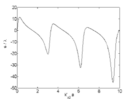
A typical dependence of the lateral shift on the slab’s thickness is shown in Fig. (2), where the permittivity, permeability and refractive index of the slab are , and () at wavelength mm Parazzoli , is re-scaled by . In order to obtain large lateral shifts, a large incidence angle is chosen to be . Calculation under these conditions shows that the lateral shift is equal to mm () for mm and is even equal to mm () for mm. It is interesting to note that the oscillation of the lateral shift with respect to is closely related to the periodical occurrence of transmission resonance at .
Apart from the above-mentioned positivity of the lateral shift (2) of the transmitted beam, it has other interesting properties at transmission resonance that deserving being pointed out. When the transmission resonance occurs, the transmission probability expressed by
reaches unity. Thus the light beam is totally transmitted. In this case, the lateral shift becomes
| (6) |
which is negative and less than that is predicted by Snell’ law of refraction. Meanwhile, the derivative of with respect to the thickness of the slab is, at resonance,
| (7) |
When the condition (4) is satisfied, this derivative is more than zero. Therefore, we see that under this condition the absolute value of the lateral shift decreases with increasing thickness of the slab around resonance points, because the lateral shifts around resonance points are negative. In other words, the positive lateral shift depends anomalously on the thickness of the slab around resonance points.
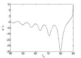
In addition, it is also indicated from Eq. (2) that the lateral shift depends not only on the thickness of the slab, but also on the angle of incidence and the refractive index . To see the latter more clearly, we draw in Fig. 3 the dependence of the lateral shift on the incident angle , where the thickness of the slab is , and all the other physical parameters are the same as Fig. 2. Fig. 3 shows that the lateral shift decreases with increasing the incidence angle . It is seen that the peaks of the lateral shift are approximately determined by . That is to say, the oscillation of the lateral shift with respect to the incidence angle also has close relation with the periodical occurrence of transmission resonances. Furthermore, when the incidence angle tends to , we have and . In this limit, the lateral shift takes the following form,
| (8) |
which approaches positive infinite. As is shown in Fig. 3, a strange phenomenon takes place here that for an enough large incidence angle (), the positive lateral shift becomes larger when increasing the incidence angle. Of course, the transmission probability in this limit tends to zero in the following way,
| (9) |
so that very few light beams can travel through the slab at this large positive lateral shift.
Now, let us have a brief look at the reflected beam. Denoted by the electric field of the corresponding plane wave component of the reflected beam, the reflection coefficient is determined by Maxwell’s equations and the boundary conditions to be
| (10) |
The factor that determines the phase of the reflection coefficient is
| (11) |
If we denote it by , then the phase of the reflection coefficient will be . Obviously, we have
It is meant by this equation that the local properties of with respect to are the same as those of . So the lateral shift of the reflected beam is locally given by Eq. (2) Steinberg ; Li-3 . Because , at resonance, , the reflect beam disappears, and its lateral shift has no definition in this case Li-2 . All these amount to a conclusion that when the resonant transmission doesn’t occur, the lateral shifts of the transmitted and reflected beam are the same in this symmetric configuration when measured in the same way.
Of course, when measured with reference to the prediction of Snell’s law, the lateral shift of the transmitted beam will be . Since the lateral shift is less than zero, when the lateral shift of the reflected beam is positive, the lateral shift of the transmitted beam is even positive with reference to the prediction of Snell’s law, especially at some large angles of incidence.
To show the validity of the above stationary-phase analysis, numerical calculations are performed, which confirm our theoretical results. In the numerical simulation, an incident Gaussian-shaped light beam is assumed, , which has the Fourier integral of the following form,
| (12) |
where , is the local waist of beam, and the amplitude angular-spectrum distribution is Gaussian, . Consequently, the electric field of the transmitted beam can be written as
| (13) |
The integral from to in Eq. (12) guarantees that the electric field of the incident beam has a perfect Gaussian profile with respect to . But for a real incident beam, the incidence angles of its angular-spectrum components extend from to . So the integral in the expression (13) in numerical simulations is performed from to ,
| (14) |
The numerically calculated lateral shift, , of the transmitted beam is defined as follows,
| (15) |
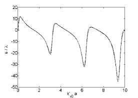
Calculations show that the stationary-phase approximation (2) for the lateral shift is in good agreement with the numerical result. In Fig. 4, we show such comparisons between the theoretical and numerical results, where the local waist of the Gaussian-shaped beam is chosen to be , and all the other optical parameters are the same as Fig. 2. It is noted that the discrepancy between theoretical and numerical results is due to the distortion of the transmitted light beam, especially when the local waist of the light beam is narrow. The further numerical simulations show that the wider the local waist of the incident beam is, the less the transmitted beam is distorted, and the closer to the theoretical result the numerical result is.
As pointed out in Ref. Huang , for an incident light beam of the angle spreading , the corresponding spreading of should be much smaller than , the period of , in order that the stationary-phase approach is valid. This leads to the following restriction to the thickness of the left-handed slab,
| (16) |
where is the wavelength of the light. With the angle spreading for a Gaussian-shaped light beam, we get
| (17) |
For instance, if the physical parameters are chosen to be , and (corresponding to the beam divergence of ), the requirement (17) is calculated to be . Clearly, this is compatible to the aforementioned requirement that the slab’s thickness should be of the order of the wavelength, . In addition, it is shown in Fig. 3 that the angular distance between two adjacent peaks is determined by , which gives . In order to retain the Gaussian-shaped beam’s profile in the traveling, the angular distance should be much smaller than the divergence of the beam, . As a reslut, the restriction (17) is also required to be satisfied. In a word, within this restriction the light beam can travel through the left-handed slab with negligible distortion, thus the stationary-phase approach in this problem is of validity.
IV Explanation of the lateral shift and Boundary effects
The previously discovered lateral shift of the transmitted beam through a slab of LHM is negative, when the permittivity and permeability are chosen to be and Kong-2 . On the basis of this result, the authors suggested that the lateral shift is always negative when the medium of the slab is left-handed material. How do we understand the present positive lateral shift? To this end, we rewrite the lateral shift (2) as,
| (18) |
which consists of two parts. One is a thickness-proportional term multiplied by a periodical factor with respect to , which is always negative for . The other itself is periodical. From the lateral shift (18), we see that it is the second term that makes the lateral shift to be positive. By averaging the two periodical functions over in one period , we obtain
| (19) |
which is always negative. This is exactly what we expect from Snell’s law of refraction. This may be explained as follows.
The negative refraction is inferred from the geometrical optics at a single interface between the “normal” and left-handed material, which has been demonstrated in the experiment Shelby . Moreover, the negative Goos-Hänchen shift for the totally reflected beam results from the interaction of the beam with the single interface of the LHM Berman ; Lakhtakia . When the light beam is incident on the left-handed slab at an enough large angle of incidence, the multiply reflection of the light beam takes place easily at the slab’s two interfaces with the air. This structure is often analogous to a Fabry-Perot optical interferometer Born : The two interfaces of the slab with the air play the role of partially transparent mirrors through which the light is coupled into and out of a resonant cavity. Here the periodical functions in Eq. (18) can be considered as the result of the interaction of the boundary effects of the slab’s two interfaces, which contribute to the lateral shift. The averaging over just effaces the interaction, so as to find the geometrical optic prediction. Actually, the positive lateral shifts presented here can be understood from the physical viewpoint on the reshaping process of the light beam by the interference of the multi-reflected beam in the slab.
When the parameters of the left-handed slab are chosen to be and Kong-2 , the negative lateral shift can also be understood by the boundary effects. In this case, the left-handed medium is a perfect match to the free space and the interfaces show no reflection, so that each plane wave component of the light beam can totally travel through the left-handed slab. Therefore, the lateral shift of the transmitted beam without reshaping is always negative. Mathematically, we can know from the Eq. (18) that the factors and are equal to zero for and , so that the periodical functions resulting from the interaction of the boundary effects don’t act on the lateral shift. Therefore, the opinion that the lateral shifts are always negative when a light beam travels through a left-handed slab with and is not qualified as generality. From all these discussions, the lateral shifts of the transmitted beam through a slab of LHM can be negative as well as positive, when the permittivity and the permeability are both negative.
V conclusion
To summarize, we have investigated that the lateral shift of the transmitted beam though a slab of left-handed medium can be negative as well as positive by the stationary-phase approach. A necessary condition (5) is put forward for the lateral shift to be positive, which is a restriction to the angle of incidence. The relation of the lateral shift with its anomalous dependence on the thickness of the slab around resonances points is discussed. The lateral shift also depends on the incidence angle and the negative refractive index. It is shown that the lateral shift of the reflected beam is equal to that of the transmitted beam when they are all measured from the normal to the interface (the axis) at which the incidence point is located. In order to demonstrate the validity of the stationary-phase approach, numerical simulations are made for a Gaussian-shaped beam. A restriction to the thickness of the slab is obtained that is necessary for the beam to retain its profile in the traveling. The positivity of the lateral shift can be explained in terms of the interaction of the boundary effects of the two slab’s interfaces with the air. Of course, the energy is conserved and the energy flow can be discussed by the approaches of Lai et al. Lai and J.A. Kong et al. Kong-2 . Finally, it should be noted that the possibility of observing the positive lateral shift of the transmitted beam through an ideal, lossless and nondispersive slab of LHM presented here remains an open question. However, with the advance of left-handed materials, we think, the lateral shifts may have potential applications not only in the measurements of the physical parameters of this material but also in optical modulations.
Acknowledgments
The authors are indebted to Professor V.G. Veselago for providing his papers. This work was supported in part by the National Natural Science Foundation of China (Grant No. 60377025), the Science Foundation of Shanghai Municipal Commission of Education (Grant No. 01SG46), the Science Foundation of Shanghai Municipal Commission of Science and Technology (Grant No. 03QMH1405), and by the Shanghai Leading Academic Discipline Program.
References
- (1) D.R. Smith, W.J. Padilla, D.C. Vier, S.C. Nemat-Nasser and S. Schultz, Phys. Rev. Lett. 84, 4184 (2000).
- (2) D.R. Smith and N. Kroll, Phys. Rev. Lett. 85, 2933 (2000).
- (3) R.A. Shelby, D.R. Smith and S. Schultz, Science 292, 77 (2001).
- (4) R.W. Ziolkowski and E. Heyman, Phys. Rev. E 64, 056625 (2001).
- (5) C.G. Parazzoli, R.B. Greegor, K. Li, B.E.C. Koltenbah and M. Tanielian, Phys. Rev. Lett. 90, 107401 (2003).
- (6) J.B. Pendry, Phys. Rev. Lett. 85, 3966 (2000).
- (7) G.W. ’tHooft, Phys. Rev. Lett. 87, 249701 (2001).
- (8) J.M. Williams, Phys. Rev. Lett. 87, 249703 (2001).
- (9) P.M. Valanju, R.M. Walser, and A.P. Valanju, Phys. Rev. Lett. 88, 187401 (2002).
- (10) N. Garcia and M. Nieto-Vesperinas, Phys. Rev. Lett. 88, 207403 (2002).
- (11) V.G. Veselago, Sov. Phys. Usp. 10, 509 (1968).
- (12) Z.M. Zhang and C.J. Fu, Appl. Phys. Lett. 80, 1097 (2002).
- (13) Z. Liu, L.-B. Hu and Z.-F. Lin, Phys. Lett. A 308, 294 (2003).
- (14) M. Notomi, Phys. Rev. B 62, 10696 (2000).
- (15) S. Foteinopoulou and C.M. Soukoulis, Phys. Rev. B 67, 235107 (2003).
- (16) F. Goos and H. Hänchen, Ann. Physik 1, 333 (1947).
- (17) P.R. Berman, Phys. Rev. E 66, 067603 (2002).
- (18) A. Lakhtakia, Electromagnetics, 23, 71 (2003).
- (19) I.V. Shadrivov, A.A Zharov and Y.S. Kivshar, Appl. Phys. Lett. 83, 2713 (2003).
- (20) J.A. Kong, B.-L. Wu and Y. Zhang, Appl. Phys. Lett. 80, 2084 (2002).
- (21) J.A. Kong, B.-L. Wu and Y. Zhang, Microw. Opt. Techn. Lett. 33, 136 (2002).
- (22) C.-F. Li and Q. Wang, Phys. Lett. A 275, 287 (2000).
- (23) X.-H. Huang and C.-F. Li, Europhys. Lett. 63, 28 (2003).
- (24) C.-F. Li, Phys. Rev. Lett. 91, 133903 (2003).
- (25) K. Artmann, Ann. Physik, 2, 87 (1948).
- (26) E.P. Wigner, Phys. Rev. 98, 145 (1955).
- (27) A.M. Steinberg and R.Y. Chiao, Phys. Rev. A 49, 3283 (1994).
- (28) C.-F. Li, Phys. Rev. A 65, 066101 (2002).
- (29) H.M. Lai, C.W. Kwok, Y.W. Loo and B.Y. Xu, Phys. Rev. E 62, 7330 (2000).
- (30) M. Born and E. Wolf, Principles of Optics (Pergamon Press, Oxford, 1980), Chap. 7, p.323.