Theoretical and Experimental Study of Stimulated and Cascaded Raman Scattering in Ultra-high-Q Optical Microcavities
Abstract
Stimulated Raman scattering (SRS) in ultra-high-Q surface-tension-induced spherical and chip-based toroid microcavities is considered both theoretically and experimentally. These microcavities are fabricated from silica, exhibit small mode volume (typically 1000 ) and possess whispering-gallery type modes with long photon storage times (in the range of 100 ns), significantly reducing the threshold for stimulated nonlinear optical phenomena. Oscillation threshold levels of less than 100 -Watts of launched fiber pump power, in microcavities with quality factors of 100 million are observed. Using a steady state analysis of the coupled-mode equations for the pump and Raman whispering-gallery modes, the threshold, efficiencies and cascading properties of SRS in UHQ devices are derived. The results are experimentally confirmed in the telecommunication band (1550nm) using tapered optical fibers as highly efficient waveguide coupling elements for both pumping and signal extraction. The device performance dependence on coupling, quality factor and modal volume are measured and found to be in good agreement with theory. This includes analysis of the threshold and efficiency for cascaded Raman scattering. The side-by-side study of nonlinear oscillation in both spherical microcavities and toroid microcavities on-a-chip also allows for comparison of their properties. In addition to the benefits of a wafer-scale geometry, including integration with optical, electrical or mechanical functionality, microtoroids on-a-chip exhibit single mode Raman oscillation over a wide range of pump powers.
I
introduction
Ultra-high-Q ( UHQ) surface-tension-induced microcavities (which we subsequently refer to as STIMs) combine small modal volume with some of the highest optical quality-factors (Q) to date of nearly 10 billion VernooyQ , and are of interest for a variety of studies ranging from fundamental physics such as cavity quantum electrodynamics VernooyQED KimbleScripta HarocheQED to applied areas such as low threshold and narrow linewidth lasers Sandoghdar CaiOL YangAPL , nonlinear optical oscillatorsChangBook HydrogenSRSreference , as well as high-sensitivity transducers for biochemical sensingVollmer . These silica microcavities feature whispering gallery type modes (WGMs) and rely upon exquisite smoothness at the cavity dielectric boundary to attain ultra-high-Q performance that is typically in excess of 100 million. For nonlinear optical studies, strong resonant buildup of energy in microscale volumes significantly reduces the threshold for nonlinear optical effects to occur. This was recognized in the pioneering work of Chang ChangScience ChangJOSA and Campillo CampilloNLO CampilloQED CampilloOptComm who observed and studied a variety of nonlinear optical effects in ultra-high-Q liquid microdoplets. Their work used free-space illumination to optically pump the microdroplets and thereby induce Raman oscillation ChangJOSA CampilloNLO CampilloOptComm , cascaded Raman scattering ChangJOSA and Brillouin scatteringChangBrillouin . Silica UHQ STIMs provide a far more stable and robust microcavity in comparison with liquid microdroplets. However, despite numerous studies on these devices over the past decade Braginsky Braunstein Collot Treussart GorodetskyOptComm GorodetskyOL GorodetskyJOSA1 GorodetskyJOSA2 IlchenkoCoupling IlchenkoMicrotorus the observation of nonlinear phenomena (beyond thermal effects) in these devices, had been limited to one report on Kerr-induced wavelength shifts at low temperatures Treussart . The advent of pumping and signal collection using fiber taper coupling methods Knight SpillanePRL CaiPTL CaiPRL proved an important turning point in access to nonlinear phenomena in this important micro-cavity system. Fiber tapers provide remarkably efficient coupling to and from the UHQ silica sphere system SpillanePRL CaiPRL and enable direct access to the technologically important optical fiber transport medium. The measured fiber-coupled threshold for a variety of nonlinear phenomena in taper-coupled, silica microspheres are lower than for any other nonlinear oscillator reported to date. Silica microsphere Raman lasers with ultra-low threshold levels of only 62 -Watts SpillaneNature have been demonstrated. Compared to microdroplets these devices allow stable and long term observation of nonlinear optical effects in microcavities. Cascaded Raman lasing in these devices of up to 5 orders has also been observed Min . The tapered optical fiber in these experiments functions to both pump WGMs as well as to extract the nonlinear Raman fields. In addition, the tapered-fiber coupling junction is highly idealSpillanePRL , making it possible to strongly overcouple ultra-high-Q cavities with negligible junction loss. This feature allows for the observation of very high internal differential photon conversion efficiencies approaching unity. Whereas microspheres are both compact and efficient nonlinear oscillators, their fabrication properties lack the control and parallelism typical of microfabrication techniques. Recently-developed ultra-high-Q toroid microcavities on-a-chip Armani provide a UHQ silica device with performance equivalent to a microsphere. UHQ toroids have several advantages over spheres including being wafer-scale devices that can be fabricated in parallel as dense arrays or integrated with electronics or other optical functionality. In this paper, we demonstrate and analyze nonlinear Raman oscillation in both microsphere and microtoroid on-a-chip structures. In addition to studying Raman oscillation in microcavities in detail, this work allows us to compare the performance and properties of toroidal and spherical microcavities. In addition to their fabrication and integration advantages, it will be seen that microtoroids also have performance advantages in comparison to microspheres. This includes a reduced number of supported azimuthal modes, which allows observation of single-mode Raman oscillation over a large range of pump powersKippenbergOLRaman (of critical importance in practical applications), as well lower Raman threshold due to a reduced mode volume compared to a spherical cavity.
The paper is organized as follows. The first section will give a brief introduction into the fabrication, coupling and optical properties of ultra-high-Q toroid on-a-chip and spherical microcavities. The second section will present a model for Raman lasing in a waveguide-coupled whispering-gallery-mode resonator. There, we derive the expression for the threshold and the efficiency of the conversion process. In the ultra-high-Q regime resonances are easily split into doublets due to intermode coupling of the degenerate clockwise and counterclockwise propagating whispering gallery modesWeiss . The effect of this intermode coupling on stimulated Raman scattering is also considered in this section. The case of cascaded Raman oscillation in which Raman signals serve to pump and generate higher-order Raman waves is also treated in the section. In the fourth section, the theoretical results are compared with experimental studies of the dependence of Raman threshold on quality-factor, mode volume and waveguide loading. Experimental results concerning power and efficiency during cascaded operation are presented and compared to theory and found to be in good agreement with theoretical predictions. Finally, a comparison of microtoroid oscillation properties with those of microspheres is presented in the fifth section.
II Ultra-high-Q surface-tension-induced microcavities
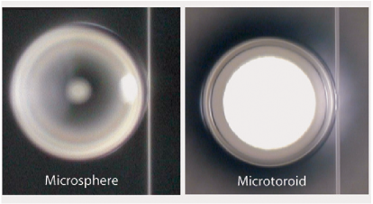
Surface-tension-induced microcavities such as micro-droplets, exhibit a superb, cavity surface finish (typically nanometer surface roughnessVernooyQ ) leading to whispering gallery type modes with some of the highest optical quality factors recorded to date. In the work presented here, both spherical and toroid microcavities on-a-chip made from silica are investigated. Both types of structures exhibit Q-factors in excess of 100 million. Briefly, the fabrication of both micro-sphere and micro-toroids relies upon surface tension to induce collapse of a given silica preform into the final cavity shape. Because the cavity fabrication involves a temporary liquid state the surface finish of the final ”solid” microcavity is excellent. In the case of a microsphere, the preform used here is an optical fiber tip which is heated and melted with a carbon-dioxide laser (10.6 wavelength). Surface tension causes the silica fiber tip to contract and form a spherical microcavity, while the remainder of the fiber stem serves as a holder for sphere-positioning. Light within the sphere is confined near an equatorial plane by continuous total internal reflection at the cavity interface. Microtoroids, on the other hand, use wafer microfabrication techniques involving a combination of lithography and etching combined with a final selective reflow process using a CO2 laser. The details of this fabrication process are reported in reference Armani . In the case of toroid microcavities the preform consists of a microfabricated silica disk supported by a silicon pillar. Illumination of the disk using a CO2 laser induces selective reflow of the silica. Surface tension causes the disk preform to collapse into a toroidal periphery, thereby creating the resonant cavity. Figure 1 contains an optical micrograph of a microsphere and a microtoroid on-a-chip.
Highly efficient evanescent coupling to these micro-cavities can be achieved by use of tapered optical fibers CaiPRL SpillanePRL , which are fabricated by melting and adiabatically tapering a standard, telecommunication fiber until a waist diameter of approximately 1 to 2 microns is reached. When brought into proximity of the WGM resonator and when the taper waist diameter is chosen to phase match to the WGMs, efficient coupling both to and from the microcavity can be achieved. Coupling can be described by the normalized coupling parameter which describes the ratio of intrinsic resonator lifetime to the external (coupling related) lifetime . Following the standard conventionsHaus , undercoupling is denoted by , overcoupling by , and critical coupling (the point of vanishing waveguide transmission) is denoted by The ability to achieve strong overcoupling is important as it exemplifies the very ideal natureSpillanePRL of the taper-microcavity, coupling junction. In addition to efficient excitation and extraction of optical power, the fiber taper provides direct coupling to optical fiber, thereby further facilitating laboratory measurements. In the case of microtoroids on-a-chip the taper is also crucial as a means of ”probing” the whispering gallery devices which are within a few microns of the silicon wafer surface.
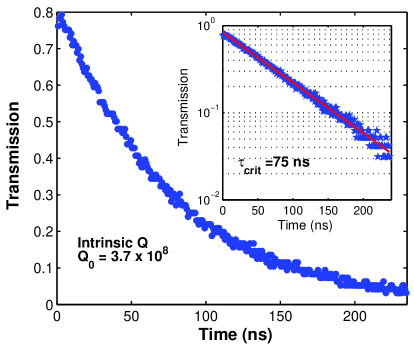
Using tapered optical fibers, resonator quality factor can be inferred from either linewidth measurements or cavity ringdown experimentsArmani . Figure 2 shows a cavity ringdown measurement on a 45--diameter microtoroid at 1550 nm, exhibiting a critically coupled Q of . In this measurement the WGM was excited on resonance, and the fiber-taper adjusted to the critical point. The cavity lifetime can then be inferred by gating-off the excitation laser, and recording the cavity decay signal. The critically coupled Q (including the waveguide coupling contributions) was 100 million, and when correcting the Q for the waveguide loading, as described in section III.B, an intrinsic quality factor of is inferred.
III Theoretical analysis of Raman Scattering in high-Q microcavites
III.1 1st Order Raman Scattering in microcavities
Raman scattering in a waveguide coupled microcavity can be described classically by using coupled mode equations for the pump and Raman fields with nonlinear Raman coupling terms. Other nonlinear effects, which can compete with Raman scattering, such as Four-wave-mixing or Brillouin scattering are not considered in this analysis as the microcavity poses stringent frequency matching constraints on these processes making their observation difficult. In the case of Stimulated Brillouin Scattering, the narrow gain bandwidth in the range of 100 MHZ, makes overlap of cavity modes with the Brillouin gain spectrum unlikely and was not observed in this work. In the case of parametric oscillation mediated by the Kerr-nonlinearity (i.e. four-wave mixing), energy conservation requires a triple resonance condition for signal, idler and pump mode, which can be satisfied only under certain conditionsKippenbergPRL . These additional constraints for oscillation based on the Kerr nonlinearity or Brillouin gain, cause stimulated Raman scattering - which is intrinsically phase-matched- to be the dominant microcavity nonlinear optical effect. For simplification, we assume that the pump wavelength and the Raman wave are on resonance and use the slowly varying envelope approximation.
| (1) |
Here signifies the slowly-varying amplitude of the pump and Raman WGM modes of the cavity and denotes the input wave. The excitation frequency of the pump mode and resonant Raman mode is given by and and is the total lifetime of photons in the resonator, which is related to the quality factor by . The coupling coefficient denotes the coupling of the input pump wave to the cavity whispering-gallery-mode . The relation associates the coupling coefficient with a corresponding lifetime, such that Haus . Since the Raman effect will excite both eigenmodes of the cavity (co- and counter-directionally propagating modes), equal amplitude emission occurs along both waveguide directions given by . The Raman intra-cavity gain coefficient is denoted as , which can be related to the more commonly used gain coefficient (measured in units of m/Watt) by,
| (2) |
where is the effective modal volume Boyd , and is the electric field vector VernooyQED . The effective mode volume accounts for the intensity dependent gain, and for silica microspheres and microtoroids has approximately twice the value than the energy related definition of mode volume. Steady state analysis of the coupled mode equations, results in a clamped, cavity, pump field above threshold. This clamping alters the coupling of pump power to the resonator, and, in turn, the pump power dependence of Raman laser power such that the following square root dependence results.
| (3) |
The physical origin of this square root dependence of the pump-to-Raman conversion can be viewed as a “pumping inefficiency” i.e. the coupled pump power does not increase linearly with launched fiber power. The nonlinear dependence of coupled pump power can be illustrated by considering a pump wave that is initially critically coupled to the resonator. As noted above, critical coupling features complete transfer and dissipation of power from the resonator (i.e., zero transmission). In terms of the fields involved in coupling both to and from the resonator, critical coupling results from the destructive interference of the cavity leakage field with the transmitted, pump field (i.e., the portion that does not couple to the resonator from the waveguide). Once the onset of Raman lasing is reached, the cavity pump field is clamped at the threshold value resulting in a fixed cavity pump leakage field. Subsequent increase in launched pump power will imbalance the leakage and the transmitted pump fields, giving rise to finite transmission and a shift away from the critical point. The pump coupling to the resonator is thereby less and less efficient as the pump field is increased. The expression for the Raman threshold pump power can be factorized into terms involving modal volume, waveguide-cavity coupling strength and cavity lifetime (or Quality factor). To facilitate separation of the coupling and intrinsic lifetime dependence, we use the dimensionless normalized coupling parameter . In the ideal case of a single-mode waveguide coupled to a whispering-gallery-mode the waveguide transmission as a function of coupling is given by and typically varies exponentially with the waveguide-microcavity ”coupling gap” distance Haus . Using these definitions and under the assumption of equal coupling properties and photon lifetimes for both the pump and Raman mode, i.e. and ,the threshold expression is given by:
| (4) |
Here we have also introduced which is a possible correction factor to account for intermode coupling of the degenerate clockwise and counterclockwise propagating whispering-gallery modes. This factor will be explained in the next section. The threshold expression follows an inverse square dependence on the quality factor. This reflects the fact that an increase in Q will cause a twofold benefit in terms of both reducing cavity round trip losses that must be overcome for threshold as well as increasing the Raman gain, due to the intensity dependence of the Raman gain coefficient on the pump field. In addition, the equation shows that the threshold scales linearly with the modal volume. Both the coupling and mode volume dependence of the Raman threshold are examined experimentally in the next section. When analyzing the coupling dependence under the assumption of equal Raman and pump quality factors and coupling factors, the minimum threshold occurs when or , i.e. in the undercoupled regime with finite waveguide transmission of . This minimum pump threshold is given by,
| (5) |
It is worth noting that at this coupling condition, the circulating pump-power in the resonator is not maximum. This can be understood since minimum threshold represents an optimal balance of both pump coupling and Raman mode coupling loss. The conversion of pump power to Raman power above threshold can be characterized by the differential slope efficiency. The bidirectional external differential slope efficiency is derived by linearizing the expression for near the threshold condition and is given by,
| (6) |
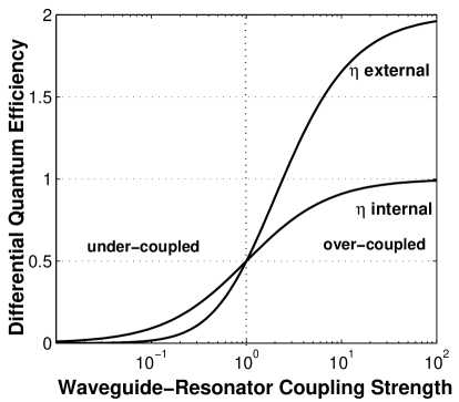
Figure 3 shows the differential slope efficiency as a function of coupling strength. It is noteworthy that it approaches the value of in the limit of strong overcoupling . Surprisingly, this value exceeds unity, indicating that every waveguide pump photon added above threshold, is converted to more than one Raman photon. This result can be understood by again considering the nonlinear dependence of coupled pump power, except this time in the over-coupled regime. In particular, the differential increase in coupled pump power grows more quickly in the overcoupled (more slowly in the undercoupled regime) than the differential increase in launched pump power. This leads to the interesting effect that the differential photon conversion efficiency can exceed unity. Taking into account the nonlinear dependence of coupled pump power by defining the internal differential efficiency as the coupled (as distinct from the launched) pump-to-Raman power, the efficiency approaches, as expected , the value in the limit of strong overcoupling.
| (7) |
Figure 3 shows both the internal and external differential Raman conversion efficiencies as a function of coupling strength.
III.2 The effect of intermode coupling on stimulated Raman scattering
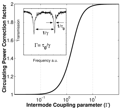
In the ultra-high-Q regime, resonances of a whispering-gallery-type microcavity are often split into doubletsBraginsky Weiss . This splitting is due to coupling of the degenerate clockwise and counterclockwise propagating modes by either intrinsic or surface scattering centers. The modified coupling properties have been extensively studied KippenbergOL . Here we briefly summarize the results of this study and analyze the effect of intermode coupling on Raman scattering. The extent to which intermode coupling modifies the waveguide coupling properties can be described by the dimensionless intermode coupling parameter , where is the rate of coupling of the degenerate clockwise and counterclockwise modes. It is easily measured as the linewidth normalized splitting in the undercoupled regime (see figure 4 inset). The presence of intermode coupling has several consequences. First, the critical point (as defined by vanishing waveguide transmission) is shifted towards a coupling point, which, using the conventional coupling terminology, is considered overcoupled as The point of vanishing transmission occurs at:
| (8) |
Second, the shifted critical point is accompanied by a maximum reflection into the backwards direction of the waveguide (i.e. the contra-directional waveguide mode). The magnitude of the reflection at the above modified critical point is given by
| (9) |
Third, the leakage of the cavity field into the backwards waveguide direction causes a reduction of the cavity buildup factor with respect to the ideal case in the absence of intermode coupling. In the limit of strong modal coupling, the cavity buildup factor is reduced by a factor of , which subsequently causes a twofold increase in the threshold necessary to achieve Raman lasing. Figure 4 shows the circulating power correction factor as a function of the dimensionless intermode coupling parameter In the presence of modal coupling the waveguide coupling condition for minimum threshold experiences a slight shift towards overcoupling with the maximum shift occurring at . In the regime of very strong modal coupling the condition of minimum Raman threshold approaches again the original condition .
III.3 Analysis of Cascaded Raman Scattering in high-Q microcavities
The first Raman field can itself act as a secondary pump field and generate further Raman modes. This process of cascaded Raman scattering can be described by including higher order coupling terms into the coupled mode equations of pump and Raman fields as shown belowMin .
| (10) | |||||
where is the Raman order. To find the corresponding thresholds and output powers for these higher order processes, the set of equations can be solved iteratively in steady state. Here, we have introduced the dimensionless coefficients .
| (11) |
The general solutions for the threshold of the even and odd order Raman modes are given by the following expressions. As in the previous section, we have assumed equal coupling strengths and intrinsic Q factors for the pump and Raman modes.
| (12) |
As evident from these expressions even and odd order stokes fields exhibit different threshold powers as a function of stokes order (N). When considering Raman scattering in silica at optical frequencies, one can approximate the above expressions by taking since the Raman shift is small compared to the optical frequency. In addition it is assumed that the mode volume is wavelength independent. Under this assumption, the threshold expressions reduce to:
| (13) | |||||
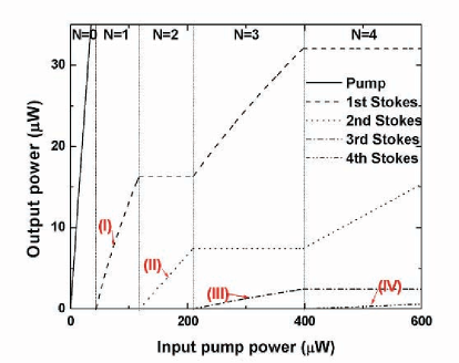
It follows that the threshold for cascaded Raman oscillation exhibits a dependence on Raman order N. The emission power dependences vary depending upon whether the highest order wave is even or odd. For the odd order case, all odd orders increase as the square root of the pump power and even orders are clamped. For the even order case, all even order lines increase linearly with pump power while odd orders are clamped. Figure 5 illustrates this behavior showing the Raman output for several stokes orders as a function of input pump power. The analytic expressions for the Raman output power in these cases are given by:
| (14) | |||||
The differential power conversion efficiencies can be obtained by linearizing the above expressions near the threshold condition. The external and internal differential efficiencies decrease steadily as a function of stokes order (). For optical frequencies that are much larger than the Raman shift, the external differential conversion efficiency reduces to:
| (15) | |||||
For high order (N) Raman fields, the external differential conversion efficiency thus follows a -dependence.
IV Experimental study of Stimulated Raman Scattering in ultra-high-Q microspheres
We have observed stimulated Raman scattering using fiber-taper-coupled, ultra-high-Q, surface-tension-induced silica microspheres. Tapered optical fibers provide both a very efficient and practical means for pumping and laser signal extraction through the same fiber. The experimental setup in this study is identical to the one reported earlierSpillaneNature and the tapered fiber was attached to a piezoelectric stage which allowed precise control of the taper-microcavity coupling gap (20 nm resolution) and variation of the waveguide-resonator coupling strength. The Q-factors obtained in the microspheres were typically in the range of and taper insertion loss (fiber to fiber) was usually less than 5%.
To excite the UHQ modes, we used a narrow-linewidth, external-cavity laser emitting in the 1550 nm band. In the case of microspheres, the WGM field spatial forms are known analytically and characterized by the radial, angular, azimuthal and polarization mode number . Due to fabrication-induced eccentricity, the -fold-degeneracy of the azimuthal modes is lifted yielding a complex mode spectrum. For the spheres considered in this work the eccentricity-induced splitting was in the range of several GigaHertz. Microtoroids on-a-chip, on the other hand, possess a significantly reduced mode spectrum due to the strong azimuthal modal confinement provided by the toroid geometry. This both simplifies their spectra and enables operation of microtoroid-Raman lasers in the desirable single mode regime, which is of significant practical importance.
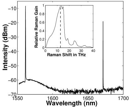
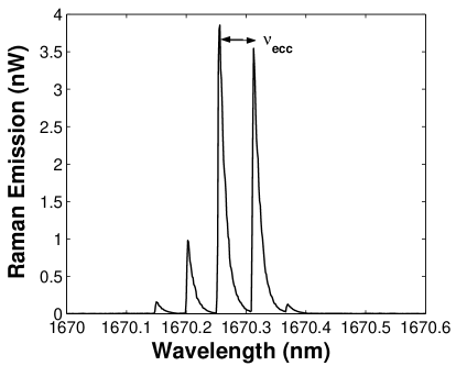
Stimulated Raman oscillation was observed by pumping a single WGM and monitoring the transmission using an optical spectrum analyzer. Once the threshold for SRS was exceeded, lasing modes in the 1650-nm band could be observed, in correspondence with the peak Raman gain which occurs downshifted in frequency by approximately 14 THz relative to the pump frequency (wavelength shift of approximately 110 nm). Figure 6 shows Raman emission for an ultra-high-Q microsphere. The Raman emission with respect to the gain peak is provided in the inset of figure 6. Since the fundamental whispering gallery modes are most tightly confined (i.e., smallest mode volume), Raman lasing is expected to occur first for these modes. The presence of nearly degenerate azimuthal modes in a spherical microcavity (i.e., weak eccentricity splitting), causes simultaneous oscillation on several azimuthal modes. Figure 7 shows a higher resolution spectral scan of the spectrum in figure 6. Several azimuthal modes can be observed to be oscillating simultaneously.
The threshold formula predicts a strong dependence of the Raman threshold on waveguide coupling. Figure 8 shows the measured Raman threshold as a function of taper-microcavity gap distance for a fundamental WGM.
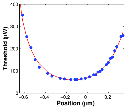
The solid line is a fit using the theoretical results from the first section (equation 3) and assuming equal pump and Raman Q factors and coupling conditions. The minimum threshold does indeed occur undercoupled with finite taper transmission at in good agreement with the theoretically predicted value of .
As a further verification of the threshold formula we compared the theoretical minimum threshold value with the observed value. The quality factor and the mode splitting of the whispering-gallery mode were measured by performing a linewidth sweep in the undercoupled regime, where the backscattering-induced doublet structure is most pronounced. These measurements yielded and . The size of the microsphere was inferred from the free spectral range, i.e. diameter, where the free-spectral range denotes here modes with successive angular mode number . The mode volume was calculated using analytic expressions based on estimated mode numbers for the fundamental WGM . CalculationsBuck LittleHaus yielded a modal volume of ca. . The overlap factor for pump and Raman mode is assumed to be unity. Using these values, the theoretically expected minimum threshold is given by which is in good agreement with the experimentally measured value of 62
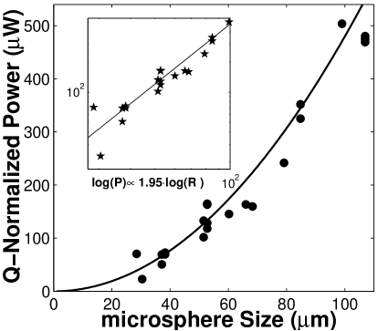
The dependence of the Raman threshold on the modal volume was also investigated. For this measurement the Raman threshold was measured for micro-sphere resonators having varying diameters in the range of ca. 25-120 . (For diameters smaller than 25- thermally induced wavelength shifts lead to pumping instabilities.) In this diameter range, the mode volume follows an approximately quadratic dependence (actual inferred exponent is LittleHaus Buck ) on the sphere radius. As an aside, for smaller spheres the mode volume deviates from this behavior and ultimately, for very small diameters, the mode volume increases due to weakening of the whispering gallery confinementBuck . The minimum mode volume occurs for a radius of (for )Buck for 1550 nm wavelength and the mode volume is . However, this size is not optimum for stimulated Raman scattering as the additional benefit of reduced mode volume is more than offset by the significant decrease in Q factor to LittleHaus (Threshold power ). For small mode volumes, it has been predicted that the gain coefficient can exhibit a dependence on mode volume due to cavity QED effectsCampilloQED . However, in the case of stimulated Raman Scattering in silica microspheres these effects are not expected to be observable Matsko and an approximately quadratic relationship due to the mode volume is predicted.
Figure 9 shows the experimental results for threshold versus microsphere diameter. In this experiment, the minimum Raman threshold , the microsphere size (as inferred from the free-spectral-range), the intrinsic Q in the pump band () and the intermode coupling parameter () were measured. To extract the volumetric dependence of the Raman threshold using data from cavities having different resonant characteristics, the threshold data were normalized to the set of parameters . The result of this procedure is shown in figure 9. The data indeed show a quadratic dependence on R (the actual fitted exponential from a double logarithmic plot is 1.95 and is in good agreement with the expected value of 1.83) and confirm the linear relationship of the Raman threshold on the mode volume as predicted by equation 4.
IV.1 Cascaded Raman Scattering in ultra-high-Q microspheres
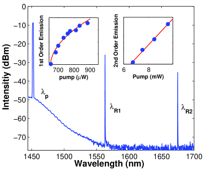
In addition to first order Raman scattering, we have also observed cascaded Raman scattering. Figure 10 shows a typical cascaded Raman spectrum, for a UHQ microcavity pumped at 1450 nm. The pump-to-Raman conversion characteristics for first order Raman scattering and the 2nd order Raman mode are shown in the inset. It can be seen that the first order mode does indeed exhibit a square-root dependence on the launched pump power. The solid line is a fit using equation 12. The higher order Raman mode exhibits the expected linear increase with pump power.
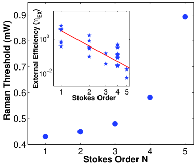
To study cascaded Raman scattering beyond 2nd order, experiments using a 980 nm wavelength pump Min were employed. The shorter wavelength pump allowed the observation of up-to 5th-order cascades (from 980-1300 nm) owing to the reduced mode volume at shorter wavelengths, and the higher Raman gain coefficient . With less than 900 -Watts of launched fiber power up to fifth order Stimulated Raman Scattering was observed Min , and the threshold and efficiency of the cascades measured. Figure 11 shows the Cascaded Raman threshold for a microsphere as a function of the order of the cascade, for fixed coupling condition. The solid line is a cubic fit (as predicted by equation 11), which yields good qualitative agreement with the experimentally measured thresholds. The inset of figure 11 shows a double logarithmic plot of the measured differential conversion efficiency of the cascaded Raman scattering process. The efficiency of the cascades decreases as a function of Stokes order, as is theoretically predicted by equation 13.
V Raman Scattering in Ultra-high-Q toroid microcavities on-a-chip.
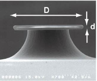
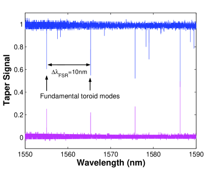
Toroid microcavities allow on-chip integration of ultra-high-Q performance with other optical, mechanical and electrical functionality. In addition the wafer-scale fabrication process allows precise dimensional control and parallelism. Figure 12 shows a scanning electron microscope of a toroid microcavity. In addition to the design freedom and control brought about by micro-fabrication and integration possibilities, toroid microcavities also exhibit significant advantages in terms of their Raman-emission properties. Whereas microsphere cavities show low threshold operation, their emission is inherently multi-mode due to the presence of azimuthal modes, as shown in figure 7 of the previous section. In contrast, toroid microcavities on-a-chip have a significantly reduced mode spectrum, such that single mode Raman lasing can be observed. The reduced number of azimuthal modes is due to the cavity geometry, which supports only a few modes in the azimuthal direction due to the toroidal confinementIlchenkoMicrotorus . Figure 13 shows the mode spectrum of a toroid microcavity. Only two higher order modes are present in the spectrum, and successive modes are separated by the free spectral range of the cavity, which in the figure is 10 nm. This is in contrast to a microsphere of identical principal diameter which would support azimuthal modes weakly split by eccentricity.
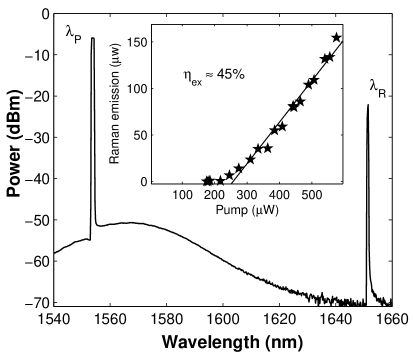
The suppression of azimuthal modes, has important consequences on the spectral emission properties of single and cascaded Raman scattering. Most notably, single transverse mode Raman oscillation can be observed over a large range of pump powers. Figure 14 shows a toroid microcavity Raman laser, which exhibits single mode oscillation at emission power levels up to 160 with high efficiency (45% at the critical point). The single-mode emission property is a significant advantage in practical applications of nonlinear optical oscillators.
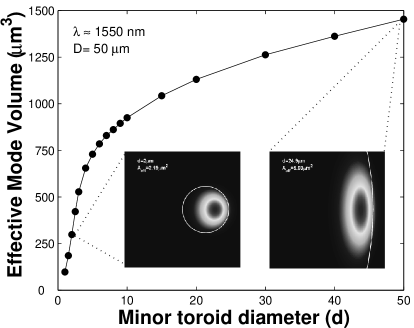
Toroidal and spherical microcavities having similar Q and outer diameter will differ in modal volume. Toroids, owing to the added transverse confinement will have a reduced mode volume and hence a lower Raman threshold. The degree to which the threshold is reduced will depend on the ”aspect ratio” of the toroid or D/d where D is the outer or principal diameter and d is the minor diameter (see figure 12). The modal volume of the fundamental toroid mode in a D= 50 toroid plotted versus is provided in figure 15. The calculation uses a finite element mode solver as there are no analytical expressions available for toroid mode volume. The case of d = 50 corresponds to a sphere. Overall, the toroidal mode volume can be seen to be lower than the sphere. There are also two distinct regimes of mode volume behavior. In the first, the mode volume reduces very slowly as d is reduced (). This regime features a weak lateral confinement very similar in nature to that of the sphere and related to the gentle transverse curvature of the toroidal dielectric boundary. In the second regime, the mode volume reduces very quickly as d is reduced. This regime is characterized by strong, lateral, index confinement resulting from the toroidal boundary being comparable in diameter to the mode field. The inset to this figure provides mode fields for the toroid in these two regimes to further illustrate this idea. It is clear that substantial reductions in threshold are possible using these devices. We are currently characterizing the reductions possible experimentally.
VI Summary
In summary we have experimentally and theoretically analyzed Raman oscillation in fiber-taper-coupled microspheres and microtoroids on-a-chip. A theoretical analysis was presented using the coupled mode equations for the pump and Raman WGMs. Using these equations, the threshold condition for stimulated Raman scattering was derived and the relative importance of waveguide coupling strength, mode volume and intrinsic resonator Q were described. These theoretical dependences were verified experimentally. Furthermore the analysis was extended to the case of cascaded Raman oscillation and threshold and efficiency expressions were derived for higher-order Raman fields. This analysis revealed that odd and even order Raman lines exhibit different pump-to-Raman emission characteristics. Even order Stokes fields are found to exhibit a linear increase in generated Raman power as a function of pump power, whereas odd-order Stokes fields exhibit a square root dependence. Analysis showed and experiment confirmed that the threshold for N-th-order cascaded Raman oscillation exhibits a cubic dependence on order and that the associated efficiency of the process scales inverse quadratically with order.
Microtoroids, in addition to having significant practical advantages with respect to their chip-based fabrication, have both spectral and power efficiency advantages in comparison to Raman oscillation in microspheres. Their stronger lateral confinement provides two distinct benefits. First, a drastic reduction in the complexity of the mode spectrum enabling single-mode oscillation in the microtoroid based device. Second, a controllable and reduced mode volume so that for comparable Q factors, microtoroid devices should have lower threshold pump powers. We are currently investigating the latter advantage experimentally.
The importance of fiber taper coupling in these measurements cannot be over emphasized. These inherently fiber-compatible waveguides provide exceptional coupling efficiencies to and from the ultra-high-Q devices. They are also indispensable in coupling to the microtoroid devices which reside near the surface of a silicon wafer. Using taper coupling, the lowest threshold observed in this study was 62 Watts of launched power, a value which is nearly 3-orders of magnitude lower than for free-space illumination of micro-droplets.
VII
Acknowledgement
This work was supported by the NSF, DARPA and the Caltech Lee Center for Advanced Networking.
References
- (1) D. W. Vernooy, V. S. Ilchenko, H. Mabuchi, E. W. Streed, and H. J. Kimble, “High-Q measurements of fused-silica microspheres in the near infrared,” Optics Letters, vol. 23, no. 4, pp. 247–249, 1998.
- (2) D. W. Vernooy, A. Furusawa, N. P. Georgiades, V. S. Ilchenko, and H. J. Kimble, “Cavity QED with high-Q whispering gallery modes,” Physical Review A, vol. 57, no. 4, pp. R2293–R2296, 1998.
- (3) H. J. Kimble, “Strong interactions of single atoms and photons in cavity qed,” Physica Scripta, vol. T76, pp. 127–137, 1998.
- (4) S. Haroche and D. Kleppner, “Cavity quantum electrodynamics,” Physics Today, vol. 42, no. 1, pp. 24–30, 1989.
- (5) V. Sandoghdar, F. Treussart, J. Hare, V. LefevreSeguin, J. M. Raimond, and S. Haroche, “Very low threshold whispering-gallery-mode microsphere laser,” Physical Review A, vol. 54, no. 3, pp. R1777–R1780, 1996.
- (6) M. Cai, O. Painter, K. J. Vahala, and P. C. Sercel, “Fiber-coupled microsphere laser,” Optics Letters, vol. 25, no. 19, pp. 1430–1432, 2000.
- (7) Y. Yang, D. K. Armani, and K. J. Vahala, “Fiber-coupled erbium microlasers on a chip,” Appl. Phys. Lett., vol. 83, p. 825, 2003.
- (8) R. Chang and A. J. Campillo, Optical processes in microcavities, vol. 3 of Advanced series in applied physics. Singapore: World Scientific, 1996.
- (9) S. Uetake, R. S. D. Sihombing, and K. Hakuta, “Stimulated raman scattering of a high-Q liquid-hydrogen droplet in the ultraviolet region,” Optics Letters, vol. 27, no. 6, pp. 421–423, 2002.
- (10) F. Vollmer, D. Braun, A. Libchaber, M. Khoshsima, I. Teraoka, and S. Arnold, “Protein detection by optical shift of a resonant microcavity,” Applied Physics Letters, vol. 80, no. 21, pp. 4057–4059, 2002.
- (11) S. X. Qian, J. B. Snow, H. M. Tzeng, and R. K. Chang, “Lasing droplets - highlighting the liquid-air interface by laser-emission,” Science, vol. 231, no. 4737, pp. 486–488, 1986.
- (12) J. Z. Zhang and R. K. Chang, “Generation and suppression of stimulated brillouin-scattering in single liquid droplets,” Journal of the Optical Society of America B-Optical Physics, vol. 6, no. 2, pp. 151–153, 1989.
- (13) H. B. Lin and A. J. Campillo, “Cw nonlinear optics in droplet microcavities displaying enhanced gain,” Physical Review Letters, vol. 73, no. 18, pp. 2440–2443, 1994.
- (14) A. J. Campillo, J. D. Eversole, and H. B. Lin, “Cavity quantum electrodynamic enhancement of stimulated- emission in microdroplets,” Physical Review Letters, vol. 67, no. 4, pp. 437–440, 1991.
- (15) H. B. Lin and A. J. Campillo, “Microcavity enhanced raman gain,” Optics Communications, vol. 133, no. 1-6, pp. 287–292, 1997.
- (16) J. Z. Zhang and R. K. Chang, “Generation and suppression of stimulated brillouin-scattering in single liquid droplets,” Journal of the Optical Society of America B-Optical Physics, vol. 6, no. 2, pp. 151–153, 1989.
- (17) V. B. Braginsky, M. L. Gorodetsky, and V. S. Ilchenko, “Quality-factor and nonlinear properties of optical whispering- gallery modes,” Physics Letters A, vol. 137, no. 7-8, pp. 393–397, 1989.
- (18) D. Braunstein, A. M. Khazanov, G. A. Koganov, and R. Shuker, “Lowering of threshold conditions for nonlinear effects in a microsphere,” Physical Review A, vol. 53, no. 5, pp. 3565–3572, 1996.
- (19) L. Collot, V. Lefevreseguin, M. Brune, J. M. Raimond, and S. Haroche, “Very high-Q whispering-gallery mode resonances observed on fused-silica microspheres,” Europhysics Letters, vol. 23, no. 5, pp. 327–334, 1993.
- (20) F. Treussart, V. S. Ilchenko, J. F. Roch, J. Hare, V. Lefevre-Seguin, J. M. Raimond, and S. Haroche, “Evidence for intrinsic kerr bistability of high-Q microsphere resonators in superfluid helium,” European Physical Journal D, vol. 1, no. 3, pp. 235–238, 1998.
- (21) M. L. Gorodetsky and V. S. Ilchenko, “High-Q optical whispering-gallery microresonators - precession approach for spherical mode analysis and emission patterns with prism couplers,” Optics Communications, vol. 113, no. 1-3, pp. 133–143, 1994.
- (22) M. L. Gorodetsky, A. A. Savchenkov, and V. S. Ilchenko, “Ultimate Q of optical microsphere resonators,” Optics Letters, vol. 21, no. 7, pp. 453–455, 1996.
- (23) M. L. Gorodetsky and V. S. Ilchenko, “Optical microsphere resonators: optimal coupling to high-Q whispering-gallery modes,” Journal of the Optical Society of America B-Optical Physics, vol. 16, no. 1, pp. 147–154, 1999.
- (24) M. L. Gorodetsky, A. D. Pryamikov, and V. S. Ilchenko, “Rayleigh scattering in high-Q microspheres,” Journal of the Optical Society of America B-Optical Physics, vol. 17, no. 6, pp. 1051–1057, 2000.
- (25) V. S. Ilchenko, M. L. Gorodetsky, and S. P. Vyatchanin, “Coupling and tunability of optical whispering-gallery modes - a basis for coordinate meter,” Optics Communications, vol. 107, no. 1-2, pp. 41–48, 1994.
- (26) V. S. Ilchenko, M. L. Gorodetsky, X. S. Yao, and L. Maleki, “Microtorus: a high-finesse microcavity with whispering-gallery modes,” Optics Letters, vol. 26, no. 5, pp. 256–258, 2001.
- (27) J. C. Knight, G. Cheung, F. Jacques, and T. A. Birks, “Phase-matched excitation of whispering-gallery-mode resonances by a fiber taper,” Optics Letters, vol. 22, no. 15, pp. 1129–1131, 1997.
- (28) S. M. Spillane, T. J. Kippenberg, O. J. Painter, and K. J. Vahala, “Ideality in a fiber-taper-coupled microresonator system for application to cavity quantum electrodynamics,” Physical Review Letters, vol. 91, no. 4, pp. art. no.–043902, 2003.
- (29) M. Cai, P. O. Hedekvist, A. Bhardwaj, and K. Vahala, “5-gbit/s ber performance on an all fiber-optic add/drop device based on a taper-resonator-taper structure,” Ieee Photonics Technology Letters, vol. 12, no. 9, pp. 1177–1179, 2000.
- (30) M. Cai, O. Painter, and K. J. Vahala, “Observation of critical coupling in a fiber taper to a silica- microsphere whispering-gallery mode system,” Physical Review Letters, vol. 85, no. 1, pp. 74–77, 2000.
- (31) S. M. Spillane, T. J. Kippenberg, and K. J. Vahala, “Ultralow-threshold raman laser using a spherical dielectric microcavity,” Nature, vol. 415, no. 6872, pp. 621–623, 2002.
- (32) B. Min, T. Kippenberg, and K. Vahala, “A compact, fiber-compatible cascaded raman laser,” Optics Letters, vol. 28, p. 17, 2003.
- (33) D. K. Armani, T. J. Kippenberg, S. M. Spillane, and K. J. Vahala, “Ultra-high-Q toroid microcavity on a chip,” Nature, vol. 421, no. 6926, pp. 925–928, 2003.
- (34) T. J. Kippenberg, S. M. Spillane, and K. J. Vahala, “Ultralow-threshold microcavity raman laser on a microelectronic chip,” Optics Letters, vol. 29, no. 11, pp. 1224–1226, 2004.
- (35) D. S. Weiss, V. Sandoghdar, J. Hare, V. Lefevreseguin, J. M. Raimond, and S. Haroche, “Splitting of high-Q mie modes induced by light backscattering in silica microspheres,” Optics Letters, vol. 20, no. 18, pp. 1835–1837, 1995.
- (36) H. A. Haus, Electromagnetic fields and energy. Englewood Cliff: Prentice Hall, 1989.
- (37) T. J. Kippenberg, S. M. Spillane, and K. J. Vahala, “Kerr-nonlinearity optical parametric oscillation in an ultra-high-Q toroid microcavity,” Physical Review Letters, no. accepted for publication, 2004.
- (38) R. Boyd, Nonlinear optics. Boston: Academic Press.
- (39) T. J. Kippenberg, S. M. Spillane, and K. J. Vahala, “Modal coupling in traveling-wave resonators,” Optics Letters, vol. 27, no. 19, pp. 1669–1671, 2002.
- (40) J. R. Buck and H. J. Kimble, “Optimal sizes of dielectric microspheres for cavity QED with strong coupling,” Physical Review A, vol. 67, no. 3, pp. art. no.–033806, 2003.
- (41) B. E. Little, J. P. Laine, and H. A. Haus, “Analytic theory of coupling from tapered fibers and half-blocks into microsphere resonators,” Journal of Lightwave Technology, vol. 17, no. 4, pp. 704–715, 1999.
- (42) A. B. Matsko, A. A. Savchenkov, R. J. Letargat, V. S. Ilchenko, and L. Maleki, “On cavity modification of stimulated raman scattering,” Journal of Optics B-Quantum and Semiclassical Optics, vol. 5, no. 3, pp. 272–278, 2003.