Long sandwich modules for photon veto detectors
Abstract
Long lead–scintillator sandwich modules developed for the BNL experiment KOPIO are described. The individual 4 m long module consists of 15 layers of 7 mm thick extruded scintillator and 15 layers of 1 mm lead absorber. Readout is implemented via WLS fibers glued into grooves in a scintillator with 7 mm spacing and viewed from both ends by the phototubes. Time resolution of 300 ps for cosmic MIPs was obtained. Light output stability monitored for 2 years shows no degradation beyond the measurement errors. A 4 m long C–bent sandwich module was also manufactured and tested.
pacs:
29.40.McI Introduction
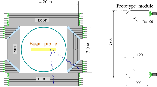
BNL experiment KOPIO e926 to study the rare kaon decay represents a significant experimental challenge. The most difficult mode to suppress is which can simulate if two of four photons are undetected. To suppress the dominant background from kaon decays a single photon veto capability must be up to an order of magnitude better than measured in previous experiments for low energy photons (below 50 MeV). High photon absorption efficiency is required to achieve a detection efficiency of better than 0.9998 for 100 MeV photons. High light yield over the entire detector volume is crucial to deal with photonuclear reactions that are likely to limit the achievable efficiency. Since the momentum of the in KOPIO is determined using a pulsed beam and time-of-flight method, the veto system must have good time resolution of about 200 ps for photon energies of 100–200 MeV while covering the full solid angle around the kaon decay region. The cost of the veto system is also a very important issue given the detector size of roughly m3. The scheme of the proposed experiment is shown in Fig. 1.

Lead–plastic scintillator sandwich veto counters are being considered for the barrel veto detector which must have a thickness of 17 (radiation lengths). To read out light from the long scintillators, a two–ended wavelength–shifting fiber readout technique will be used. The two-ended readout provides good timing as well as redundancy for failed channels. Similar detectors were used in the BNL experiment E787 e787 (without WLS fibers) and the KEK experiment E391 e391 . The extrusion method allows us to produce relatively cheap long grooved scintillators which are well matched to the WLS fiber readout.
II Sandwich module design
The results of tests of single extruded counters were reported in Ref. nim1 ; nim2 . The main results for extruded counters with WLS fiber readout are summarized in Table 1.
| Counter thickness | Spacing | Fiber type | Light yield | |
| mm | mm | p.e./MIP | ns | |
| 7 | 19 | multi–clad | 11.2 | |
| 7 | 10 | multi–clad | 19.6 | 0.85 |
| 7 | 10 | single–clad | 14.4 | 0.87 |
| 7 | 7 | multi–clad | 26.2 | 0.71 |
| 7 | 7 | single–clad | 20.8 | 0.76 |
| 3 | 10 | multi–clad | 8.5 | 0.92 |
| 7 (BC404) | 7 | multi–clad | 32 | 0.65 |
Although the light attenuation length of extruded polystyrene scintillator is about 30 cm, the one with WLS fiber readout produces 0.8 of the light yield of BC404 scintillator. Single–clad (s.c.) and multi–clad (m.c.) Bicron fibers provide practically the same time resolution. Instead of using a wrapping material for a reflector we applied a novel technique: the scintillator is etched by a chemical agent that results in the formation of a micropore deposit over the plastic surface, following which the diffuse film is fixed in a settling tank. The deposit thickness (30-100 m) depends on the etching time. An advantage of this approach over the commonly used white diffuse papers is the almost ideal contact of the reflector with the scintillator. Moreover, it provides the option of gluing a lead sheet to the plastic covered by the chemical reflector which facilitates assembling a sandwich unit. We tested a small size sandwich assembly of 5 lead-plastic layers glued together with a high viscosity polyurethane glue. After gluing we found a light output reduction of about 6%, but then no subsequent degradation in the light yield was observed for two months. To test the mechanical properties, a 4 m long dumb module (no fibers) was assembled. Ten layers of 7 mm thick scintillator and 1 mm thick lead were glued together. An additional layer of 0.1 mm stainless steel foil was also glued to the first plastic layer. The module sag under its own weight was measured to be 4 cm after two weeks of testing. This value is close to the expected sag if the module were a solid polystyrene.
Two straight modules have been manufactured at the Uniplast factory (Vladimir, Russia). Extruded scintillator slabs 7 mm thick and 1 mm lead plates were fixed together in a monolithic block by an elastic polyurethane glue. The glue does not soak into the micropore chemical reflector. The number of lead–plastic layers in a single module is 15. The module width is 150 mm. Single-clad Bicron BCF-92 fibers are glued into 1.5 mm deep grooves which run along the slab with 7 mm spacing with Bicron BC-600 optical glue. The sandwich module is 4 m long. The WLS fibers which extend beyond the body of the module are 4.5 m long. FEU-115M phototubes with a green-extended photocathode view a bundle of 315 WLS fibers at each end through silicone cookies, providing a two-end readout. The modules are wrapped in black light isolation paper.
III Light output
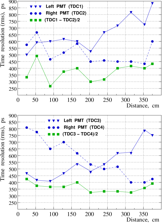
Two trigger counters selected the cosmic MIPs going through the sandwich modules placed one above another. The upper trigger counter was 15 mm wide and 80 mm long to localize the hit position. The 4 PMT signals from the modules are sent to analogue fan-outs where they are distributed to charge-sensitive ADCs and leading edge discriminators. Before measurements of the module response, single photoelectron peak of each phototube was calibrated and these values are used to calculate the light yields. Previous experience with FEU-115M PMTs shows that the single photoelectron peak can drift by 5%. The accuracy of the light yield measurements is determined mainly by this systematic error. The light yield (l.y.) was scanned along the modules with a step of 30 cm. Results are shown in Fig. 2.
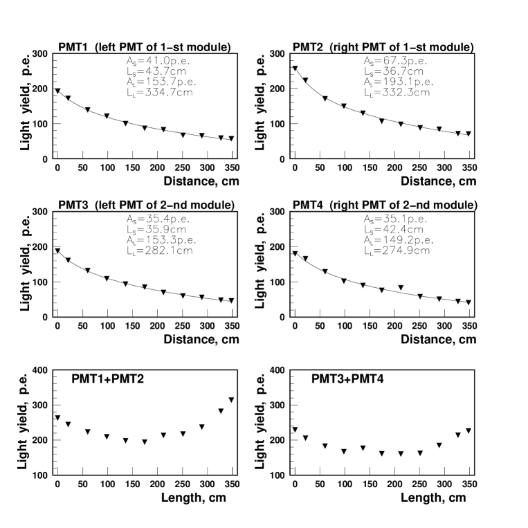
The first module yielded about 195 p.e./MIP at the center, corresponding to 9 p.e./MeV, and over 300 p.e./MIP near the ends. The second module yielded 160 p.e./MIP at the center. The smaller l.y. is explained by the different quality of available WLS fibers that resulted in a lower attenuation length for the second module. The l.y. attenuation curves were fitted with a sum of two exponents. At distances greater than 1 m the attenuation length of fast Bicron fibers was found to be 333 cm in the first module, and 280 cm in the second module.
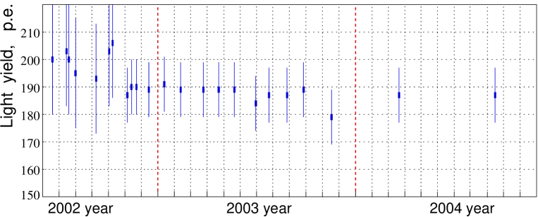
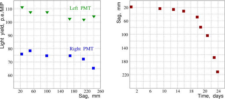
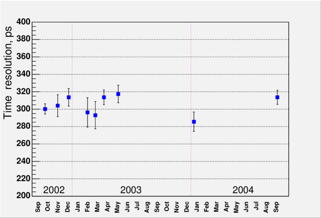
The light output stability of the first module is shown in Fig. 3. The reference point is the module center. During the first 5 months of testing the trigger counters were moved along the module. After that the test bench was fixed to periodically readout the data. As it can be seen in Fig. 3 the l.y. is stable over 2 years within the 5% systematic error. The second module was subjected to the sagging test. During test the both ends rested upon the supports, and the sag was measured as deviation of the module center from the straight horizontal level. Results are shown in Fig. 4. The initial deviation was 2 cm. After 2 weeks the flexure under its own weight led to fast uncontrolled bowing. However the sag effect on the light yield is rather weak.
IV Timing
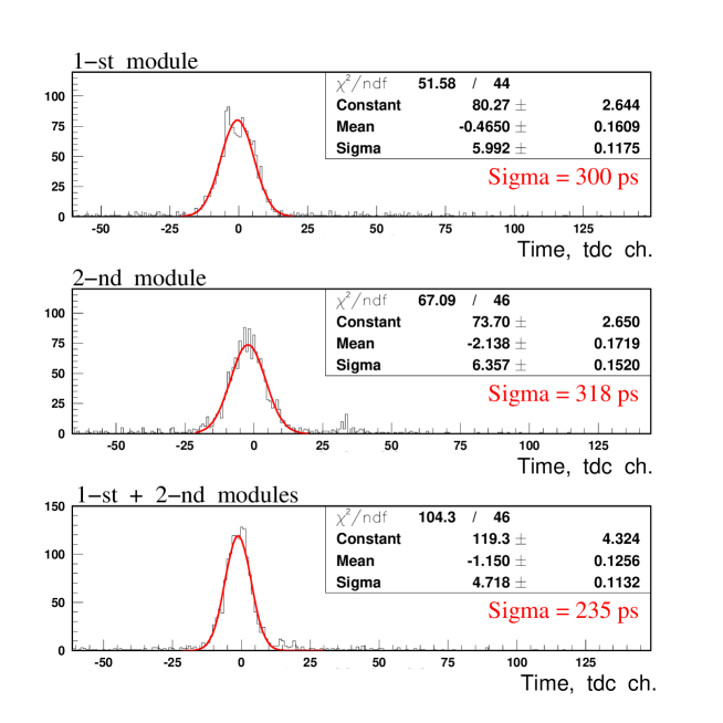
A time-amplitude correction was applied to all signals from the sandwich modules. To suppress the timing spread caused by the trigger counters we used the combination . The timing spectra obtained in this way at the module centers are shown in Fig. 5. The time resolution is 300 ps for the first module, and slightly worse for the second module. Cosmic MIPs deposit 21 MeV in the scintillator of a single module. The combination produces a resolution of 235 ps. The resolution dependence on the light output is demonstrated in Fig. 6.
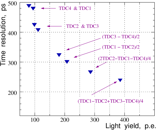
Only central values are shown as the error is determined by unspecified systematic factors. Fitting the points with the root square law yields , where E is the light yield in photoelectrons. Taking into account that the visible fraction for a module is 0.4 the time resolution for photons can be brought to
V C-bent sandwich module
Full photon veto coverage was the motivation to design the C-bent sandwich modules which can be used to build side walls in the photon veto barrel. The barrel roof and floor are made of straight sandwich modules. Phototube readout for the barrel side walls would create a dead space degrading the photon detection efficiency. C-bent modules were proposed to resolve the problem as shown in Fig. 9.
There will be no longer be any projective gaps for photons emerging from the flat kaon beam. The C-modules are installed vertically, since for the horizontal alternative the bent part of the modules produces directions with low radiation thickness.
To check the method a few scintillator slabs of 1 m length with WLS readout were produced. Their light output was measured and then the slabs were bent using the different thermal treatment. The light output was measured again with the same phototube. The best result shows no light yield drop, the average loss in l.y. for other bent slabs was about 5%.
The prototype module was bent by the following procedure:
-
1.
First, 7 mm thick slabs were produced with length from 3.3 to 4 m applying the standard methods. Two-mm deep grooves run along the slab with spacing of 7 mm. Y11 Kuraray WLS fibers of 1 mm diameter were glued into the straight grooved slabs of extruded polystyrene scintillator covered by chemical reflector.
-
2.
The bent slabs were prepared by locally heating the bending place with a warm iron cylinder. The cylinder temperature was stabilized using water flow through the cylinder. The thermostat controls this temperature.
-
3.
Bending over the cylinder with 10 cm radius is done such that the fibers run along the inner curvature of the slab. Optimum conditions were selected to heat up and cool down the scintillator with fibers avoiding its shape deformation. The bent slabs are shown in Fig. 10.
-
4.
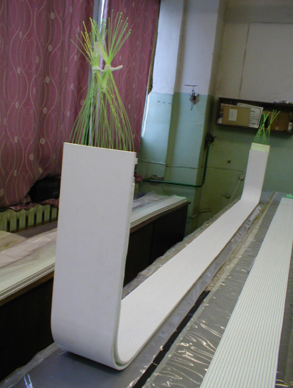
The prototype module had been assembled in a frame jig from 15 bent scintillator slabs and 15 layers of 1 mm thick lead by gluing them together. The module in a jig is shown in Fig. 11. 300 WLS fibers are squeezed then at both ends into the collet connectors.
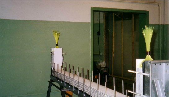
The prototype module was tested with cosmic rays in the central part. The light yield of the C-module is 500 p.e./MIP from both ends or about 24 p.e./MeV. It is a factor of 2.5 larger than the light output for the straight sandwich modules due to multi-clad Y11 fibers. The light output from a single end along the straight part of the C-module is shown in Fig. 12.

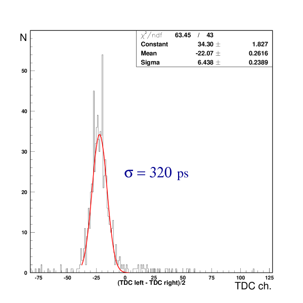
The long attenuation length is measured to be 4.3 m. This value is close to Kuraray data that demonstrates the quality of fibers after thermal bending. Although Y11 fibers have a longer decay time than Bicron ones, the obtained time resolution of =320 ps (see Fig. 13) is close to the result (300 ps) for the straight modules. After 8 months the measured light yield at the center show no change.
VI Conclusion
Long prototype photon veto detectors for the BNL experiment KOPIO were manufactured and tested with cosmic rays. The sandwich modules consist of 15 layers of 7 mm thick extruded scintillator and 15 layers of 1 mm lead absorber. One of the modules was bent to have a C-shape. Readout is implemented with WLS fibers. The average yield was measured with cosmic rays to be about 9 p.e./MeV in the center for straight modules with fast single-clad Bicron fibers. The light yield for the C–bent module is 2.5 times larger due to multi-clad Y11 Kuraray fibers. The time resolution for all modules is about 300 ps. The light output of one of the straight modules was monitored over 2 years and shows no degradation beyond the measurement errors. The light output of the thermally bent C-module is also stable after 8 months.
VII Acknowledgment
We gratefully acknowledge NSF support through the KOPIO Experiment.
References
- (1) I.-H. Chiang et al., BNL Proposal E926, Measurement of , September 1996.
- (2) M. Atiya et al., Nucl. Instr. and Meth. A321 (1992) 129.
- (3) K. Abe et al., KEK-Preprint-2000-89, August 2000.
- (4) Yu. Kudenko et al., Nucl. Instr. and Meth. A469 (2001) 340.
- (5) O. Mineev et al., Nucl. Instr. and Meth. A494 (2002) 362.