On the physical origins of the negative index of refraction
Abstract
The physical origins of negative refractive index are derived from a dilute microscopic model, producing a result that is generalized to the dense condensed phase limit. In particular, scattering from a thin sheet of electric and magnetic dipoles driven above resonance is used to form a fundamental description for negative refraction. Of practical significance, loss and dispersion are implicit in the microscopic model. While naturally occurring negative index materials are unavailable, ferromagnetic and ferroelectric materials provide device design opportunities.
pacs:
42.25.Bs, 42.70.-a, 42.25.Fx, 41.20.Jb, 78.20.Jq, 78.20.Ls, 71.36.+c, 42.70.Mp, 76.50.+gIn 1968, Veselago suggested that a material with a negative index of refraction would enjoy certain peculiar properties. Foremost among these was negative refraction, where a ray incident on the interface of such a material would refract on the same side of the normal rather than away from it Veselago (1968). The subject lay dormant until 1999, when Pendry proposed designs for magnetic metamaterials Pendry et al. (1999) that were subsequently implemented by Shelby et al., along with a dispersed electric metamaterial, to demonstrate negative refraction in 2001 Shelby et al. (2001). Despite the fact that no naturally occurring negative index material is available, there has been a surge in interest, particularly with regard to the prospect of creating a perfect lens Pendry (2000).
In this Letter, we explore the physical origins of the negative index of refraction. The formalism developed here differs from previous macroscopic descriptions of negative refraction in that it is developed from a microscopic model consisting of an array of electric dipoles and magnetic dipoles undergoing precession due to an external static magnetic field. By considering the extension of the microscopic model to a macroscopic electromagnetic description, a physical basis for why the propagation speed of light, , should appear negative when the permittivity and permeability are simultaneously negative is established. This extends the macroscopic arguments originally formulated by Veselago Veselago (1968), and, for example, applied under the context of a Drude model Ziolkowski and Heyman (2001), to include a physical, microscopic basis. Finally, we use the microscopic model to suggest some possibilities for the use of ferromagnetic and ferroelectric materials to enhance the capabilities of negative index metamaterials.
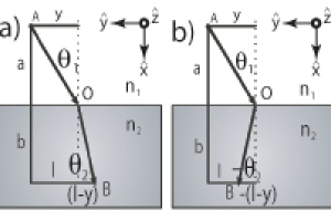
To illustrate how negative refraction might arise, we apply Fermat’s principle of least time M.Born and Wolf (1980) to the case of negative refractive index materials and interpret it in terms of least action. Consider the path of least action for a stream of photons in vacuum () incident on a homogeneous, isotropic material with an index of refraction . The most probable path is determined by the path of stationary phase, which corresponds to an extremum in the spatial derivative of the total travel time through all possible paths. This is well established for the case of positive refraction. From the diagram in Figure 1(a), the optical path length in vacuum from source A to the interface point O is , and in the semi-infinite material from O to B it is . To find the extremum in the time of travel from A to B, we form , with and fixed at arbitrary values, which upon substituting for the optical path lengths gives , with . Recognizing the trigonometric relations and , this can be rewritten in the familiar form of Snell’s law: . If we postulate that the photons refract to the other side of the normal, as depicted in Figure 1(b), then , which implies that the angle of refraction becomes . The extremum for this optical path gives , which can only be satisfied if . Since and , Snell’s law is found to be valid for both positive and negative refraction, provided we allow for the possibility of a negative index of refraction. The curvature becomes . For , the curvature is positive, indicating that Fermat’s result indeed gives the minimum time (and distance). Interestingly, for , the curvature is negative, indicating a maxima. In terms of least time this result does not make much sense, since the path for negative refraction corresponds a maximum, but in terms of least action, the path is acceptable upon recognizing that negative index materials are causal in an energy sense but not in a temporal sense, an issue we address further in relation to a microscopic model.
The disparity between the frequency dependent speed of light in a material and the constant speed of photons in a vacuum is resolved by recognizing that photons impinging on a medium can drive resonances in that medium, which may radiate and contribute to the total scattered field. When there is a difference in phase between the source and radiated field, the wavefronts at the detector will appear to be advanced or retarded with respect to the source, and it is on this basis that the concept of negative velocity is explained.
To relate our microscopic model to the index of refraction, which is a macroscopic phenomenon, we employ an approach developed by Feynman, thereby extending the physical origins of the index of refraction to include negative index materials Feynman et al. (1965). Our system consists of a monochromatic plane wave source of radial frequency traveling at the speed of light in vacuum, , in the -direction, incident on a slab of material of thickness , and a detector on the other side of the slab, sufficiently far away. If the slab were removed, then the observed travel time to the detector, a distance from the source, would be commensurate with the speed of light in vacuum. When the material is present and an observed delay or advance in arrival time is assumed, such that the observed speed is , consider that the electric field at the detector is
| (1) |
which is the source field of initial strength (neglecting amplitude scatter in the dilute limit) multiplied by a phase term. Feynman showed that for dilute media in which the phase term is small, (1) can be written in a more suggestive manner as Feynman et al. (1965)
| (2) |
Written this way, it is clear in (2) that the plane wave at the detector is the sum of the source term (the incident field without the material) and a material response term (the scattered field). This representation is thus consistent with the Born approximation for scattered photons.
To provide a mechanism for the apparent augmentation of the arrival time of the photons, we employ a microscopic model that replaces the slab with a thin sheet of electric and magnetic dipoles, find the fields due to each source, and then apply superposition. We assume a Lorentz electric dipole resonance and a Bloch magnetic resonance.
The field radiated in the direction by a thin sheet of microscopic electric dipoles is
| (3) |
with the relative electric susceptibility given by Born and Huang (1954)
| (4) |
where is the static susceptibility, is the oscillator density, the dipole charge, the permittivity of free space, the reduced mass of the charges in the normal mode that results in radiation, the electric resonance frequency, and is a phenomenological damping constant.
Also within our slab is a sheet of magnetic dipoles with a static external field applied in the -direction. Equivalently, we could assume a slab of ordered spins, where the static magnetic field is provided by dipolar coupling, as in the case of a ferromagnetic material. The equation for the field radiated by a magnetic dipole sheet, , can be shown to be of the same form as (3) with the replacement of with , the relative magnetic susceptibility for a Bloch resonance, which is given by Slichter (1980)
| (5) |
where is the ratio of the magnetization and the static magnetic field that induced it, is the magnetic resonance frequency, and is the spin dephasing time.
The field due to both the radiating electric and magnetic dipoles, using (3) and its magnetic analog, is then
| (6) |
Comparing the microscopic equation of (6) with our previous macroscopic expression in (2), the index of refraction can be expressed in terms of the microscopic susceptibilities as
| (7) |
We will employ some foresight and recognize that (7) is the same as the index of refraction derived from the macroscopic Maxwell’s equations for dense media of arbitrary thickness in the limit of small susceptibilities. Accordingly, we assume the usual form for the index of refraction, , where the relative permittivity is and the relative permeability is , so as to not limit our discussion to dilute materials with weak susceptibilities. What we gain by doing so is that a layer of dipoles can augment the source field for subsequent layers of dipoles.
To describe the effect of the microscopic susceptibility on wave propagation, we introduce the permittivity, , and permeability, , in polar form into the index of refraction (), and wave admittance (). is the free space admittance, the inverse of the wave impedance. The domain for the index of refraction and the wave impedance come from the range of the permittivity and the permeability. Accordingly, with the loss implied by the damping in (4) and (5), the permittivity and permeability are restricted to the upper-half of the complex plane, in order for a propagating wave to lose energy (under the assumed convention). Thus, is in the interval , and the index of refraction shares the same interval, since . However, the domain of the wave impedance phase is , since . Note that loss becomes more significant in the neighborhood of the resonances. However, even perturbational loss poses limitations on the potential amplification of evanescent fields in a negative index slab Webb et al. (2004).
The effect of the index of refraction on the source field as it propagates through the slab is seen by introducing the polar form of the index of refraction into (1) and replacing the thickness with the independent coordinate system in Figure 1. From (1), ignoring the time dependence, and assuming , we get . By use of either the right hand rule or Faraday’s law, we find that the magnetic field associated with propagation in the -direction is . Thus, the wave admittance introduces a relative phase shift in the electric and magnetic field, which has consequences on power flow.
In the case of a material with only electric dipole coupling, the value of is restricted to the interval and . This limits the range of and to the interval . However, if we allow for the simultaneous existence of magnetic and electric dipole coupling, we find that the interval for the phase of the index of refraction becomes and the interval for the wave admittance becomes . The most interesting result of this additional phase contribution comes from consideration of a material that without the magnetic dipole resonance would exhibit a bandgap for the frequency under consideration, assuming negligible loss, resulting in an evanescent wave. If we introduce a small magnetic phase contribution, then we find a return to a propagating wave solution. In the lossless electric dipole only case, the field does not propagate and does not carry real power because the electric and magnetic fields are radians out of phase. However, when both electric and magnetic dipole coupling is present, the phase contribution from the magnetic dipole can ’undo’ the deleterious effects of the electric dipole by partially restoring the relative phase of the electric and magnetic fields such that power can flow. In the remarkable case that and are both equal to (or 0), it follows that (or 0) and , and we find that propagation results with no attenuation, giving a time average Poynting vector . If the magnitudes of the relative permittivity and permeability are chosen to be identical, then unimpeded propagation takes place, i.e., there is no back-scattered wave.
The negative refractive index range, in , corresponds to the frequency range where , with . These overlapping frequency bands for the resonances in (4) and (5) define the frequencies where propagation can occur. Within this band, a negative phase velocity occurs, i.e., , where . This means that with advancing time, the wave crests move in the -direction. However, in this same frequency range, the group velocity (), which describes the power flow of a wave packet, is positive. This can be established from with use of (7), (4), and (5). As a consequence, in the frequency range of negative refractive index. Therefore, conservation of power holds, i.e., with incident power in the -direction, there is power flow in the -direction in the negative refractive index medium. Furthermore, causality can be established based on power flow, equivalent to the procedure used in developing the Kramers-Kronig relations for permittivity Jackson (1999). Note that conservation of energy is thus the basic metric for causality, and others such as least time based on phase (velocity), for example, Fermat’s least time argument, require a revised interpretation from the standard view for positive index materials.
The formalism developed here has direct application to ferroelectric and ferromagnetic resonances as either the electric dipole or the magnetic dipole source in a negative index material. A good metric for the resonance frequency of ferromagnetics is the Bohr magneton divided by Planck’s constant, which can conveniently be written as GHz/Tesla Slichter (1980). This places the possible range of resonance frequencies somewhere between and GHz. Ferroelectrics do not have such a convenient metric, but the resonant frequencies tend to be in ’s of THz Born and Huang (1954). Antiferromagnets can sometimes have resonance frequencies near a THz, but they have relative susceptibilities similar to paramagnetic materials, which are only slightly greater than unity. It may, however, still be possible to observe a negative index with an antiferromagnetic-ferroelectric composite. Within their respective frequency range, ferroelectrics and ferromagnets offer very strong resonances, with susceptibilities approaching up to in both. The frequency range over which the material may have a negative index is given by the extent of the bandgap in the limiting material, i.e., the one with the smallest bandgap, where the bandgap is the region between the resonance frequency () and it’s conjugate frequency () . In ferroelectrics, the latter is given by the Lyddane-Sachs-Teller relation, , where is the resonance frequency usually associated with a transverse optical phonon in a ferroelectric crystal, is the static dielectric constant and is the high frequency permittivity usually associated with electronic resonances Born and Huang (1954). In ferromagnetics, the bandgap is equal to , where is the relative permeability above resonance Kittel (1987). These materials offer an alternative to providing both electric and magnetic resonances with a metamaterial. Furthermore, ferromagnetic materials can be employed now with existing metamaterials that operate normally around GHz. One advantage in doing so is to exploit the modest tunability of the ferromagnetic resonance and the associated bandgap to provide a tunable negative index that could possibly be used in a device, e.g., a switch that refracts light one way or the other, based on the static magnetic field applied. Ferroelectrics also offer benefits for application to existing THz frequency split ring resonators Yen et al. (2004), in that the electric field of an electromagnetic wave can be imaged directly as it propagates through the ferroelectric material Koehl et al. (1999).
To summarize, by determining the path of stationary phase for a stream of photons incident on an arbitrary dispersive medium, we found that negative refraction occurs when the index of refraction is negative, indicating that the photons traverse this path with what seems to be a negative phase velocity. While Fermat’s least time principle correctly predicts Snell’s law for refraction at an interface with a negative refractive index material, it does not produce a least time solution, a consequence of the negative phase velocity. The microscopic model we have used for electric and magnetic dipole interactions provides a basis for the collective oscillator phase shift that results in negative phase velocity in the case of negative refractive index. We found that when the electric and magnetic dipoles in this model have nearly the same resonant frequency, the augmentation of the electric component by the Lorentz dipoles is partially compensated for by the Bloch dipoles acting on the magnetic component, where the phase shifts in the electric and magnetic components of the field are directly related to the phase of the microscopic electric and magnetic dipoles. While any simultaneous resonance in the electric and magnetic constitutive parameters can provide a model for negative refraction, the dilute microscopic interaction model presented, and its generalization to the dense limit, provide a foundation for macroscopic interpretations. As a consequence, it is clear that dispersion and loss cannot be circumvented. Also, the dipole resonance models presented have a finite bandgap that is representative of physical systems such as ferroelectrics which can, with a concomitant magnetic resonance bandgap, provide negative refractive index over a finite frequency range. While there are ferroelectric and ferromagnetic materials that may be candidates for negative refractive index applications, achieving simultaneous bandgaps in an appropriate frequency range and having other satisfactory properties, such as low loss in the composite system, appears challenging. On the other hand, use of one or the other physical resonance, i.e., ferroelectric or ferromagnetic materials, in combination with a metamaterial implementation for the other resonance, is tractable and may yield practical functionalities.
References
- Veselago (1968) V. G. Veselago, Sov. Phys. Uspekhi 10, 509 (1968).
- Pendry et al. (1999) J. B. Pendry, A. J. Holden, D. J. Robbins, and W. J. Stewart, IEEE Trans. Microwave Theory Tech. 47, 2075 (1999).
- Shelby et al. (2001) R. A. Shelby, D. R. Smith, and S. Schultz, Science 292, 77 (2001).
- Pendry (2000) J. B. Pendry, Phys. Rev. Lett. 85, 3966 (2000).
- Ziolkowski and Heyman (2001) R. W. Ziolkowski and E. Heyman, Phys. Rev. E 64, 056625 (2001).
- M.Born and Wolf (1980) M.Born and E. Wolf, Principles of Optics (Pergamon, New York, 1980), 6th ed.
- Feynman et al. (1965) R. P. Feynman, R. B. Leighton, and M. Sands, The Feynman Lectures on Physics, Volume I (Addison-Wesley, New York, 1965).
- Born and Huang (1954) M. Born and K. Huang, Dynamical Theory of Crystal Lattices (Oxford, Oxford, 1954).
- Slichter (1980) C. P. Slichter, Principles of Magnetic Resonance (Springer-Verlag, New York, 1980).
- Webb et al. (2004) K. J. Webb, M. Yang, D. W. Ward, and K. A. Nelson, Phys. Rev. E (2004).
- Jackson (1999) J. D. Jackson, Classical Electrodynamics (Wiley, New York, 1999), 3rd ed.
- Kittel (1987) C. Kittel, Quantum Theory of Solids (John Wiley and Sons, New York, 1987), 2nd ed.
- Yen et al. (2004) T. J. Yen, W. J. Padilla, N. Fang, D. C. Vier, D. R. Smith, J. B. Pendry, D. N. Basov, and X. Zhang, Science 303, 1494 (2004).
- Koehl et al. (1999) R. M. Koehl, S. Adachi, and K. A. Nelson, J. Chem. Phys. 110, 1317 (1999).