The D Silicon Track Trigger
Abstract
The Level-2 Silicon Track Trigger preprocessor (L2 STT) of the D detector in Run II is described. It performs a precise reconstruction of charged particle tracks in the Central Fiber Tracker (CFT) and the Silicon Microstrip Tracker (SMT). Events with displaced tracks originating from the decay of long living particles such as hadrons are triggered on. The presence of quarks contained in such hadrons is relevant for physics and crucial as signature of top quark and Higgs boson decays.
1 Introduction
In Run II the Fermilab Tevatron collider operates at a center-of-mass energy of . To keep the rejection of background events while maintaining high efficiency for physics processes of interest, the D trigger had to be upgraded and accommodated to the decreased beam crossing time of which requires minimized dead-time between collisions. The D Silicon Track Trigger (STT) [1] is the newest addition to this upgrade.
2 D tracking and trigger
The D trigger consists of three levels. The first level is hardware based and compares data with preprogrammed patterns. The STT belongs to the second level trigger and constitutes a preprocessor for the Silicon Microstrip Tracker (SMT). The output of Level 2 preprocessors is sent to the third trigger level which applies sophisticated reconstruction algorithms to the data. To maintain a dead-time below five percent the mean decision time for the Level 2 trigger has to be kept below subdivided in two halfs for the preprocessors and the global L2 decision.
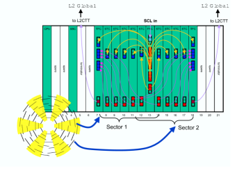
The STT is fed with information from silicon strip detectors arranged in four concentric layers in six cylindrical barrels around the beam axis (fig. 1, left). All detectors have axial pitch strips (parallel to the beam line). The STT subdivides the inputs from the barrel detectors into six independent azimuthal sectors. In addition to the SMT information the STT receives up to 46 tracks per sector each event from the Level 1 Central Track Trigger (CTT) which makes trigger decisions on tracks from the Central Fiber Tracker (CFT).
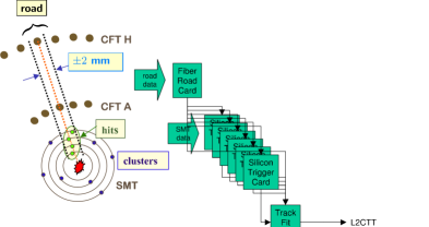
The STT builds clusters from the SMT raw hits and defines wide roads around the Level 1 CTT tracks (fig. 1, right). The CFT hits of the inner- and outermost layers are used together with SMT clusters of at least three out of four layers for the STT track fitting. The determined track fit parameters are sent to the Level 2 CTT/STT trigger and to Level 3.
3 STT hardware design
The STT consists of six identical crates, each covering two neighbored azimuthal SMT sectors (fig. 1, left). A crate caries an input output controller (IOC) to operate the crate, a single board computer (SBC) for Level 3 data submission and twelve custom-designed VME boards with programmable processors and daughter boards.
The STT motherboard is a 9U400 mm VME64x-compatible card containing three 33 MHz PCI busses to communicate between the logic daughter board (either a Fiber Road Card (FRC), a Silicon Trigger Card (STC) or a Track Fit Card (TFC)), serial link boards and the data buffer controller (BC) board.
The FRC consists of four functional elements which are a trigger receiver which communicates with the trigger framework bidirectional, a road receiver which receives tracks from the L1 CTT trigger, a trigger/road data formatter which combines the road and trigger framework information and a buffer manager which controls the buffering and readout to Level 3.
The STC receives raw hits from the SMT barrel detectors. Bad strips are masked and pedestal/gain corrections are applied via Look-Up-Tables (LUT). Adjacent SMT hits are clustered. Clusters of axial strip detectors are matched to roads around CFT tracks via LUT’s and sent to the Track Fit Card (TFC).
The TFC performs the final cluster filtering (closest cluster to road center) and two dimensional linearized track fitting of the form
| (1) |
where is the radial distance from the beam spot position to the cluster, its azimuth, the impact parameter, the track curvature and its direction at the point of closest approach. The fit is performed with help of precomputed matrix elements stored in LUT’s exploiting two CFT hits in addition to the SMT clusters.
4 Performance
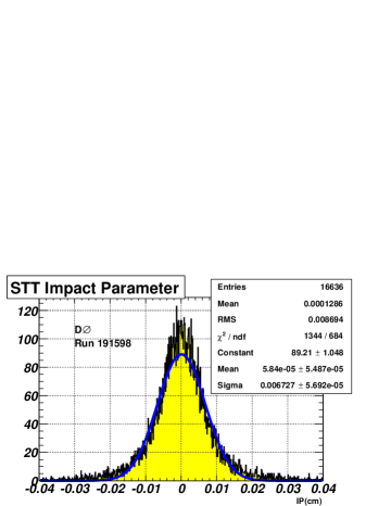
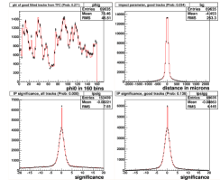
The impact parameter of the STT integrated over all track transverse momenta has been measured to be (fig. 2, left, preliminary) including the beam spot size of about and the spatial resolution of the axial SMT ladder detectors, obtained offline.
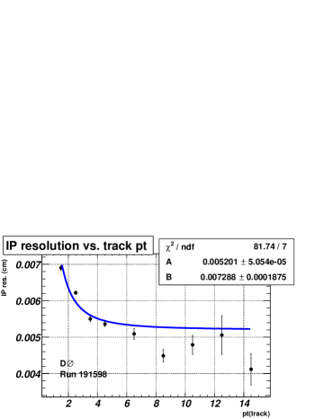
The measured impact parameter resolution of the STT as a function of track transverse momentum (fig. 2, center, preliminary) increases towards lower track transverse momenta due to multiple Coulomb scattering. The fit function
| (2) |
has been used.
Fig. 2 (right) shows a monitoring plot with the impact parameter significance distribution of the STT. The red curve is a reference histogram, the black dots are data. In the present test trigger a cut on events with at least one track with impact parameter significance above has been implemented.
5 Conclusions
The STT measures impact parameters of tracks and their significance which allows to select large samples of events containing long living particles such as hadrons in the presence of enormous background through triggering on displaced tracks. Presently the STT operates as a test trigger during data taking and will be fully commissioned with the next revision (V14) of the D trigger list.
6 Acknowledgments
Many thanks to the staff members at Fermilab, collaborating institutions and the Altera and Xilinx Corporations for contributions. Major project funding has been granted from the Department Of Energy (DOE) and the National Science Foundation (NSF) under the Major Research Instrumentation (MRI) Program Award No. 9977659,9/1/1999.
References
- [1] D Collaboration, A Silicon Track Trigger for the D Experiment in Run II, http://www-d0.fnal.gov/trigger/stt/sttdesign/uli/tdr_980318.ps, D Note 3516, Fermilab 1998.