Surface plasmon polariton propagation around bends at a metal-dielectric interface
Abstract
We analyze theoretically the propagation of surface plasmon polaritons about a metallic corner with a finite bend radius, using a one-dimensional model analogous to the scattering from a finite-depth potential well. We obtain expressions for the energy reflection and transmission coefficients in the short wavelength limit, as well as an upper bound for the transmittance. In certain cases we find that propagation on non-planar interfaces may result in lower losses than on flat surfaces, contrary to expectation. In addition, we also find that the maximum transmittance depends non-monotonously on the bend radius, allowing increased transmission with decreasing radius.
Structured materials which allow nanoscale control of light are necessary for achieving compact integrated photonic devices. While the size of standard optical components and beams is typically set by the diffraction limit, low dimensional excitations such as surface-plasmon polaritons may be confined to dimensions much smaller than the wavelength of light. Surface-plasmon polaritons (SPPs), coupled modes of plasmons and photons, are excited when visible electromagnetic (EM) radiation couples into surface guided modes at metal-dielectric interfaces [1, 2]. When propagating along flat interfaces, these are essentially two-dimensional (2D) waves, with an EM field intensity which peaks at the interface and decays exponentially into the two adjoining media.
Recently, SPP waveguiding and bending in nano-patterned metallic films were studied [3]. Alternately, it was shown that EM energy may be efficiently transported by near field coupling in plasmon waveguides comprised of ordered arrays of metal nanoparticles [4]. Optical elements such as linear waveguides [5], mirrors, beamsplitters and interferometers [6] were recently demonstrated.
Interestingly, while significant progress has been made in understanding SPP propagation in nano-structures, certain fundamental issues pertaining to their guiding on smooth metallic films remain unknown. In particular, quantifying guiding and energy losses in SPPs propagating around bends in metal-dielectric interfaces is of great importance, as it should set a limit on feature size in certain plasmonic-circuit devices. Previously, the problems of refraction [7] and reflection of SPPs [8] at interfaces have been addressed in this context. In this Letter we present a study of the efficiency of SPP propagation at a curved metal-dielectric interface in the short wavelength limit.
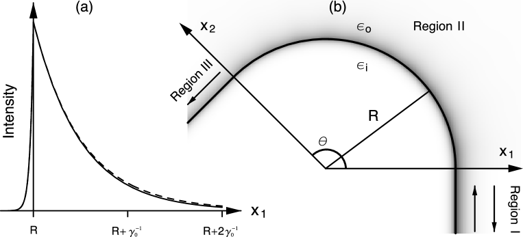
The geometry we study is that of propagation about a rounded edge, as shown in Fig. 1. SPPs are incident along the interface from Region I, and propagate counterclockwise through the bend in Region II, in the direction of Region III. We calculate the energy-reflection and transmission coefficients, as well as bend-induced radiation losses. For lossy metals absorption losses are also evaluated.
Our approach exploits known expressions for the SPP fields in each region and matches them at the two ends of the bend. The procedure differs from related numerical techniques [9] in that we consider the SPP itself as the incident wave, with the goal of manipulating it as a well-defined quasi-particle in a non-trivial geometry. Favorable conditions for this will be seen to emerge in the short-wavelength limit, and we use this to arrive at analytic expressions.
The solutions for SPP propagation on an infinite flat surface and on cylindrical surfaces are known analytically [2]. On a flat interface, SPPs at frequency are two dimensional waves, decaying exponentially into the two adjoining media, with decay constants in the metal and in the dielectric. In the limit the interference of SPPs in Regions I and III is negligible, allowing us to use the infinite flat surface 2D solution in these regions.
We construct the solution in Region II using the known solutions for SPPs propagating around the perimeter of an infinitely long cylindrical metal rod of radius [2]. Here, the magnetic field is given by
where and is the Bessel function. The set is determined by the metal boundary matching equation,
| (1) |
where , is the Hankel function of the first kind, and the prime denotes differentiation with respect to the argument. Assuming real, one finds to be complex, as a consequence of radiation loss and absorption in the bend. Since the wave depends on as , where is measured from the axis, only solutions with are physical for damped propagation.
Solving exactly for the transmission and reflection coefficients requires matching an infinite number of solutions at the boundaries along the - and -axes separately. However, it is possible to render this problem tractable by a few simple approximations. Noting that the incident SPP carries momentum proportional to , in the short wavelength limit its angular momentum with respect to the origin is approximately equal to . In Region II the solution has angular momentum proportional to the various -values. Conservation of angular momentum dictates that the incident SPP couple predominantly to that cylindrical mode with closest in value to . Therefore it is necessary to consider only a single term of the expansion. Formally, this is shown by examining the set and noting that it contains an element which minimizes the mismatch between the field profiles perpendicular to the surface. The role of angular momentum conservation in this matching problem is analogous to that of tangential momentum conservation in refraction at a dielectric interface. We call the clockwise and counterclockwise modes corresponding to the fundamental modes. In the short wavelength limit of a fundamental mode , and the decay rate is Thus, near the interface, identical to the fields in the metal in Regions I and III. Similarly, in the dielectric [10].
The modes have decay rates not as close to as that of the fundamental mode’s. For this reason, it is possible to assume that in the short wavelength limit the incident SPPs couple predominantly to the fundamental modes and ignore other mode coupling. In order to satisfy the standard Maxwell boundary conditions it is therefore necessary to match only a small number of solutions at a single point on each axis, at a distance from the origin. The boundary conditions are thus also satisfied approximately over the entire extent of the axes. As can be seen from Fig. 1, the mode mismatch at the boundaries may be very slight. The problem has now essentially become one dimensional (1D), analogous to scattering from a 1D finite potential well [11]. Since the allowed -values are always complex, bound-state solutions in the well do not exist. This distinguishes the SPP on a bent surface from waveguide bends enclosed on all sides by infinite potential walls [12].
Applying the appropriate boundary conditions to the fields at the two boundaries results in the familiar expression for the transmittance
| (2) |
When the losses in the metal are accounted for, increases with , such that when the transmittance becomes
| (3) |
The reflectance R may be obtained in a similar manner. In the limit these expressions become exact.
For lossless metals, the bend-induced radiation losses are simply given by . Accounting for absorption in the metal we find that A now includes both radiation and absorption losses. We extract the radiation losses by integrating the Poynting vector for unit incident flux in Region II at :
| (4) |
Since the radiation carries angular momentum with respect to the origin, the energy radiated into the far-field from the surface at propagates at an angle with respect to the axis, setting the lower integration limit in (4). In the short-wavelength limit only the amplitude of the forward-propagating mode is significant, therefore the radiation losses are well approximated by integrating only this mode. To obtain we use a stationary phase approximation. The position-dependent phase is , and the vector normal to a surface of constant phase is . The change in angle as the wave propagates a radial distance is , giving .
We have carried out calculations for typical values of silver () in air () when and . Ignoring the losses in the metal we find , and . When the losses are included the results change drastically to , and , indicating that most of the energy is lost to absorption in the metal. Comparing the latter overall absorption and radiation losses to the energy absorbed when SPPs propagate the equivalent arc distance on a flat surface, we find that propagation on a non-planar interface may result in losses. We explain this counterintuitive result using an analogous picture of semi-classical motion under an effective potential in a central potential field. In the short wavelength and large angular momentum limit the SPP fields propagating on the curved interface sample less of the metal volume than that available when propagating on a flat interface, hence the reduced absorption.
We evaluate the accuracy of our result by examining the coupling efficiency of a single mode on a flat interface to a fundamental mode . We define this by
| (5) |
where . We find that the condition constitutes a stricter criterion for the validity of our approximation. When the latter holds, the incident SPP couples predominantly to the fundamental modes, making the approach described above self-consistent. For example, when , , and , for , rendering our result applicable. On the other hand, for we obtain , signifying that the expression is not reliable because the coupling to modes other than the fundamental can no longer be neglected. In this regime a more physical quantity is the upper bound for the transmittance, given from (3) by
| (6) |
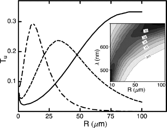
Here we neglect reflections at the boundaries between the different regions, thus excluding interference with the counter-propagating mode in Region II. To understand why this is an upper bound, recall that in the wavelength range of interest, where the metal is not very lossy, . Since the wave depends on as , modes with large decay rapidly. Thus, the transmission in the presence of coupling to non-fundamental modes does not exceed , and the latter is a true upper bound. Fig. 2 is a plot of . A peak is clearly visible, moving to higher values of as the wavelength increases. To the right of the peak, at large radii of curvature absorption losses in the metal dominate, and the maximum transmittance decreases with increasing radius. To the left of the peak radiation due to the high curvature is the dominant loss mechanism, leading to a rapid drop in . At very high curvature (m) there is a change in trend, and starts to increase with decreasing (see Inset.) When calculating the radiation loss per arclength, we find that for this range of radii it increases slower than elsewhere, allowing to increase even as attains very small values. This anomalous behavior can be observed for all wavelengths, and is independent of the dispersion in the metal.
The formalism developed here may also be used to analyze the complementary reversed geometry, where the metal occupies three quadrants in space, and the SPPs propagate around a dielectric void in it. Surprisingly, in this case we find that in the single mode approximation SPP propagation around the bend is non-radiative. Separate work will address radiation and absorption processes in this system in greater detail.
In summary, we have analyzed the scattering of SPPs at a curved metal-dielectric interface in the short wavelength limit. Utilizing an analogy to a quantum mechanical 1D finite square well we obtained the energy transmission and reflection coefficients. Interestingly, propagation on a curved interface may result in lower losses than at a flat metallic surface, due to the unique field distributions which arise in our system. An expression for an upper bound on the transmittance was also obtained, showing that at high curvature radiation is the main loss mechanism, while at low curvature material losses dominate. An unexpected behavior where the maximum transmittance increases with curvature was also observed. We explain this as an interplay between various loss rates in the system. These results shed new light on the mesoscopic behavior of SPPs, and should play an important role in the design and optimization of SPP devices. Future work will address SPP propagation in waveguides, splitters and interferometers.
J.U.N. acknowledges support from NSF Grant ECS-02-39332; K.H. and M.D. acknowledge support from NSF Grant DMR-02-39273 and ARO Grant DAAD19-02-1-0286.
References
- [1] V. M. Agranovich, D. L. Mills, eds., Surface Polaritons (North Holland, Amsterdam, 1982).
- [2] B. E. Sernelius, Surface Modes in Physics (Wiley, Berlin, 2001).
- [3] S. I. Bozhevolnyi, J. Erland, K. Leosson, P. M. W. Skovgaard, J. M. Hvam, Phys. Rev. Lett. 86, 3008 (2001), S. I. Bozhevolnyi, V. S. Volkov, K. Leosson, A. Boltasseva, Appl. Phys. Lett. 79, 1076 (2001).
- [4] M. Quinten, A. Leitner, J. R. Krenn, F. R. Aussenegg, Opt. Lett. 23, 1331 (1998).
- [5] S. A. Maier, P. G. Kik, H. A. Atwater, S. Meltzer, E. Harel, B. E. Koel, A. A. G. Requicha, Nature Materials 2, 229 (2003).
- [6] H. Ditlbacher, J. R. Krenn, G. Schider, A. Leitner, F. R. Aussenegg, Appl. Phys. Lett. 81, 1762 (2002).
- [7] G. I. Stegeman, A. A. Maradudin, T. S. Rahman, Phys. Rev. B 23, 2576 (1981).
- [8] R. F. Wallis and A. A. Maradudin, Appl. Phys. Lett. 42, 764 (1983); P. Dawson, F. de Fornel, J-P. Goudonnet, Phys. Rev. Lett. 72, 2927 (1994).
- [9] E. Moreno, D. Erni, C. Hafner, R. Vahldieck, J. Opt. Soc. Am. A 19, 101 (2002).
- [10] To show this we use the Bessel equation to which and are solutions, respectively. With , in the limit this reduces to , to which the solutions are exponentials.
- [11] A. Mekis, J. C. Chen, I. Kurland, S. Fan, P. R. Villeneuve, J. D. Joannopoulos, Phys. Rev. Lett. 77, 3787 (1996).
- [12] F. Sols and M. Macucci, Phys. Rev. B 41, 11887 (1990)