Spatial and polarization structure in micro-dome resonators: effects of a Bragg mirror
Abstract
Micro-domes based on a combination of metallic and dielectric multilayer mirrors are studied using a fully vectorial numerical basis-expansion method that accurately accounts for the effects of an arbitrary Bragg stack and can efficiently cover a large range of dome shapes and sizes. Results are examined from three different viewpoints: (i) the ray-optics limit, (ii) the (semi-) confocal limit for which exact wave solutions are known, and (iii) the paraxial approximation using vectorial Gaussian beams.
1 Introduction
Microresonators based on planar distributed Bragg reflectors (DBR) are ubiquitous because they afford great design flexibility, e.g., tailored stopbands of ultrahigh reflectivity, and at the same their fabrication is well-developed in many material systems. In many applications, however, control over transverse mode profiles and sidemodes is improved when non-planar structures are used. Stable, dome-shaped cavities have been employed with InGaAs quantum-well lasers [1], and as passive filter cavites [2]. Such cavities are expected to be of great promise for semiconductor-based quantum optics [3], because strong focusing and large modulation of the local density of states can be achieved [4]. Because dome shaped DBR structures are technologically challenging, combinations of flat DBR stacks and curved metal mirrors have been considered as a compromise solution[4]. Planar metal layers have recently proven useful as top mirrors in thin-film organic lasers [5], and novel fabrication schemes [6] are likely to make curved metal mirrors a building block in microcavity design. In this paper, we address dome cavities in which metal mirrors and Bragg stacks are combined.
Computationally, such cavities are nontrivial even when the medium is linear, because they combine an unconventional three-dimensional shape with boundary conditions that differ at the top and bottom of the structure. Realistic Bragg mirrors of finite depth may also permit significant leakage, which has to be modeled accurately in order to determine the coupling properties of the resonator. We have performed fully vectorial electromagnetic simulations of axially symmetric cavities formed by a curved metallic dome on a stratified Bragg stack. The composition of the stack mirror and the shape of the metal dome have been varied in a wide range of parameters, and the capabilities of the numerical methods have been tested up to cavity lengths of , where is the wavelength in the dielectric comprising the bulk of the dome.
2 Cavity geometry
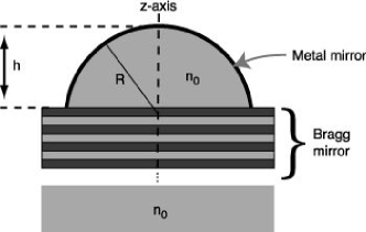
The cavity geometry is shown in Fig. 1. It is useful to define a cylindrical coordinate system (, , ) with being the symmetry axis. The height of the dome above the Bragg mirror, and its (not necessecarily constant) radius of curvature, , determine the type of modes the cavity can support. For definiteness, in this work the bulk of the dome and the space outside of the structure have refractive index . In the numerical results shown below, we will adjust the the Bragg stack design such that its stop band is centered at the modes of interest. The DBR layer structure begins with a spacer layer of optical thickness and refractive index , followed by quarter-wave layer pairs of refractive index , . Our main goal is to demonstrate the importance of the polarization-dependent phase shifts induced by this mirror in determining the resonator modes. Therefore, we also performed comparative calculations with the Bragg stack replaced by a conducting surface. In accordance with this main goal of the present study, absorption in the metal surfaces was neglected. Below, the curved mirror will be taken to be a spherical shell of constant . However, we have also carried out calculations for domes in the shape of a rotational paraboloid, to compare with earlier calculations based on a separation of variables that is possible for that system [4] when only scalar fields are considered. At size parameters between , and using only metal mirrors, all modes agreed in their spectral positions to better than five decimal places, despite the very different computational approach used in the present work.
3 Vector fields in the dome resonator
We are looking for the divergence-free, monochromatic () electric fields satisfying the vectorial wave equation. Using the axial symmetry, the field components , and can be assumed to have a -dependence of the form . For fixed azimuthal mode number , the electric field transverse to the axis, , can be decomposed into circularly polarized components using
where
| (1) |
With this, one has
| (2) |
The standard conducting-mirror boundary conditions on the curved dome (, ), together with the planar mirror at the base of the dome, generally couple , and . All modes can be labeled by , and the substitution (for ) leads to a degenerate mode. In presenting results later on, there is no loss of generality if is assumed.
As was found in [4], focusing on the axis is most pronounced for the states of the cavity in which either the magnetic or the electric field is polarized exlusively in the azimuthal direction . If , then has components only along and .
4 All-metal cavity
In a recent free-space beam experiment [7], extremely strong focusing was indeed observed with light having this type of polarization; the beam was called “radially polarized”, but a significant contribution to the focused spot actually comes from . The analogue of this for our dome cavity is illustrated in Fig. 2, assuming the flat mirror to be a conductor 111In all wave plots that are shown, we set or and take the real parts of the electric fields. . In the hemispherical limit, this mode evolves smoothly into an even more strongly focused electric multipole with and .
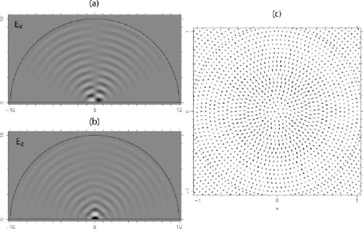
In the generic cavity with , any given mode will have admixtures of many multipoles with different , both of electric and magnetic type. The azimuthal mode number is a fixed parameter in the calculation. To obtain Fig. 2, the coefficients of this basis expansion are determined from a linear system of equations set up by the boundary conditions. The number of unknowns is determined by the number of different in the expansion. Here, , and an approximate cutoff is given by the semiclassical limit where is the maximum radial extent of the dome. Since we are interested in cavity modes, there is no incoming wave outside the dome, and the resulting system of equations is initially homogeneous. Our method proceeds by adding a further “seed” equation that sets a certain linear combinations of unknowns equal to one [8], thus converting the problem into an inhomogeneous matrix equation where the matrix depends on , and because of the seed condition. The boundary conditions are enforced by point matching (real-space points on the curved mirror, and -space points for the planar mirror), and the wavenumbers of the cavity modes are found by minimizing the residual as a function of . Details of the numerical method are presented in [9]. Before discussing the additonal complications posed by a dielectric stack mirror, we use the all-metal cavity to further investigate the effect of the dome-shaped mirror.
5 Relation to ray dynamics and confocal limit
A global picture of the possible cavity modes can be obtained from geometric optics. Mirror configurations with are called stable because they support modes centered on stable axial rays, while creates a confocal geometry if one unfolds the cavity about the planar mirror [4] (one might alternatively refer to as the “semi-confocal” condition, but ray-optically there is no difference to a symmetric, confocal mirror arrangement). This marginally stable limiting case features highly focused but non-paraxial modes. Non-paraxial ray orbits that can support cavity modes are also found for , and an efficient tool to reveal all the coexisting types of stable mode patterns is the Poincaré surface of section[4].
The axial symmetry of the cavity implies that any given ray trajectory , where is the path length, can be parametrized by an equation of the form with a vector that changes upon reflection at the boundaries but whose component is a constant of the motion (the skewness of the rays). Thus labels families of rays, and fundamental Gaussian-beam type modes are built on rays with . However, even when is fixed, stable periodic ray orbits with a multitude of different topologies will generally be found.
Regarding the internal ray dynamics, the dome cavity is thus closely related to axially symmetric spheroidal resonators, such as droplets and microspheres [10], for which the confocal limit corresponds to perfect sphericity. This analogy extends to the occurence of whispering-gallery type patterns and their non-perturbative breakup under shape distortion, which has recenty been observed in fused-silica microspheres [11]. As an illustration of this phenomenology in a dome cavity, Fig. 3 shows a cavity with , . The rectangular ray pattern in (a) for can be thought of as a stabilized periodic whispering-gallery trajectory.
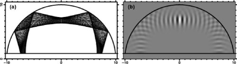
A corresponding solution of the vectorial wave equation is shown in Fig. 3 (b), indicating that the potential for strongly focused modes in near-confocal cavities comes at the price of an increased variety of off-axis modes which need to be characterized in order to choose the optimal design. It is conceivable that such new mode patterns are in fact desirable for certain applications. In order to take advantage of this new variety of modes, it will be important to combine 3D cavity shape design with suitably tailored Bragg mirrors that discriminate against the unwanted type of modes. For paraboloidal domes, some initial exploration of this aspect has been performed[4], in particular applying ray-optic phase space analysis to the problem of angle-dependent Bragg mirror transmission.
6 Relation to the paraxial approximation
However in the remainder of this paper, we turn our attention to the more conventional modes centered on the axis. These can be understood in terms of Gaussian beams when the paraxial parameter , where is the the Rayleigh range and is the beam waist radius [12]. An expression for the transverse field at a fixed in terms of the vector Laguerre-Gaussian basis can be written in analogy to (2),
| (3) |
Here, and are amplitude coefficients, the scalar Laguerre-Gauss functions have a dependence , and is the order of the Laguerre-Gauss beam, . This definiton is related to a convenient normalized expression available in the literature [13] by (we have for fixed ). The special choice is also possible, provided ; in this case, admissible solutions must have if , or if , so that has circular polarization. As a consequence, free-space LG solutions at given with order are nondegenerate. For all other orders (and any ), the two terms in (3) are degenerate free-space solutions in the paraxial approximation, and will remain nearly degenerate in a paraxial cavity. The polarization properties of the mode are fixed by the way in which the boundary conditions split this doublet (for ).
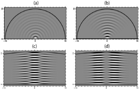
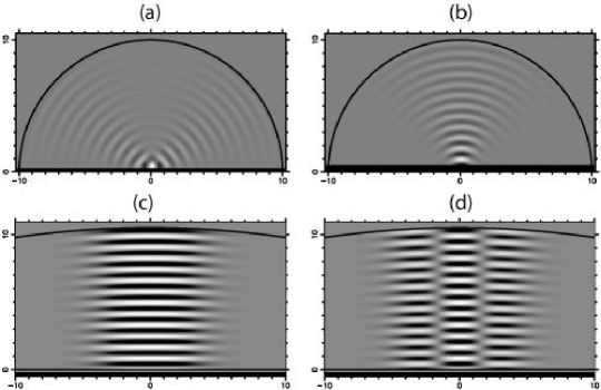
The fundamental Gaussian modes of the dome can be obtained by setting and . The spatial dependence is then , which is also called a mode. Figures 4 (a) and (b) show how the resemblance to this Gaussian mode emerges starting from the hemispherical limit.
Raising in increments of makes higher transverse excitations of the Gaussian mode accessible. This is again borne out by the numerical vectorial solutions, as shown for in Fig. 4 (c) and (d). These modes are well described by (3) with and either (c) or (d). Note that the all-metallic boundary conditions have uniquely fixed the polarization of the modes in Fig. 4 to be circular, i.e. only one of the terms in (3) is present in all cases shown up to this point, and the degeneracy in is lifted by a small but finite amount.
7 Combining metal dome and Bragg mirror
The previous results raise the question if all cavity modes of the axially symmetric dome necessarily factor into a unique polarization vector multiplied by a spatial wave function, thus making the wave problem essentially scalar. We will demonstrate below that this is not the case when a Bragg stack replaces the planar metal mirror at the base of the dome. To this end we first discuss the necessary extension of the numerical method based on the basis expansion of Section 4, allowing us to treat the combined problem of metal dome and dielectric mirror without approximations.
The complex reflection amplitude of an arbitrary planar Bragg grating is calculated with the transfer matrix method [14] and can be written in the plane-wave basis as a function of polarization, wavelength and angle of incidence, . Here, subscripts and distinguish between polarization perpendicular and in the plane of incidence. Because of this simplicity, one may decide to solve the whole dome problem in a discretized plane wave basis, which after symmetrization according to the axial rotation invariance leads to expansions of all vector field components in Bessel beams. Their (scalar) form in the dome region is
| (4) |
where is a parameter that specifies the cone of plane waves from which this beam is constructed.
However, the approach we follow in this paper is to combine Bessel waves and multipoles. We use the to describe the DBR mirror, because reflection amplitudes for a Bessel beam of given are identical to those of a plane wave at that same incident angle, . But we retain multipoles as the basis in which to specify the dome boundary conditions, because these basis functions evolve into the true cavity modes in the limiting case of the all-metal hemisphere. We discuss elsewhere [9] the relative merits of this approach compared to the procedurally more direct method of using a single basis for the entire domain. Our two-basis method makes it necessary to (i) discretize the cone angles used in the expansions, and (ii) to implement a transformation between multipoles and plane waves so that we effectively obtain a formulation of the Bragg reflection in the multipole basis.
With these modifications, the solution algorithm is the same as described for the all-metal cavity in Section 4. An important additional piece of information that enters for the Bragg-bounded dome is the -factor of the modes: if the Bragg reflectivities are not of modulus one, there is leakage loss which makes the modes metastable; to find these modes, their wavenumbers are now allowed to be complex [15]. In the following we consider only modes calculated to have , but omit a more detailed discussion of the -factors because that will require addressing the competing absorption losses in the curved metal mirror as well.
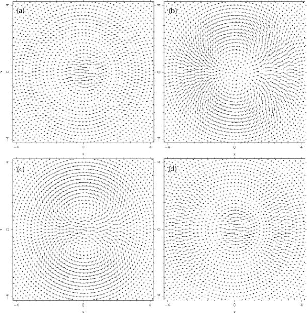
Figure 5 lists a set of results analogous to the ones shown in Fig. 4, but now including the effect of the Bragg mirror. There is no significant distinction between the two systems from a purely ray-optic point of view, and the modes in parts (a,b) of Figures 4 and 5 were obtained in the same way, by adiabatically following a fundamental Gaussian mode from small to large . Nevertheless, the near-hemispherical mode of Fig. 5 (a) exhibits a V-shaped distribution in which is absent for all-metal mirrors. We have found the same behavior in cavities as large as , . The mode is predominantly s-polarized, and its formation can be interpreted as a consequence of the fact that the Bragg reflectivity has a phase that depends on angle of incidence; in this sense, this phenomenon is induced by the Bragg stack, but arises essentially as a scalar wave effect [9].
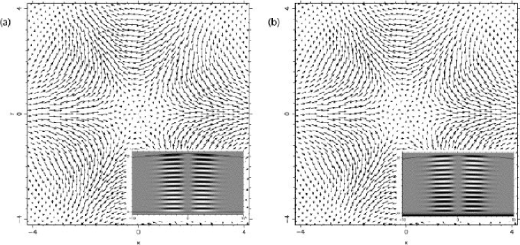
The vector nature of the electromagnetic field enters in a more intricate way if we compare the modes shown in Fig. 5 (c), (d) to the corresponding ones in Fig. 4 (c), (d). For this cavity shape, all modes shown are well approximated by Eq. (3) with and . However, whereas or in Fig. 4, we now find in both members of the doublet. Since the spatial dependence of and is different, polarization and orbital part of the wave are entangled in the sense that it is impossible to factor out a uniform polarization vector.
The difference between the side views in Fig. 5 (c), (d) and Fig. 4 (c), (d) is due to the fact that the spatial mode profiles in the dome with Bragg stack more closely resemble Hermite-Gauss beams[13], . This can be reconciled with Eq. (3) by noting that both and have projections onto and .
However, a transverse cross section of the mode field reveals the entanglement of polarization and spatial structure in these modes, which is not obvious from the side views alone. In Fig. 6, we compare the paraxial modes from Figs. 5 and 4 with respect to the instantaneous projections of the mode field into a horizontal plane. Because Eq. (3) is approximately valid, one can in fact construct [9] both (c) and (d) by appropriately superimposing the circularly polarized fields (a) and (b). Neglecting the components of the electric field, the resulting modes in Fig. 6 (c) and (d) are close to circular polarization near the axis, but generally exhibit varying polarization over the cross section. The vortex pair bracketing a central high-field region in Fig. 6 (c) corresponds to a ring of radial (linear) polarization when the time dependence of the wave is taken into account.
It is remarkable in the Bragg-mirror dome that the particular transverse polarization patterns in Fig. 6 (c), (d) are in fact robust over a large range of cavity shapes and also quite insensitive to the spectral location of the mode within the stop band of the Bragg mirror.
The Laguerre-Gauss modes responsible for the persistent mixing with polarization structure given by Fig. 6 (c), (d) have order . For completeness, we verify that the other remaining mode of order , which has , does not undergo the same qualitative transition when changing from metal to Bragg mirror. The reason is that in this case and thus there is no doublet from which superpositions can be formed. The circularly polarized singlet modes of the paraxial dome remain circularly polarized independently of the nature of the planar mirror. This is shown in Fig. 7.
8 Conclusion
There exists a great wealth of other stable but non-paraxial modes in the dome cavity with , which can be classified with the help of ray-based methods as exemplified by Fig. 2. The exact numerical calculations demonstrated in the present work are relevant to such quasiclassical studies because we are able to treat realistic cavities whose size is large in relation to . Future work in this direction will in particular have to address complex boundary conditions as they arise when different types of mirrors make up the 3D cavity. In our case, a combination of conducting surface and dielectric multilayers is considered.
The vectorial nature of the cavity fields is essential in this system. Fully vectorial mode calculations of the type performed here indicate that one of the effects induced by a Bragg-stack is the persistent mixing of doublets illustrated in Fig. 6. The nonuniform polarization patterns can be further analyzed, in particular regarding the locations of their singularities: in the near-paraxial situation, we pointed out the occurence of linear polarization on rings surrounding the circularly polarized beam axis. These considerations are of significance in particular when the coupling between cavity field and dipole emitters at the base of the dome is considered [4].
Although we presented only results for dome mirrors in the form of a conducting spherical shell, other shapes such as paraboloids can be treated. By making contact with various limiting cases in this paper, the general numerical techniques have been validated. A more detailed discussion of the numerical methods and their implementation can be found in a forthcoming publication[9].
ACKNOWLEDGMENTS
This work was supported by NSF Grant ECS-02-39332.
References
- [1] F. M. Matinaga, A. Karlsson, S. Machida, Y. Yamamoto, T. Suzuki, Y. Kadota, and M. lkeda, “Low-threshold operation of emispherical microcavity single-quantum-well lasers at 4 k,” Appl. Phys. Lett. 62, pp. 443–445, 1993.
- [2] M. Aziz, J. Pfeiffer, and P. Meissner, “Modal behaviour of passive, stable microcavities,” Phys. Stat. Sol. (a) 188, pp. 979–982, 2001.
- [3] T. M.Stace, G. J. Milburn, and C. H. W. Barnes, “Entangled two-photon source using biexciton emission of an asymmetric quantum dot in a cavity,” Phys. Rev. B 67, p. 085317, 2003.
- [4] J. U. Nöckel, G. Bourdon, E. L. Ru, R. Adams, J.-M. M. I. Robert, and I. Abram, “Mode structure and ray dynamics of a parabolic dome microcavity,” Phys. Rev. E 62, pp. 8677–8699, 2000.
- [5] V. Bulovic, V. G. Kozlov, V. B. Khalfin, and S. R. Forrest, “Transform-limited, narrow-linewidth lasing action in organic semiconductor microcavities,” Science 279, pp. 553–555, 1998.
- [6] S. Coyle, G. V. Prakash, J. J. Baumberg, M. Abdelsalem, and P. N. Bartlett, “Spherical micromirrors from templated self-assembly: Polarization rotation on the micron scale,” Appl. Phys. Lett. 83, pp. 767–769, 2003.
- [7] R. Dorn, S. Quabis, and G. Leuchs, “Smaller, sharper focus for a radially polarized light beam,” Phys. Rev. Lett. 91, p. 233901, 2003.
- [8] J. U. Nöckel, PhD thesis, Yale University, 1997.
- [9] D. H. Foster and J. U. Nöckel, “Methods for 3-d vector microcavity problems involving a planar dielectric mirror,” Opt. Commun. 234, pp. 351–383, 2004.
- [10] A. Mekis, J. U. Nöckel, G. Chen, A. D. Stone, and R. K. Chang, “Ray chaos and q-spoiling in lasing droplets,” Phys. Rev. Lett. 75, pp. 2682–2685, 1995.
- [11] S. Lacey, H. Wang, D. Foster, and J. Nöckel, “Directional tunnel escape from nearly spherical optical resonators,” Phys. Rev. Lett. 91, p. 033902, 2003.
- [12] A. E. Siegman, Lasers, University Science Books, Sausalito, CA, 1986.
- [13] M. W. Beijersbergen, L. Allen, H. E. L. O. van der Veen, and J. P. Woerdman, “Astigmatic laser mode converters and transfer of orbital angular momentum,” Opt. Commun. 96, pp. 123–132, 1993.
- [14] P. Yeh, Optical waves in layered media, Wiley, New York, 1988.
- [15] J. U. Nöckel and R. K. Chang, “2-d microcavities: Theory and experiments,” in Cavity-Enhanced Spectroscopies, R. D. van Zee and J. P. Looney, eds., Experimental Methods in the Physical Sciences 40, pp. 185–226, Academic Press, San Diego, 2002.