A scintillator tile-fiber preshower detector for the CDF central calorimeter
Abstract
The front face of the CDF central calorimeter is being equipped with a new Preshower detector, based on scintillator tiles read out by WLS fibers. A light yield of about 40 pe/MIP at the tile exit was obtained, exceeding the design requirements.
1 INTRODUCTION
The physics program at the Fermilab Tevatron Collider will continue to explore the high energy frontier of particle physics until the commissioning of the LHC at CERN. The luminosity increase provided by the Main Injector requires upgrades beyond those implemented for the first stage of the Tevatron’s Run II physics program.
The upgrade of the CDF calorimetry includes: (i) the replacement during the Tevatron shutdown in Fall 2004 of the slow gas detectors - Central Preshower (CPR) and Central Crack (CCR) detectors - with a faster scintillator version which has a better segmentation, and (ii) the addition of timing information to both the Central and EndPlug electromagnetic calorimeters to filter out cosmic ray and beam related backgrounds.
This contribution focuses on the new Preshower detector, based on 20 mm thick scintillator tiles, with a finer segmentation than the calorimeter towers, read out by a wavelength-shifting (WLS) fiber loaded into a groove on the surface of each tile. It also discusses briefly the replacement of the CCR with 5 mm thick scintillator tiles (read out with the same technique) behind a tungsten bar in order to cover the uninstrumented azimuthal regions of the central calorimeter. Each WLS fiber is spliced to a clear fiber after exiting the tile. To optimize the final design parameters we performed several tests comparing different scintillators, fibers and groove shapes.
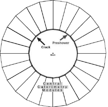
The location of the new detectors on the front face of the central calorimeter, where they will sample early showers and cover the -cracks between calorimeter wedges, is shown in Fig. 1. The CPR uses the solenoid coil and the tracking material as a radiator.
The upgrade of the CDF Central Calorimeter is expected to play important roles in Run II physics, such as soft electron tagging of b-jets, photon identification (ID) in SUSY events or other new physics, and improving jet energy resolution.
The CPR has been extensively used in electron ID, providing about a factor 2-3 more rejection of charged pions that pass all other cuts. This extra rejection has been crucial in soft electron ID for b-jet tagging, as was shown in the first top evidence paper [1]. The CPR has been used in several publications involving photon ID. By using conversion rates, which are energy independent, it extended the QCD measurement of direct photons by more than 100 GeV in photon transverse momentum [2].
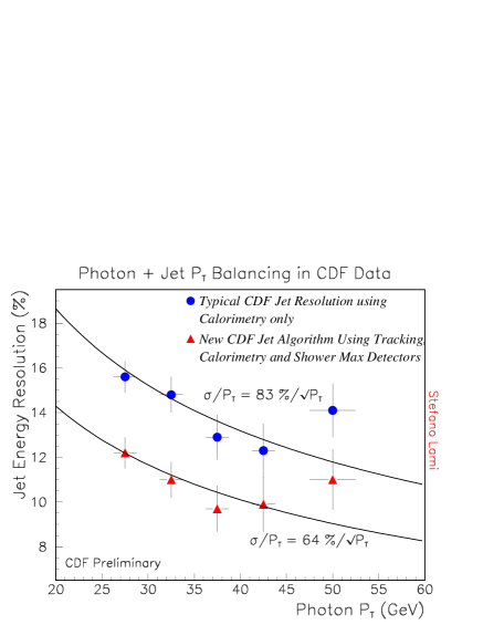
The new CPR will also be used to improve the jet energy resolution by both correcting for energy loss in the dead material in front of it and adding its information in jet algorithms incorporating charged tracking. A Particle Flow Algorithm (PFA) that combines calorimetric information with tracking and shower max detector data was tested on a Run I photon-jet data sample and provided a 20% improvement in jet energy resolution [3] (see Fig. 2).
The CCR, located after 10 radiation length thick tungsten bars, has been checked for large pulse heights in all the rare events CDF has observed in Run I. The -cracks cover about 8% of the central detector, and in events with multiple electromagnetic objects, the possibility of one object hitting the crack is substantial.
2 DETECTOR DESIGN
The new CPR will be based on 2 cm thick scintillator tiles segmented in and and read out by a 1 mm diameter WLS fiber located inside a groove on the surface of each tile. Six tiles (12.5x12.5 cm2 each) will cover the front face of each calorimeter tower, assembled in 48 modules (Al shells) as shown in Fig. 3, covering the 48 central calorimeter wedges. On exiting the tiles, the WLS fibers will be spliced to clear fibers, which will terminate into plastic connectors at the higher edge of each module. There, optical cables 5 m long will transmit the light to 16-channel Hamamatsu R5900 PhotoMultiplier Tubes (PMTs) at the back of the wedge.
The new CCR will use the same technique but the available space limits the scintillator thickness to 5 mm. Ten tiles, 5 cm wide, will cover each -crack with the same calorimeter segmentation of 10 towers/wedge.

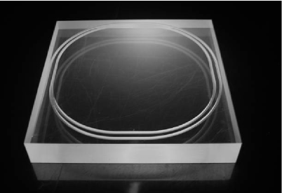
Figure 4 shows a CPR tile with a spiral groove path for the WLS fiber. To see minimum ionizing particles (MIPs) in the CPR, we request at least 5 photoelectrons (pe) at the PMT, which means at least 12 pe at the tile exit, after taking in account a 60% signal loss due to light transmission by fiber splicing and optical connector plus the clear fiber attenuation length.
3 RD RESULTS
A cosmic ray test of individual tiles inside a light-sealed box was performed in order to compare different scintillators (Bicron 408 and scintillator tiles provided by the CDF JINR Dubna group), multiclad WLS and clear fibers (Kuraray and Pol.Hi.Tech), reflectors (Al foil, Tyvek paper, 3M VM2002 reflector), and to optimize the design of the groove in the tile.
We studied the optical coupling between the fiber and the groove, and obtained similar results with either Bicron BC-600 glue or BC-630 grease, about 40% more light yield than just air coupling in a configuration with a groove of square cross section and several loops of WLS fiber.

We compared Dubna and Bicron 408 scintillators for different configurations and always obtained a similar response within 5% (see Fig. 5). We therefore opted for the less expensive Dubna scintillator. For each test we took the most probable value of a fit to a Landau distribution as the pe/MIP light yield of our measurement.
Both response uniformity (better than 3%) and light yield of tiles were found equal within errors for two kinds of groove path, circular or sigma (), passing 5 mm from the tile edges and having a radius of 5 cm at the corners. A spiral -groove was chosen, as shown in Fig. 4.
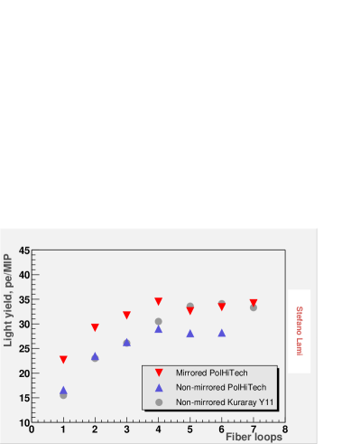
We studied two different groove cross sectional shapes. Originally the baseline design was based on a square cross section, 6 mm deep, loaded with 4 or 5 glued loops of WLS fiber. Recently, the design was changed to a keyhole shape groove with air coupling, which performed equally well with a 2-loop spiral, as seen in Fig. 4. For the interested reader, Fig. 6 shows the result of our study on the optimal number of fiber loops into a -groove with a square cross section - 8 mm deep for this particular test. For Pol.Hi.Tech fibers the light yield reaches a plateau at N4 loops, after which the gain of a bigger sampling seems to be compensated by the attenuation of the longer fiber. For a Kuraray Y11(250) fiber, whose attenuation length is about 50 cm longer than Pol.Hi.Tech or about one extra loop, the plateau is reached at N5 loops.
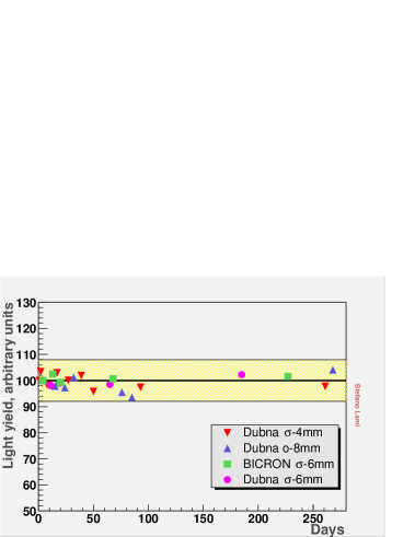
The concern about glue damaging fibers prompted us to study the response of different glued tiles over a period of 9 months. No time decay was observed, as shown in Fig. 7. However, to reduce assembly time and remove any concern about gluing, we decided to use a keyhole groove (1.8 mm deep) where no glue is needed to hold the fiber.

In Fig. 8 the light yield from a 2-loop spiral keyhole groove with air coupling (solid histogram and fit) is compared to the light yield from 4 glued fiber loops in a 6 mm deep square cross sectional groove (dash-dotted histogram). Both methods give a similar result, 15% more light than 1 loop of keyhole groove (dashed histogram). In this test Tyvek paper and a mirrored Pol.Hi.Tech fiber were used. The keyhole cross section, with a diameter of 1.2 mm, seems to serve as an extra cladding to better trap the light lost by the fiber. The spiral is limited to 2 loops, with outer (inner) radius of 5 (4.5) cm, to mantain the fiber curvature above a radius of 4 cm, critical for fiber stress. With this design we obtained 38 pe/MIP in the best configuration with air coupling (test 7 in Tab. 1).
| Test | Fiber into spiral | Mirror | Reflector | pe/MIP |
|---|---|---|---|---|
| 1 | Pol.Hi.Tech | No | Tyvek | 24.1 |
| 2 | Pol.Hi.Tech | Yes | Tyvek | 29.4 |
| 3 | Kuraray Y11(250) | No | 3M | 28.1 |
| 4 | Kuraray Y11(250) | Yes | Tyvek | 30.5 |
| 5 | Kuraray Y11(350) | No | Tyvek | 28.7 |
| 6 | Kuraray Y11(350) | No | 3M | 32.9 |
| 7 | Kuraray Y11(350) | Yes | 3M | 38.2 |
| 8 | Kuraray Y11(350)+Grease | Yes | 3M | 43.9 |
The study of the best configuration with a 2-loop spiral keyhole groove in a Dubna tile is summarized in Tab. 1. We obtained a similar light yield with either Pol.Hi.Tech or Kuraray Y11(250) fibers, but Kuraray Y11(350) were about 17% better (test 6 vs. test 3). The 3M reflector increased the light yield by 15% relative to Tyvek and provided good uniformity. Aluminizing the end of the fiber left inside the tile makes an important difference, 20% more light in the 2-loop spiral. While test 7 is our final choice, we also tested that filling the keyhole groove with grease would increase the light yield to 44 pe/MIP, 15% more than air coupling.
Given the narrow width of 5 cm for the CCR tile, a mirrored Kuraray Y11(350) fiber will be loaded into a straight groove. We obtained 7 pe/MIP (the tile is 5 mm thick), which is acceptable as we will measure electromagnetic showers in the central calorimeter azimuthal cracks.
4 CONCLUSIONS
The CDF experiment is undergoing an upgrade of the central calorimeter in order to mantain and extend the Run I capabilities. Design choices have been made to minimize cost and technical risk. The light yield obtained exceeds the original design requirements.
At the time of writing, the assembly of the final CPR modules is under way and preliminary tests show an average light yield of 16 pe/MIP at the PMT (after the whole optical chain, including 5 m of clear fiber), consistent with a light yield of 40 pe/MIP at the tile exit. The new CPR and CCR detectors are to be installed on the front face of the central calorimeter during Fall 2004.
References
- [1] F. Abe et al., Phys. Rev. Lett. 73 (1994) 225.
- [2] F. Abe et al., Phys. Rev. D 48 (1993) 2998; Phys. Rev. Lett. 73 (1994) 2662.
- [3] S. Lami et al., Proc. of IX Int. Conf. on Calorimetry in High Energy Physics (Calor2000), 555.