Efficient excitation of cavity resonances of subwavelength metallic gratings.
Abstract
One dimensional rectangular metallic gratings enable enhanced transmission of light for specific resonance frequencies. Two kinds of modes participating to enhanced transmission have already been demonstrated : (i) waveguide modes and (ii) surface plasmon polaritons (SPP). Since the original paper of Hessel and Oliner hessel pointing out the existence of (i), no progress was made in their understanding. We present here a carefull analysis, and show that the coupling between the light and such resonances can be tremendously improved using an evanescent wave. This leads to enhanced localisation of light in cavities, yielding, in particular, to a very selective light transmission through these gratings.
pacs:
71.36.+c,73.20.Mf,78.66.BzThe practical importance of the optical properties of metallic gratings, is no more to underline barnes . Many important applications were found in several fields of science, and are today extensively used in many kinds of sensors and actuators. Recently, a further property of gratings was found by Ebbesen et al. ebbesen : the discovery of an optical transmission phenomena observed in two-dimensional arrays of subwavelength holes perforated in a thin metallic plate, which led to important theoretical works porto ; moreno ; takakura ; cao ; lalanne . That experiment is however in a large extend physically equivalent to a previous one reported by Dragila et al.dragila . These authors showed that a thin metallic opaque plate - without any holes - can transmit light, provided that it is enlightened by an evanescent wave generated by total reflection in a prism. For both experiments, i.e. Dragila et al. or Ebbesen et al., the physics is almost the same. In effect, to excite a surface plasmon on a flate metallic surface, the incident wave must have a wavevector component parallel to the surface larger than , being the wavevector of the incident light, and the incidence angle. There are two possible ways to do that: by changing the parallel component of the wavevector into a pseudo-wavevector , where is a positive or negative integer, and the period of the holes (case of a perforated plate ebbesen ); or by using an attenuated total reflection (ATR) experiment otto . The increase of the parallel wavevector component is thus provided by the total reflection on a prism from which an evanescent wave emerges. In both cases, the surface plasmon polaritons (SPP) of the external interfaces can be excited. However, another condition is needed to have transmission through the plate: SPP on both sides must be coupled. In the case of perforated surface, it is essentially the evanescent field in the holes which mediates the coupling, while in the case of ATR, evanescent waves inside the metal directly couples the plasmons of both interfaces. As was pointed out in barbara1 , for two dimensional subwavelength holes, the field in the cavities is always evanescent, so that the coupling, and thus the efficiency of the transmission, is bounded by the thickness of the plate: a too thick plate perforated with subwavelenth holes would transmit almost nothing. It is the same in the case of ATR experiment where the efficiency of the coupling is limited by the field decay in the metal, linked to the skin depth.
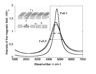
Such a thickness limitation may not exist for one-dimensional periodically structured film as those sketched on the inset of fig.1. It was effectively shown experimentally and theoretically porto ; barbara1 ; barbara2 that a second mechanism is important : the light can be transmitted by excitation of one of the waveguide modes of the slits of the gratings (different than SPPs). Indeed, in this geometry (rectangular slits), and with a -polarized incident wave i.e. magnetic field along the -axis, the grating supports modes that propagate into the slits along the -axis, even when these have a subwavelength width , and whatever their thickness is barbara1 . However, the transmission by such a mechanism is poorly selective and the waveguide resonance spectral width is large barbara1 . In the infrared region, a half-width of about was reported for a resonant transmission close to 0.4 occuring at barbara1 . Recently, using the same rectangular geometry, but with a more complicated architecture made of one single slit close to several other grooves, Martin-Moreno et al. garcia1 succeeded to improve the efficiency of the transmission through the slit by combination of different geometrical parameters which allowed coincidence of several waveguide resonances.
Waveguide modes of subwavelength metallic gratings in deep structured surfaces, predicted by Hessel and Oliner hessel , was experimentally observed later lopez . The ordinary theory of cavity resonators (see jones for instance) tells us that for any closed metallic cavity, i.e. a connected volume, there are proper modes which can carry high electromagnetic field. However, the resonance is bounded by the absorption of the metallic walls of the cavity which leads to a finite width in the resonance peaks also called Q-factor. If the optical absorption is weak, as it is the case for gold in the infrared, the resonances remain very narrow and well-defined. Another damping mechanism appears when a hole is made in the cavity, taking solely its origin in the geometry. In other words, the real wavevectors of the eigenmodes of a perfectly conducting closed cavity becomes complex by the opening of a hole with a finite size. This is exactly what happens in deeply structured gratings where the slits play the role of the hole cited above and therefore waveguide resonances of gratings (even perfectly conducting) have complex wavevectors as was previously pointed out in hessel . When they are excited by a radiating incident wave whose wavevector is real, it can not perfectly match with the complex one of the eigenmode and the resonance is a forced one. On the opposite, we expect a higher Q-factor when exciting the waveguide resonance with a complex wavevector obtained from an ATR configuration.
Let us examine these two cases from a simplified theoretical point of view. We consider a grating with geometrical parameters , and (see fig. 1) enlightened (close to the surface) with a -polarized incident wave . Due to the Helmoltz equation (in the air), . One can choose without any loss of generality . Now, if , we have a propagating incident wave with a real wavevector, while if , we have an evanescent field with complex wavevector. Within the modal method, used for the calculations and fully described elsewhere wirgin ; barbara2 , it is easy to show that, in case of subwavelength slits (), the magnetic field in the slits is proportional to , given by
| (1) |
where , is a geometrical factor of the gratings, and and with running from to . and are thus the wavevector coordinates of the reflected order. Waveguide resonances occur at the minima of . These are approximately reached when satisfies and the width is then proportional to wirgin . Writing and after some elementary algebra, the equation yields to:
| (2) |
which can be easily satisfied by choosing a correct parameter, as and do not depend on its value.
When equ.(2) is satisfied, the imaginary part becomes: . In order to highlight solely the resonance phenomena linked to the waveguide modes, we consider all along this paper a spectral region where no SPP can be excited ()barbara1 . In that case, for any , all and are pure imaginary numbers. When the incident wave is propagating, and is real so that . The width of the resonance has thus a finite value depending on the geometrical parameters of the grating: . This is shown on figure 1 where the intensity of the magnetic field inside the groove at a waveguide resonance is represented. This reasoning is made for perfectly conducting gratings. Including a small absorption in the metal does not quantitatively change a lot the result as can be seen in figure 1. If, now, , the incident wave is evanescent since becomes imaginary Consequently, and thus both vanishe at the resonance. This is the point we want to highlight in this letter: an evanescent incident wave would excite much better the waveguide mode of the grating.
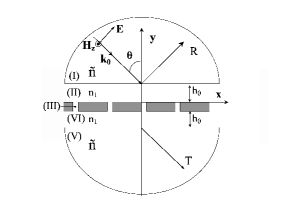
To illustrate this point, we examine the case of a grating illuminated by evanescent wave, coming from an ATR configuration as sketched on figure 2. A first (hemi-cylindrical) prism is positioned above the grating to create the evanescent incoming wave while the second one plays the opposite role, converting the evanescent transmitted field into a propagating one. Both prism have a high refractive index corresponding to that of the Germanium in the infrared handbook and are at a distance from the grating considered to be a purely gold structure imbedded in air (). Following the modal expansion method barbara1 ; barbara2 ; wirgin , the space is divided into five regions: regions (I) and (V) are the prisms, (II) and (IV) are the air and (III) is the empty region (air) of the grating, where the magnetic field is expanded as:
| (3) | |||||
In each region of space, the field satisfies the Helmholtz equation, such that whatever (I)-(V), and for all , . Moreover, , and . The expression of the field in (III) is given only taking into account the first term of a more general expansion, which is a very good approximation in the case where barbara2 . The amplitudes of the field in the grooves and as well as the reflection and transmission coefficient are calculated by applying the usual boundary conditions barbara1 :
with
with where is the metal dielectric constant (the limit for a perfectly conducting material is obtained by taking ). The terms and are expressions given by:
where and .
The zero-order transmission coefficient is then:
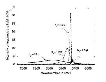
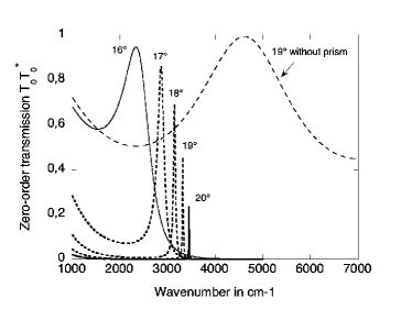
To have a total reflexion at the interface (I)/(II), we consider an angle of incidence which satisfies . Under such condition, all the different orders of the field in region (II) and (IV) are evanescent since are pure imaginary numbers whatever is. Let us first examine the assymptotic case , which clarifies the general trend of the system. Just at the resonance, one can show after some algebra (linear expansion in which is small) that for large enough , the modulus of reduces to , where means ”quantity of order of ”. Subsequently, the field in the groove behaves as : , while the zero order transmission coefficient . By noting the difference of factor in the exponential terms ( and ), one immediately sees that for a perfect metal, i.e strictly, the width of the resonance tends to zero as (recall that ). In the same time, the field in the groove exponentially increases, while the transmission tends to 1 just at the resonance frequency and to zero elsewhere. For a real metal, i.e with finite (even very small) , there is a qualitative change. First, the width of the resonance is bounded, and tends to a very small, but finite value . In that case both the field and the transmission vanish owing to the exponential factor in the numerator. All these statements, can be understood physically : as becomes larger, the number of photons which arrives on the grating exponentially vanishes. If there is no absorption at all, the resonance can be excited, while if there is an absorption, a part of incident photons are absorbed, while the remaining ones excite the resonance. When there is no photons anymore, the resonance cannot be excited. This effect is shown on fig.3, where the resonance width is strongly reduced as expected and a maximum of enhancement of the field is observed around . For larger the field decreases as can be seen for . The same phenomena arises for the transmission which is directly connected to the field enhancement in the slits. A compromise is thus necessary between the gain in the width of the resonance, which always decreases with increasing up to its lower bound ), and the efficiency of the transmission. The angle of incidence also enters in the expression of so that the results are very sensitive to it owing to the exponential dependance of the different terms. Fig.4 shows the zero order transmission for for different angles. As can be seen, the reduction of the resonance width of the transmission is spectacular. The resonance widths obtained for , , , and , are respectively , , and , while the transmissions are maintened to high values, respectively , , , and . These kind of devices could be employed to create polarization filters with extremely narrow widths. Finally, we have shown in this paper that the cavity resonances excitation can be notably improved, yielding a strong localization of the electromagnetic field. The key point is the use of an evanescent incident wave, illustrated here by an ATR configuration. However, many other devices producing evanescent waves could also be employed to enhance the field in such cavities.
References
- (1)
- (2) A. Hessel and A.A. Oliner, Applied Optics, 4, 1275 (1965)
- (3) W.L. Barnes, A. Dereux, T.W. Ebbesen, Nature (London), 424, 824 (2003)
- (4) T.W. Ebbesen, H.J. Lezec, H.F. Ghaemi, T. Thio, P.A. Wolff, Nature (London), 391, 667 (1998)
- (5) J.A Porto, F.T. Garcia-Vidal, J.B. Pendry Phys. Rev. Lett. 83, 2845 (1999).
- (6) L. Martin-Moreno, F.J. Garcia-Vidal, H.J. Lezec, K.M. Pellerin, T. Thio, J.B. Pendry, T.W. Ebbesen, Phys. Rev. Lett., 86, 1114 (2001).
- (7) Y. Takakura, Phys. Rev. Lett., 86, 5601 (2001)
- (8) Q. Cao, P. Lalanne, Phys. Rev. Lett., 88, 057403-1 (2002).
- (9) P. Lalanne, C. Sauvan, J.-P. Hugonin, J.-C. Rodier, P. Chavel, Phys. Rev. B 68, 125404 (2003)
- (10) R. Dragila, B. Luther-Davies, S. Vukovic, Phys. Rev. Lett. 55, 117 (1985)
- (11) A. Otto, Z. Physik, 216, 398 (1968)
- (12) A. Barbara, P. Quémerais, E. Bustarret, T. Lopez-Rios, Phys. Rev. B 66, 161403(R) (2002)
- (13) A. Barbara, P. Quémerais, E. Bustarret, T. Lopez-Rios, T. Fournier, Eur. Phys. Jour. D 23, 143 (2003)
- (14) L. Martin-Moreno, F.-J. Garcia-Vidal, H.-J. Lezec, A. Degiron, T.W. Ebbesen, Phys. Rev. Lett. 90, 167401 (2003)
- (15) T. Lopez-Rios, D. Mendoza, F.J. Garcia-Vidal, J. sanchez-Dehesa, B. Pannetier, Phys. Rev. Lett. 81, 665 (1998)
- (16) D.S. Jones, The theory of electromagnetism, Pergamon Press Oxford (1964)
- (17) A. Wirgin, A.A. Maradudin, Prog. Surf. Sc., 22, 1 (1986)
- (18) E.D. Palik, Handbook of Optical Constants of Solids, Academic Press.