Secondary electron yield measurements from thin surface coatings for NLC electron cloud reduction
Abstract
In the beam pipe of the positron damping ring of the Next Linear Collider, electrons will be created by beam interaction with the surrounding vacuum chamber wall and give rise to an electron cloud. Several solutions are possible for avoiding the electron cloud, without changing the bunch structure or the diameter of the vacuum chamber. Some of the currently available solutions for preventing this spurious electron load include reducing residual gas ionization by the beam, minimizing beam photon-induced electron production, and lowering the secondary electron yield (SEY) of the chamber wall. We will report on recent SEY measurements performed at SLAC on TiN coatings and TiZrV non-evaporable getter thin films.
1 Introduction
Beam-induced multipacting, which is driven by the electric field of successive positively charged bunches, arises from a resonant motion of electrons that were initially generated by photon, gas ionization or by secondary emission from the vacuum wall. These electrons move resonantly along the surface of the vacuum chamber, occasionally getting ”kicked” by the circulating beam to the opposite wall. The electron cloud effect (ECE), due to this multipacting, has been observed or is expected at many storage rings. The space charge of the cloud, if sufficient, can lead to a loss of the beam or, at least, to a drastic reduction in luminosity. In order to minimize the electron cloud problem which might arise in the NLC, we are looking to solutions involving surface coating of the secondary electron emitting vacuum wall.
2 Experiment Description and Methodology
The system and methodology used to measure the secondary electron yield has been described thoroughly in reference [1]. The system is composed of two coupled stainless steel UHV chambers where the pressure is in the low 10-10 Torr scale in the measurement chamber and high 10-9 Torr scale in the ”load lock” chamber, Fig.1. Samples individually screwed to a carrier plate, are loaded first onto an aluminium transfer plate in the load lock chamber, evacuated to the low 10-8 Torr scale, and then transferred to the measurement chamber.
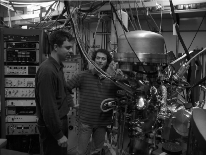
One sample at a time is measured in the measurement chamber, by placing it on a dedicated support, Fig.2. Sample temperature can be monitored by the use of two thermocouples, and chemistry by x-ray photoelectron spectroscopy (XPS). In the case of a non-evaporable getter (NEG) sample, thermal activation of the layer is provided by electron bombardment to the back of the sample.
SEY measurements were made with a Keithley 6487, a high resolution picoameter with internal 505 V supply and IEEE-488 interface. The 6487 has several filter modes which were turned off for our measurements. The integration time for each current reading is set to 167 microsec, which is the minimum value for the instrument. The current for each primary energy step was sampled one hundred times; the mean and standard deviation were returned from the picoameter to the computer.
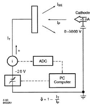
Calculation of the SEY () is done via the equation in Fig.2
where IP is the primary lectron gun current impinging on the sample and IT is the total current measured on the sample (). IS is the secondary electron current leaving the sample.
It is important to not look at the SEY at low primary energy and try to conclude something about elastic reflectivity. Data below 20 eV comes from a band structure and are a combination of diffraction from the crystalline structure and energy absorption by the material [2]. Surface effects such as roughness, angles of incidence of the primary electron and chemistry on the surface influence the SEY of a material. More details on the methodology can be found in reference [1]
3 Results & comments
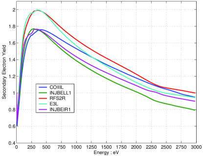
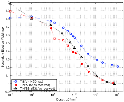
As also shown in reference [1] for TiN/Al; the SEY of TiN/SS (TiN coated on stainless steel) has a spread, see Fig.3. The process used to coat them is described in reference [3]. The spread in the can be hypothesized as depending on contamination, roughness, and nitrogen pressure [4]. Contamination and stoichiometry determination, of the samples, were obtained by XPS, cf Table.1.
| Sample | Ti At% | N At% | Contamination |
|---|---|---|---|
| INJBEIR1 | 14 | 15.4 | - |
| INJBELL1 | 20 | 23.75 | - |
| RFS2R | 14.5 | 14.9 | Sodium |
| E3L | 13.4 | 13.06 | - |
| CO111L | 16 | 14.6 | Sodium |
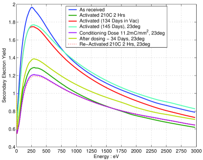
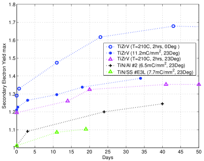
Results, for a series of processes, from a , at%, NEG coated on SS substrates are shown in Fig.4. Initially, the sample was measured ”as received”, then after a first activation at 210∘C for 2 hours. The sample is then left in the measurement chamber for 145 days at a pressure below 10-9 Torr, N2 equivalent. The system was then exposed frequently to the unbaked vacuum of the load lock chamber of a few 10-9 Torr. The next step was bombardment of the sample by electrons of kinetic energy 130 eV. Results of this electron surface conditioning are shown in Fig.5. This conditioning effect is also observed for the TiN/Al and TiN/SS samples, Fig.5. The NEG sample is then left in vacuum for 34 days before being thermally reactivated at 210∘C for 2 hours. Effects of the recontamination by this residual vacuum below 10-9 Torr on the , for the TiN and NEG samples after these different processes, are shown in Fig.6.
4 Conclusion
We have presented a brief report on the status of SEY experiments carried out at SLAC. In the case of the NEG getter coating, the influence of the activation and recontamination on its pumping action were investigated. The maximum SEY increased from 1.2 to 1.4 after forty days of exposure to a vacuum of 5.10-10 Torr. The second set of data after activation agree with CERN measurements[5]. Gas-saturated and conditioned NEG seems to not have a above 1.4. Conditioning the NEG with a 130 eV electron beam leads to a of 1.3, after a dose of 1 mC/mm2. The influence of electron conditioning has been shown for the TiN on SS or Al substrate. Values of , reached at a dose of 1 mC/mm2, are 1.1 for both samples. Recontamination does not degrade the SEY dramatically, Fig.6.
5 Acknowledgments
We would like to thank P. He and H.C. Hseuh at BNL for providing the TiN samples and C. Benvenuti at CERN for the TiZrV sample. Thanks to G. Collet and E. Garwin, SLAC, for adding the SEY capability into the XPS system.
References
- [1] F. Le Pimpec et al. SLAC TN03-052, 2003.
- [2] E. Tamura et al. Solid State Commun.55:543-547,1985
- [3] P. He et al. In PAC 2001, 2001.
- [4] H. Hseuh et al. In Electron Cloud Workshop, 2004.
- [5] C. Scheuerlein. CERN-THESIS-2002-026, 2002.