Preprint of:
Simon J. Parkin, Timo A. Nieminen, Norman R. Heckenberg,
and Halina Rubinsztein-Dunlop
“Optical measurement of torque exerted on an elongated object by
a non-circular laser beam”
Physical Review A 70(2), 023816 (2004)
Optical measurement of torque exerted on an elongated object
by
a non-circular laser beam
Abstract
We have developed a scheme to measure the optical torque exerted by a laser beam on a phase object by measuring the orbital angular momentum of the transmitted beam. The experiment is a macroscopic simulation of a situation in optical tweezers, as orbital angular momentum has been widely used to apply torque to microscopic objects. A hologram designed to generate LG02 modes and a CCD camera are used to detect the orbital component of the beam. Experimental results agree with theoretical numerical calculations, and the strength of the orbital component suggest its usefulness in optical tweezers for micromanipulation.
I Introduction
Optical tweezers trap microscopic particles using the gradient force generated by a tightly focused laser beam Ashkin et al. (1986). Angular momentum (AM) in the beam can be transferred to the trapped particle via absorption or scattering. Both spin and orbital angular momentum have been used to rotate absorbing particles He et al. (1995a); Friese et al. (1996); Simpson et al. (1997); Friese et al. (1998a). Spin angular momentum is due to the polarisation of light, and is per photon for left or right circularly polarised light Poynting (1909); Beth (1936). Angular momentum due to the spatial distribution of the light’s wavefront is called orbital angular momemtum, and is per photon, where is the azimuthal mode index Allen et al. (1992). Polarised light can be used to rotate transparent birefringent particles Friese et al. (1998b); Higurashi et al. (1998) and transparent nonspherical particles Bayoudh et al. (2003); Bonin et al. (2002); Bishop et al. (2003). In both of these cases, the torque is due to the transfer of spin angular momentum, and can be determined by measuring the degree of circular polarisation of the light once it has been transmitted through the particle in the trap Bishop et al. (2003).
Elongated particles have also been aligned through the exchange of orbital angular momentum using non-circular beams O’Neil and Padgett (2002); Santamato et al. (2002); Dasgupta et al. (2003). In this case, the gradient forces that act in optical tweezers to attract a transparent particle towards regions of high intensity act to rotate the particle so that it lies within the non-circular high intensity focal spot. The same effect can be achieved by using two independent beams to trap the ends of an elongated particle Bingelyte et al. (2003). Since this torque arises purely from the interaction between the particle and the intensity profile of the beam, and is therefore independent of the polarisation, it depends solely on the transfer of orbital angular momentum. Notably, when rotating elongated objects, this torque is much greater than that due to polarisation Bishop et al. (2003), so the use of orbital angular momentum can be highly desirable. However, to optically measure the total angular momentum transferred to the particle, the orbital component must also be measured. The measurement of this orbital component is the goal of this present work. However, to avoid the complication of a highly converging and diverging beam and microscope optics, a macroscopic experiment is performed rather than using optical tweezers. This is also desirable to avoid effects due to spin angular momentum. We simulate the alignment of an elongated object (a rod) to an elliptical beam on a macroscopic scale. The torque on the rod can then be determined by measuring the resulting angular momentum in the beam.
Laguerre–Gauss (LG) modes of laser light with a phase singularity in the centre of the beam carry orbital AM Allen et al. (1992). These modes of laser light can be made using computer generated holograms He et al. (1995b). A hologram is a recording of the interference pattern by a light field of interest with a reference beam. By calculating the interference pattern that results from a plane wave and LG mode we can make a hologram which will generate LG modes when illuminated by a Gaussian beam. The same hologram pattern that was used to make a beam with orbital AM can also be used to detect orbital AM in a beam as we will demonstrate in this paper.
Orbital angular momentum states are also of interest to the quantum information and communication fields as the infinite spatial modes offer multidimensional entanglement. Computer generated holograms have been used to generate superpositions of LG modes, and the same holograms can be used to detect these states. These schemes have been proposed to measure entanglement on the single photon level Mair et al. (2001); Leach et al. (2002).
II Theory
That light and other electromagnetic fields can carry angular momentum follows directly from the transport of linear momentum, since the linear and angular momentum flux densities and are related by
| (1) |
For electromagnetic fields, the momentum flux density is given by
| (2) |
where is the Poynting vector and is the speed of light. The coupled electric and magnetic fields form a spin-1 system, and, in general, (1) includes both a spin component, associated with the polarization, and an orbital component due to the spatial structure of the field Humblet (1943); Crichton and Marston (2000).
A monochromatic paraxial field, such as a typical laser beam, can be specified by a slowly varying complex scalar amplitude function that satisfies the scalar paraxial wave equation Siegman (1986):
| (3) |
In the paraxial approximation, the two tranverse vector components of the field de-couple, and the longitudinal component vanishes. Thus, the two linearly polarized components of the amplitude individually satisfy the scalar paraxial wave equation, and the spin and orbital angular momenta de-couple. Henceforth, we will only consider the orbital angular momentum about the beam axis, which can be found using the orbital angular momentum operator in cylindrical coordinates:
| (4) |
The Laguerre–Gauss modes Siegman (1986) form a complete orthogonal set of solutions to (3), so we can write
| (5) |
where are mode amplitudes, and
| (6) | |||||
are the normalized mode functions for Laguerre–Gauss modes LGpl of degree and order . Since the LG modes are orthogonal, the total power is given by
| (7) |
Since the mode functions are also eigenfunctions of the orbital angular momentum operator, the orbital angular momentum flux is simply
| (8) |
Notably, the orbital angular momentum depends on the magnitude of the (complex) mode amplitudes, and not their phase. The power in a particular mode also depends on the magnitude of the mode amplitude, and hence, if the modes can be separated, the orbital angular momentum flux can be determined by measurements of the power. It is not necessary to separate modes of differing radial degree , only modes of differing azimuthal order , since the ratio of angular momentum to power is the same for all modes of the same order . The modes of differing can be separated by using a hologram as an analyzer; this is discussed in the following section, III.
The mode amplitudes can also be found directly from the field, if the actual field is known. In general, this requires knowledge of the actual electric and magnetic fields, including phase information. However, since the mode amplitudes themselves are not required, but only their magnitudes, the holographic filtering we perform provides us with the necessary information.
In order to theoretically predict the torque exterted on our test object, we need to know the angular momentum fluxes of the incident and transmitted beams. The torque acting on the test object is then given by the difference in the angular momentum fluxes of the incident and transmitted beams given by (8). This requires the magnitudes of the mode amplitudes. We determine the mode amplitudes of the incident beam by measuring the aspect ratio of our elliptical incident beam at the beam waist, and assuming that we have an elliptical Gaussian beam. Thus, by assuming a constant phase across the beam in the beam waist, we have the required knowledge of the fields.
We determine the mode amplitudes by using an overdetermined point-matching method, similar to the one we have used previously for non-paraxial beams Nieminen et al. (2003). Since, for practical computational purposes, the summation in equation (5) must be truncated at a finite degree and order , we obtain, for a single point
| (9) |
For a set of points, this gives a system of linear equations from which the unknown mode amplitudes can be found. The number of points is chosen to be larger than the number of unknown mode coefficients, which is , and are then found numerically using a standard least-squares solver for an overdetermined linear system.
The use of an overdetermined system eliminates the high-spatial-frequency artifacts that would otherwise occur if only the minimum possible number of points was used. The mode amplitudes could also be found using an integral transform, but the point-matching method allows a coarse grid to be used and gives good convergence Nieminen et al. (2003).
While the incident beam mode amplitudes can be found by measuring the intensity profile of the incident beam, and assuming a constant phase in the waist plane, this assumption will not be sufficiently accurate for the transmitted beam—passage through our test object alters the phase. Instead, we calculate the complex amplitude (including phase) of the transmitted beam by treating the test object as a pure phase object of negligible thickness altering only the phase of the incident beam as it passes through (the physical optics approximation). The same point-matching method is then used to determine the mode amplitudes of the transmitted beam. Equation (8) then gives the angular momentum fluxes, and the difference between these is the torque exerted on the test object.
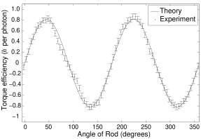
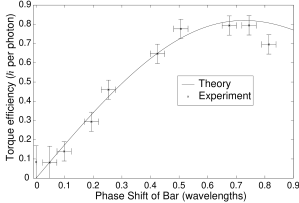
This technique is used to calculate the torque as a function of phase thickness (fig. 7) and the amplitude of the sinusoidal variation of torque with respect the angle of the rod in the elliptical beam (fig. 5).
The orbital torque can also be calculated by assuming that the elongated particle acts as a cylindrical lens Santamato et al. (2002); Beijersbergen et al. (1993); Courtial et al. (1997). It can be noted that cylindrical lenses can be used as mode converters to produce Laguerre–Gauss beams which carry orbital angular momentum, also with resulting orbital torque Beijersbergen et al. (1993); Courtial et al. (1997)
The elliptical beam is periodic in the azimuthal angle , with period . Therefore, a Fourier series expansion of the azimuthal dependence contains terms of angular frequency , where is an integer. The azimuthal term in the LG modes arises from such a Fourier expansion, and so, for an elliptical beam, or indeed any beam with an azimuthal period of , for non-zero modes. That is, only modes with even contribute. The actual distribution of power among modes of differing for the incident beam used in our calculations (a beam with an elliptical focal spot of aspect ratio 2.25, which is the measured aspect ratio of the beam used in our experiments), is shown in table 1. Almost all of the power is in modes with .
| Fraction of power | |
|---|---|
| % | |
| 6.4% | |
| 86% | |
| 6.4% | |
| % |
Since the test object we used also has a periodicity in the azimuthal angle of , only even modes are present in the transmitted beam. This can be deduced from the fact that, in the physical optics approximation, the transmitted field is the product of the incident field and a phase factor :
| (10) |
Since only the azimuthal variation affects the orbital angular momentum about the beam axis, it is sufficient to determine the frequencies present in the Fourier expansion with respect to the azimuthal angle . Since this product is a convolution in the Fourier domain, the angular frequencies present will be those present in the incident beam plus those present in the Fourier expansion of . Since both and have a period of , the convolution does not alter the angular frequencies present—the sum of two even integers is still an even integer. If we consider an incident beam that is a single LG mode, we see that the symmetric scatterer couples the incident mode to even LG modes in the transmitted beam.
This result does not depend on the physical optics approximation (which we used above), and is a quite general result relating the rotational symmetry of a scatterer with the coupling between azimuthal modes Schulz et al. (1997).
III Method
We have carried out an experiment designed to measure the orbital angular momentum component of a light beam, and from this infer the torque exerted by a light beam on an object in its path. The orbital angular momentum is detected by a hologram which generates LGpl modes (say LG0,±2 in the first order) from a Gaussian input beam. The LGpl modes have an orbital angular momentum component of l per photon Allen et al. (1992), so that an LG0,2 mode has 2 orbital angular momentum per photon. If the input beam is instead a LG0,±2 then a Gaussian is generated in one of the two first order modes in the diffraction pattern Leach et al. (2002). Therefore if the input into the hologram is some arbitrary beam, then by measuring the strength of the Gaussian at the centre of the two first diffraction orders, the orbital angular momentum carried by the LG0,±2 components of the beam can be determined. Only the Gaussian component in the first diffraction orders has a non-zero intensity at the centre of the spot. In this experiment the arbitrary beam is an elliptical beam scattered by a phase object. The phase object is a bar or rod which is at some angle to the major axis of the elliptical beam. The orbital angular momentum in this beam is a result of the various modes which compose the elliptical beam and the torque exerted on the phase object as it tends to align with the major axis of the elliptical beam. Due to the order 2 rotational symmetry of the system, the torque will predominantly be due to the modes.
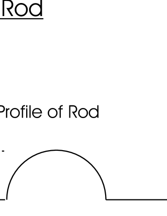
The pattern for the hologram was generated from the calculated sinusoidal interference resulting from a plane wave and a LG02 mode. This image of the pattern was printed onto film using a Polaroid ProPalette 7000 Digital Film Recorder. The film was then contact printed to a holographic plate that has a thick silver halide emulsion layer. The developed plate was bleached using mercuric chloride to produce a pattern which acts as a phase hologram. Images of bars were also made into phase objects using this same method—the phase picture of the rod was made from a grayscale image that has a circular profile (fig. 2).
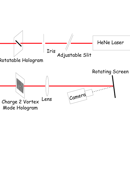
The experimental setup is shown in fig. 1. A helium neon laser beam is directed through an adjustable slit which creates an elliptical beam that is then incident on a plate. The plate can be rotated such that the phase image of a rod on the plate can be oriented at any angle with respect to the beam. The beam then passes through a second holographic plate which contains a LG02 sinusoidal phase hologram. The beam then passes through a long focal length lens and onto a rotating screen at the focal point of the lens. A CCD camera captures the pattern displayed on the screen. The position of the zero-intensity spots at the center of each diffraction order is noted when a Gaussian beam (that is, an LG00 beam) is incident on the hologram. The intensity at these locations is proportional to the power in the mode with the appropriate angular momentum. This system is calibrated by measuring the detected signal produced when the a pure LG mode of known power is incident on the analysing hologram.
To do this, the slit was removed and another LG02 hologram replaced the phase image of a rod. The first order mode from the first hologram, which has a known orbital angular momentum, was then selected and sent through the analysing hologram. The pattern in the two first order modes from the analyser was recorded by the CCD camera.
In general, if we consider the measurement of the orbital torque acting on an arbitrary scatterer rather than an ideal scatterer such as our phase image, it will not be possible to collect all of the scattered light. However, likeour phase object, the transparent particles usually trapped in optical tweezers do not have a large refractive index contrast with the surrounding medium, and reflect little of the incident light; most of the incident light is transmitted through the trapped particle. Thus, the experiment presented here provides a suitable model for the measurement of orbital torque in optical tweezers.
IV Results
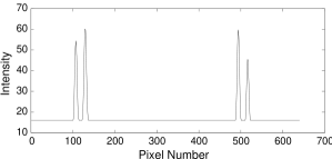
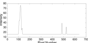
The two first order modes from the analysing hologram, when the input is a Gaussian beam, are LG0,+2 and LG0,-2 modes (fig. 3). However we see that if an LG02 mode is incident on the analyser, one diffracted order from the analyzing hologram ‘fills in’ to give a Gaussian and the other is transformed into a higher order LG mode (fig. 4). The ‘filling in’ is therefore an indicator of the angular momentum in the incident beam. With a Gaussian input, which has no orbital AM, two vortices were produced at the two first order modes. So the pixels on the CCD that correspond to the centre of the vortices were then monitored, as a signal at these centre pixels means that the input beam has orbital AM. The LG02 has a known orbital AM of 2 per photon, and was used to calibrate the signal at the centre pixels.


An elliptical beam scattered by a rod at an angle to the beam’s major axis has angular momentum due to the torque tending to align the rod with the major axis. Monitoring the centre pixels of the first order modes from the analysing hologram, we were able to measure the orbital angular momentum flux of the beam, and hence the torque exerted on the rod. The difference between the signal at the two centre pixels shows a sinusoidal variation as the angle of the bar is rotated with respect to the elliptical beam in agreement with theory (fig. 5). Since the torque is proportional to the beam power, we show the torque efficiency, given here in units of per photon. This is the ratio of the torque to the power divided by the optical angular frequency ().
The torque measured is dependent on the phase thickness of the rod. The phase thicknesses of a number of rods, that were exposed for different periods of time during the contact print process, were measured using a Michelson interferometer. The phase object was imaged onto a rotating screen and recorded using a CCD camera. The phase shift of each rod could then be determined from the shift in fringes of the interference pattern (fig. 6).

The rods corresponding to the interference patterns in fig. 6 were placed in the elliptical beam at 45 degrees to the major axis of the elliptical beam when the spatial torque is greatest. Therefore the torque as a function of phase shift was found (fig, 7).
V Discussion and Conclusion
We have shown that in the macroscopic environment, the orbital angular momentum in a transmitted beam can be measured, allowing the torque on a phase object to be determined. The theoretical results show good agreement with the experimental data.
In this experiment the orbital angular momentum transfer was found to be as much as 0.8 per photon, compared to 0.05 for the alignment due to spin angular momentum for a rod in optical tweezers with a Gaussian beam Bishop et al. (2003). As the orbital component is of considerable size it is of potentially useful technological application if incorporated into optical tweezers. Also, the effectiveness of this technique to measure orbital angular momentum allows for complete measurements of the torque in optical tweezers. So beams that contain an orbital component are not only useful for micromanipulation, but also the torques involved can be fully characterised.
References
- Ashkin et al. (1986) A. Ashkin, J. M. Dziedzic, J. E. Bjorkholm, and S. Chu, Opt. Lett. 11, 288 (1986).
- He et al. (1995a) H. He, M. E. J. Friese, N. R. Heckenberg, and H. Rubinsztein-Dunlop, Physical Review Letters 75, 826 (1995a).
- Friese et al. (1996) M. E. J. Friese, J. Enger, H. Rubinsztein-Dunlop, and N. R. Heckenberg, Physical Review A 54, 1593 (1996).
- Simpson et al. (1997) N. B. Simpson, K. Dholakia, L. Allen, and M. J. Padgett, Opt. Lett. 22, 52 (1997).
- Friese et al. (1998a) M. E. J. Friese, T. A. Nieminen, N. R. Heckenberg, and H. Rubinsztein-Dunlop, Opt. Lett. 23, 1 (1998a).
- Poynting (1909) J. H. Poynting, Proc. R. Soc. Lond. A 82, 560 (1909).
- Beth (1936) R. A. Beth, Physical Review 50, 115 (1936).
- Allen et al. (1992) L. Allen, M. W. Beijersbergen, R. J. C. Spreeuw, and J. P. Woerdman, Physical Review A 45, 8185 (1992).
- Friese et al. (1998b) M. E. J. Friese, T. A. Nieminen, N. R. Heckenberg, and H. Rubinsztein-Dunlop, Nature 394, 348 (1998b), erratum in Nature, 395, 621 (1998).
- Higurashi et al. (1998) E. Higurashi, R. Sawada, and T. Ito, Applied Physics Letters 73, 3034 (1998).
- Bishop et al. (2003) A. I. Bishop, T. A. Nieminen, N. R. Heckenberg, and H. Rubinsztein-Dunlop, Phys. Rev. A 68, 033802 (2003).
- Bayoudh et al. (2003) S. Bayoudh, T. A. Nieminen, N. R. Heckenberg, and H. Rubinsztein-Dunlop, Journal of Modern Optics 50, 1581 (2003).
- Bonin et al. (2002) K. D. Bonin, B. Kourmanov, and T. G. Walker, Opt. Express 10, 984 (2002).
- Santamato et al. (2002) E. Santamato, A. Sasso, B. Piccirillo, and A. Vella, Opt. Express 10, 871 (2002).
- O’Neil and Padgett (2002) A. T. O’Neil and M. J. Padgett, Opt. Lett. 27, 743 (2002).
- Dasgupta et al. (2003) R. Dasgupta, S. K. Mohanty, and P. K. Gupta, Biotechnology Letters 25, 1625 (2003).
- Bingelyte et al. (2003) V. Bingelyte, J. Leach, J. Courtial, and M. J. Padgett, Appl. Phys. Lett. 82, 829 (2003).
- He et al. (1995b) H. He, N. R. Heckenberg, and H. Rubinsztein-Dunlop, J. Mod. Opt. 42, 217 (1995b).
- Mair et al. (2001) A. Mair, A. Vaziri, G. Weihs, and A. Zeilinger, Nature 412, 313 (2001).
- Leach et al. (2002) J. Leach, M. J. Padgett, S. M. Barnett, S. Franke-Arnold, and J. Courtial, Phys. Rev. Lett. 88, 257901 (2002).
- Humblet (1943) J. Humblet, Physica 10, 585 (1943).
- Crichton and Marston (2000) J. H. Crichton and P. L. Marston, Electronic Journal of Differential Equations Conf. 04, 37 (2000).
- Siegman (1986) A. E. Siegman, Lasers (Oxford University Press, Oxford, 1986).
- Nieminen et al. (2003) T. A. Nieminen, H. Rubinsztein-Dunlop, and N. R. Heckenberg, J. Quant. Spectrosc. Radiat. Transfer 79-80, 1005 (2003).
- Beijersbergen et al. (1993) M. W. Beijersbergen, L. Allen, H. E. L. O. van der Veen, and J. P. Woerdman, Optics Communications 96, 123 (1993).
- Courtial et al. (1997) J. Courtial, K. Dholakia, L. Allen, and M. J. Padgett, Optics Communications 144, 210 (1997).
- Schulz et al. (1997) F. M. Schulz, K. Stamnes, and J. J. Stamnes, J. Opt. Soc. Am. A 16, 853 (1999).