Measuring the gain dynamics in a conjugated polymer film
Abstract
We present a simple method for measuring the gain decay time in a conjugated polymer film by optically exciting the film with two mutually delayed ultrashort pump pulses. When the pump is set at such a power level that amplified spontaneous emission marginally develops along the polymer waveguide, the total output emitted from its edge decays exponentially as a function of the interpulse delay. The corresponding decay time represents the decay time of the gain of the polymer material.
Conjugated polymers are believed to carry great promise for application as gain material in organic solid-state lasers. They cover the whole visible spectral range and offer the prospect of being electrically driven. Recently, a first electrically driven organic laser has been realized using a crystalline material [1], but lasing from conjugated polymers has so far only been achieved in an optically pumped device. In the first optically pumped thin-film polymer laser a planar microcavity was employed [2]. Since then various other optically driven polymer lasers have been reported, using a variety of cavity configurations [3, 4, 5].
In a planar microcavity, a polymer layer is sandwiched between two highly reflecting mirrors. The laser light then propagates perpendicular to the active layer, just as in a vertical-cavity surface-emitting semiconductor laser. In this configuration the gain length is limited by the thickness of the layer or the absorption length of the pump light (which usually doesn’t exceed 100 nm). Contrary, this limit doesn’t occur for configurations in which the generated field propagates along the polymer film, acting as a waveguide. In this case the gain length is determined by the dimensions of the excitation beam, which offers the possibility to generate strong amplified spontaneous emission (ASE) along the waveguide, even in the absence of any feedback [6, 7].
To characterize the suitability of a specific conjugated polymer film for laser applications, the gain and loss and their corresponding dynamics need to be measured. The pump-probe technique has proven to be especially powerful here, providing a tool to measure stimulated emission and photoinduced absorption on a sub-picosecond time scale [8, 9, 10, 11]. In this technique, the polymer film is excited with a femtosecond pump pulse and the resulting change in optical transmission () is measured as a function of time by probing the excited region with a very weak, delayed, ultrashort probe pulse. Usually the probe pulse has a very broad spectrum, allowing spectrally resolved measurements of stimulated emission () and photoinduced absorption (). In addition to yielding the actual value of at zero delay for all probe wavelengths, this technique also provides data on the variation of as a function of time. Specifically, one can determine the decay time of the stimulated emission. In order to achieve lasing in a given device, this decay time should at least exceed the time that is needed for the laser field to build up in this device. In solid polymer films usually diminishes on a time scale much shorter than the photoluminescence lifetime of the polymer. Various mechanisms which have been heavily discussed in literature lie at the root of this fast decay [10, 12, 13, 14]. These include photo-oxidation [15], film morphology [16] and pump intensity [11].
In this Letter we put forward a new and simple method for measuring the decay time of the gain in thin solid films of a conjugated polymer. We employ the waveguide configuration and excite the film in a pencil-shaped region using two pump pulses, with a variable interpulse delay. We measure the time-integrated output of the optically excited stripe as a function of interpulse delay. We directly extract the gain decay time from these measurements.
Our sample is made by spin coating a heated and stirred solution of a poly-(-phenylene vinylene) (PPV) copolymer in toluene (5 mg/ml) on top of a glass substrate. The copolymer, referred to as HB1221, consists of four different phenyl-PPVs (25% each); the chemical structure and synthesis route have been published in Ref. [17]. The substrate-film-air stack (with refractive indices , and , respectively) forms an asymmetrical waveguide with a thickness of 100 nm, supporting the propagation of the fundamental TE-mode [7]. After spin coating the substrate is broken in order to access the more homogeneous part of the film in the middle of the substrate and to create a sample with relatively sharp edges. We excite the film with two ultrashort pump pulses ( 130 fs, nm, 1 kHz repetition rate), one being delayed relative to the other. We shape the excitation beam using lenses and a slit to make the intensity distribution homogeneous. Subsequently it is focussed into a stripe of mm on the sample. We measure the light emitted along the stripe. The setup is shown in the inset of Fig. 1.
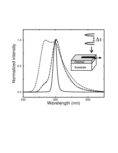
First we provide some characteristics of the polymer waveguide under single-pulse excitation. The spectrum of the emitted light is shown in Fig. 1 for a range of pump energies. At low pulse energy ( nJ) the broad photoluminescence spectrum of the polymer film is observed (dashed curve). When the pulse energy is increased a narrow peak develops at nm (long-dashed curve), which completely comes to dominate the output at even higher pump energies (10 nJ, solid curve). Another characteristic is the input-output curve of the stripe as shown in Fig. 2. It shows the temporally and spectrally integrated output that is emitted from the edge of the polymer film. The signal is measured with a slow photodiode in combination with a gated integrator. Notwithstanding the absence of a feedback structure, the curve shows a clear threshold around 5 nJ. In the vicinity of this point the input-output curve is highly nonlinear. We will employ this nonlinearity to obtain insight into the dynamics of the gain.

The output spectral power on one side of the stripe with length is given by:
| (1) |
Here, represents the net optical gain, as induced by the pump pulse. The linear absorption in the waveguide is denoted by ; is related to the photoluminescence spectral power per unit wavelength. The optical gain is associated with the presence of primary excitons, which may be described as a four-level system. The gain decay time is determined by radiative and nonradiative decay of the exciton population. Eq. (1) has been derived from the laser rate equations, assuming that the gain decays slowly as compared to the single-pass transit time along the stripe ( ps); the latter time will be neglected henceforth. Because we use ultrashort pump pulses, the gain coefficient is at its maximum value at and subsequently diminishes. We assume the gain decays via a single exponential.
In order to measure the decay time of the gain in our waveguide we excite the polymer film at such a power level that there is very little stimulated emission, the output being dominated by spontaneous emission (e.g. at 4 nJ, see Fig 2). After some delay we reexcite the film with a second pump pulse, identical to the first. We measure the time-integrated signal emitted by the stripe upon this dual-pulse excitation as a function of the interpulse delay. For excitation with two pump pulses of equal intensity, having an interpulse delay , the emission is given by Eq.(1), with:
| (2) |
Here represents the double-pulse gain coefficient, while the gain upon single-pulse excitation is represented by . We now define and as the output energies at the edge of the film for single and double pulse excitation, respectively. The output energy is obtained by integrating over both time and wavelength. When the delay is much longer than the decay time of the gain, the time-integrated double-pulse output simply equals twice the single-pulse output (). However, when the delay is short, the double pulse output is larger than because of the nonlinearity of Eq.(1). This is most easily seen at zero delay. The input-output curve immediately shows that the output at 8 nJ pump energy is considerably larger than twice the output at 4 nJ. It is easy to show that, for , the excess output
| (3) |
decays exponentially as a function of the interpulse delay , assuming to decay exponentially. In particular, it can be shown that the decay rate of directly yields the decay rate of the gain coefficient .

In Fig. 3 we show the time-integrated output that is emitted from the edge of our substrate as a function of the interpulse delay at a single-pulse excitation energy of 4 nJ/pulse (J/cm2). As expected, the curve is symmetrical with respect to zero delay. The fitted exponentials (dashed curves), are in excellent agreement with the experimental data, indicating that the excess output indeed decays exponentially, the decay time being ps. The gain coefficient is thus estimated to have a decay time of ps as well. The asymptotic values of the fits correspond to twice the single pulse output, since in the long-delay limit the two output pulses become independent.

In order to check the validity of our approach we have also applied the conventional pump-probe technique to our sample, again using a low excitation density (J/cm2). The probe wavelength has been set at nm (gain maximum), the same wavelength as selected by the gain medium when ASE develops in the waveguide. The results are shown in Fig. 4, representing a single exponential decay of 43 ps, in excellent agreement with the result obtained with the method introduced in this Letter.
Our technique thus provides a reliable tool to measure the decay time of the gain in a thin film of light-emitting polymers. The primary advantage of the technique introduced here is its simplicity. No white-light generation is required and due to the long gain length, the signals are large. This makes the method well suited for studying systems that exhibit very small gain. Moreover the gain decay time is automatically measured at the wavelength at which the net gain is maximum and stimulated emission will build up.
In conclusion, when pumping a polymer waveguide with two excitation pulses at such a power level that the excitation energy of a single pump pulse is just below the threshold value for ASE, the total output upon double pulse excitation strongly depends on the interpulse delay. We have shown that this behavior can be exploited to measure the decay time of the gain in a very simple way: the total output emitted from the edge of the waveguide decays exponentially as a function of the interpulse delay with a characteristic time that represents the decay time of the gain.
This work is part of the research programme of the Stichting voor Fundamenteel Onderzoek der Materie (FOM, financially supported by the Nederlandse Organisatie voor Wetenschappelijk Onderzoek (NWO)) and Philips Research.
References
- [1] J. H. Schön, Ch. Kloc, A. Dodabalapur, and B. Batlogg, Science 289, 599 (2000).
- [2] N. Tessler, G. J. Denton, and R. H. Friend, Nature 382, 695 (1996).
- [3] Y. Kawabe, Ch. Spiegelberg, A. Schültzgen, M. F. Nabor, B. Kippelen, E. A. Mash, P. M. Allemand, M. Kuwata-Gonokami, K. Takeda, and N. Peyghambarian, Appl. Phys. Lett. 72, 141 (1998).
- [4] M. D. McGehee, M. A. Díaz-García, F. Hide, R. Gupta, E. K. Miller, D. Moses, and A. J. Heeger, Appl. Phys. Lett. 72, 1536 (1998).
- [5] S. Riechel, U. Lemmer, J. Feldmann, T. Benstem, W. Kowalsky, U. Scherf, A. Gombert, and V. Wittwer, Appl. Phys. B. 71, 897 (2000).
- [6] M. D. McGehee, R. Gupta, S. Veenstra, E. K. Miller, M. A. Díaz-García, and A. J. Heeger, Phys. Rev. B 58, 7035 (1998).
- [7] C. Zenz, W. Graupner, S. Tasch, and G. Leising, J. Appl. Phys. 84, 5445 (1998).
- [8] W. Graupner, G. Leising, G. Lanzani, M. Nisoli, S. De Silvestri, and U. Scherf, Phys. Rev. Lett. 76, 847 (1996).
- [9] B. J. Schwartz, F. Hide, M. R. Andersson, and A. J. Heeger, Chem. Phys. Lett. 265, 327 (1997).
- [10] S. C. Jeoung, Y. H. Kim, D. Kim, J. Y. Han, M. S. Jang, J. I. Lee, H. K. Shim, C. M. Kim, and C. S. Yoon, Appl. Phys. Lett. 74, 212 (1999).
- [11] G. Wegmann, B. Schweitzer, D. Hertel, H. Giessen, M. Oestreich, U. Scherf, K. Müllen, and R. F. Mahrt, Chem. Phys. Lett. 312, 376 (1999).
- [12] X. Long, A. Malinowski, D. D. C. Bradley, M. Inbasekaran, and E. P. Woo, Chem. Phys. Lett. 272, 6 (1997).
- [13] S. V. Frolov, M. Ozaki, W. Gellermann, M. Shkunov, Z. V. Vardeny, and K. Yoshino, Synth. Met. 84, 473 (1997).
- [14] G. H. Gelinck, J. M. Warman, M. Remmers, and D. Neher, Chem. Phys. Lett. 265, 320 (1997).
- [15] G. J. Denton, N. Tessler, N. T. Harrison, and R. H. Friend, Phys. Rev. Lett. 78, 733 (1997).
- [16] T.-Q. Nguyen, I. B. Martini, J. Liu, and B. J. Schwartz, J. Phys. Chem. B 104, 237 (2000).
- [17] H. Spreitzer, H. Becker, and P. Stössel, Substituted poly(arylene vinylenes), method for the production thereof and their use in electroluminescent devices, Patent nr. WO 01/34722, 2001.