Hydrodynamic theory of de-wetting
Abstract
A prototypical problem in the study of wetting phenomena is that of a solid plunging into or being withdrawn from a liquid bath. In the latter, de-wetting case, a critical speed exists above which a stationary contact line is no longer sustainable and a liquid film is being deposited on the solid. Demonstrating this behavior to be a hydrodynamic instability close to the contact line, we provide the first theoretical explanation of a classical prediction due to Derjaguin and Levi: instability occurs when the outer, static meniscus approaches the shape corresponding to a perfectly wetting fluid.
The forced wetting or de-wetting of a solid is an important feature of many environmental and industrial flows. In typical applications such as painting, coating, or oil recovery it is crucial to know whether the solid will be covered by a macroscopic film or not. If a fiber is plunging into a liquid bath to be coated (wetting case), the speed can be quite high (m/sec) SK03 , while maintaining a stationary contact line. In the opposite case of withdrawal (de-wetting), a stationary contact line is observed only for very low speeds, and a macroscopic film is deposited SP91 ; Q99 typically at a speed of only a few cm/sec. Yet no theoretical explanation for this instability exists, or of the fundamental difference between the two cases.
It is well known HS71 ; DD74 that viscous forces become very large near a moving contact line, and are controlled only by some microscopic cut-off , for example a slip length HS71 ; H83 . As a result of the interplay between viscous and surface tension forces, the interface is highly curved, and the contact line speed is properly measured by the capillary number , where is the viscosity of the fluid and the surface tension between fluid and gas. Owing to this bending the interface angle measured at, say, away from the contact line differs G85 ; K93 ; FJ91 ; MGD93 significantly from the microscopic angle directly at the contact line.
It was first proposed by Derjaguin and Levi DL64 , and later reiterated by others BR79 , that instability occurs if this dynamic interface angle reaches zero. Apart from the fact that there is no justification for this condition, it does not lead to a unique criterion since the angle depends on the position where it is evaluated. However, it was noted experimentally SP91 that the interface profile at the critical speed corresponds to a static meniscus with zero equilibrium contact angle, except in the immediate neighborhood of the contact line. Another important set of experimental observations Q91 was performed with fluids of different viscosities and equilibrium contact angles in a capillary tube: it was found that instability occurred if exceeds a critical value, strongly pointing to a hydrodynamic mechanism for the instability.
To explain the physical mechanism behind the instability, we note that the interface shape near the contact line must have the form
| (1) |
since the cut-off is the only available length scale. The dependence on was put in for later convenience. As expected, the curvature becomes very large at the contact line, since is in the order of nanometers. As the curvature of the local solution has to match to a value of order unity in the static outer part of the profile, the usual boundary condition for is one of vanishing curvature for large . In the wetting case this leads to an asymptotic solution first found by Voinov V76 and an expression for the interface angle usually referred to as “Tanner’s law” G85 .
However, it is a well-known but little appreciated fact DW97 that Voinov’s solution fails away from the contact line in the de-wetting situation. Instead, the local solution always retains a positive curvature, and will fail to match to an outer solution in the limit of small . At the critical speed, the necessary compromise between the inner solution near the contact line and the outer static solution has been pushed to the limit: from all possible inner solutions, the one with the smallest possible curvature is selected. The outer solution, on the other hand, realizes the solution with the largest curvature, which happens to be the one corresponding to zero contact angle, in agreement with the criterion of Derjaguin and Levi. Note that this mechanism differs from the one proposed by de Gennes G86 , which is based entirely on properties of the local solution near the contact line. In a companion paper E03 we show that de Gennes’ local solution is inconsistent with a class of contact line models, such as the slip model considered here.
To lay down the theory behind the above argument, we choose a plate being withdrawn from a liquid bath (see Fig.1) as a test case, a geometry which was studied in detail in H01 . There it was found numerically that there exists a critical capillary number , above which no static solution exists, in agreement with the experimental findings described above. If both and the equilibrium contact angle are small, one can treat the problem in the framework of lubrication theory, assuming a parabolic flow profile. This greatly simplifies the problem, but without altering its essential structure.

To relieve the corner singularity at the moving contact line, we allow the fluid to slide across the solid surface, following the Navier slip law H83
| (2) |
at the plate, where is the thickness of the fluid layer. The resulting lubrication equation is H01
| (3) |
where we consistently used the small-angle approximation . All lengths are scaled by the capillary length .
The left hand side of (3) corresponds to viscous forces, diverging as the contact line position is approached, but weakened by the presence of slip. Close to the contact line, viscous forces are balanced by surface tension forces (first term on the right), resulting in a highly curved interface near the contact line. The other two terms stem from gravity and only come into play at greater distances. We also assume that the angle at the contact line is constant, which then has to be the equilibrium contact angle, in order to give the right result at vanishing speed. Note that we have used the simplest possible contact line model, and no special significance should be attached to our choice. Since the instability mechanism is hydrodynamic, any local contact line model can be incorporated into our description. Far away from the interface the surface coincides with the liquid bath, so the third boundary condition is .
To disentangle the local contact line behavior from the far-field meniscus, we transform equation (3) into similarity variables (1):
| (4) |
with boundary conditions , and . The three parameters remaining in the problem are the rescaled capillary number , the rescaled cut-off , and the relative inclination angle .
Since we are interested in the limit of being very small, we will first look at the equation for , as appropriate close to the contact line. As mentioned above, in the limit of large this equation behaves very differently, depending on whether or . This can be understood from the simplified equation , which can be integrated completely BO78 ; DW97 . Namely, if (wetting), there exists an asymptotic solution for V76 , whose curvature vanishes at infinity.
If on the other hand (de-wetting), all solutions have a finite curvature at infinity. Solutions which obey our boundary condition can be written DW97 parametrically as
| (7) |
where and are Airy functions. The limit corresponds to . For large , the curvature becomes DW97
| (8) |
where solves the equation
| (9) |
Since the solution extends to , has to be the largest root of (9).
The constant can be determined by matching (7) to the cutoff region near the contact line, where one finds in the limit of small DW97 . Comparing this to the first order expansion of the full equation (4) near the contact line H83 ; E03 ,
| (10) |
we find . The matching described here was investigated in greater detail for the case in E03 . We found that higher order corrections in were surprisingly weak, and depended only very little on the type of cut-off used at the contact line. Thus we are confident that the same holds true in the present case.
At the critical capillary number the only remaining parameter, which is , can be determined from the condition that should be minimal, in other words must be maximal among solutions of (9). By choosing we can in fact ensure that assumes its global maximum , which occurs for . In summary, we find then for the critical solution that minimizes the curvature
| (11) |
which is now given exclusively in terms of the rescaled capillary number .
The solution (7) has to be matched to an outer solution of (3), valid away from the contact line. In the spirit of the classical technique H83 employed for the spreading drops, this is a static solution of (3), but with an apparent contact angle different from . The general solution of (4) with gives
| (12) |
so the curvature at the plate is . The largest curvature for which (12) still makes sense is , at which point the apparent contact angle has reached zero.
The two solutions have to be matched together, such that the curvature of (7) for large arguments agrees with that of (12) for small arguments. At large capillary number this will no longer be possible, since becomes larger than . At the critical capillary number , (11) thus has to be equated with , giving
| (13) |
for the critical rescaled capillary number . This equation completely determines the stability boundary found numerically in H01 , as function of all parameters. It also implies that for a given geometry, instability occurs if the parameter exceeds a critical value (up to very small logarithmic corrections), in agreement with experiment Q91 .
For our procedure to be consistent, though, we need to make sure that the two solutions (7) and (12) have sufficient overlap to be matched. The inner and outer solutions at are, in summary,
where is a universal function given by (7) with . Thus if the large- limit of overlaps with the small- limit of , which translates into .
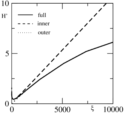
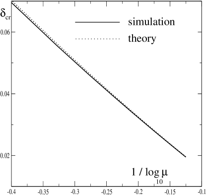
In Fig. 2 we show the result of a numerical integration of (4) for at the critical capillary number. The interface slope follows the static solution perfectly almost up to the contact line, where it has to turn over, while the static solution extrapolates to zero. Coming from the interior, (7) describes the solution equally well up to the turning point. Note that there are no adjustable parameters in Fig. 2, we simply took the inner and outer solutions in the critical case. In fact, even for , when there is not yet much overlap between the two solutions, equation (13) already works extremely well in describing the loss of the stationary solution, as shown in Fig. 3. Again, no parameter was adjusted to achieve this comparison.
Beyond the wet-dry transition studied here, in H01 two more states have been described, characterized by thin and thick wetting films, respectively. The stability of these solutions, and possible hysteresis phenomena remain to be investigated. It is important to note that our approach is not limited to the moving plate geometry studied here, nor is it restricted to a specific contact line model, since it is based entirely on hydrodynamic arguments away from the contact line. For example, if van-der-Waals forces are dominant near the contact line GHL90 , the parameter in (13) simply needs to be replaced by , where is the Hamaker constant.
To generalize to a different geometry, one has to replace (12) by the appropriate static solution for the problem at hand. This is done almost trivially for the case of a vertical wall LL84 , and easily extended H01 to the flow in a narrow capillary, to be able to compare directly to experiments Q91 . Hocking H01 found that the present slip theory correctly predicts to be a constant, but overestimates this constant by a factor of two, if reasonable values for the slip length are assumed. Reasons for this discrepancy could be both the considerable contact angle hysteresis in the experiment Q91 , and failure of the simple contact line model used in our calculation. A new set of experiments, using the plate geometry, is being planned to clear up these questions Q03 .
Another important generalization is to higher dimensional problems, in which the contact line does not remain straight. An instability toward inclined contact lines was observed in BR79 , as well as in recent experiments with drops running down an inclined plane PFL01 . To explain the characteristic inclination angle of such a contact line, one needs to identify a characteristic speed of de-wetting BR79 ; SLW02 , which our present approach effectively provides.
Acknowledgements.
Special thanks are due to Petr Braun for numerous insightful discussions.References
- (1) P. G. Simpkins and V. J. Kuck, J. Col. Interf. Sci. 263, 562-571 (2003).
- (2) R.V. Sedev and J.G. Petrov, Colloids and Surfaces, 53, 147-156 (1991).
- (3) D. Quéré, Annu Rev. Fluid Mech. 31, 347-384 (1999).
- (4) C. Huh and L.E. Scriven, J. Coll. Int. Sci. 35, 85-101 (1971).
- (5) E.B. Dussan V. and S.H. Davis, J. Fluid Mech. 65, 71-95 (1974).
- (6) L.M. Hocking, Q. J. Appl. Math. 36, 55-69 (1983).
- (7) P.G. de Gennes, Rev. Mod. Phys. 57, 827-863 (1985).
- (8) S. Kistler, S. Hydrodynamics of wetting. In Wettability, J. C. Berg (Ed.), Marcel Dekker, New York (1993).
- (9) M. Fermigier and P. Jenffer, J. Coll. Int. Sci. 146, 226-241 (1991).
- (10) J.A. Marsh, S. Garoff, and E.B. Dussan V., Phys. Rev. Lett. 70, 2778-2781 (1993).
- (11) B.V. Derjaguin and S.M. Levi, Film coating theory, Focal Press, London (1964).
- (12) T. D. Blake and K.J. Ruschak, Nature 282, 489-491 (1979).
- (13) D. Quéré, C. R. Acad. Sci. Paris, Série II 313, 313-318 (1991).
- (14) O. V. Voinov, “Hydrodynamics of wetting,” [English translation] Fluid Dynamics 11, 714-721 (1976).
- (15) B.R. Duffy and S.K. Wilson, Appl. Math. Lett. 10, 63-68 (1997).
- (16) P.G. de Gennes, Coll. Pol. Sci. 264, 463-465 (1986).
- (17) J. Eggers, “Towards a description of contact line motion at higher capillary numbers”, submitted to Phys. Fluids (2003).
- (18) L.M. Hocking, Euro. J. Appl. Math. 12, 195-208 (2001).
- (19) C.M. Bender and S.A. Orszag, Advanced mathematical methods for scientists and engineers, Mc Graw-Hill, New York (1978).
- (20) P. G. de Gennes, X. Hua, and P. Levinson, J. Fluid Mech. 212, 55-63 (1990).
- (21) L.D. Landau and E.M. Lifshitz, Fluid Mechanics, Pergamon, Oxford (1984).
- (22) D. Quéré, private communication (2003).
- (23) T. Podgorski, T., J.M. Flesselles, and L. Limat, Phys. Rev. Lett. 87, 036102(1)-(4) (2001).
- (24) H.A. Stone, L. Limat, S.K. Wilson, J.M. Flesselles, and T. Podgorski, C. R. Physique 3, 103-110 (2002).