Simple external cavity diode laser
Abstract
A semiconductor diode laser having a modified Littrow external resonator is described. An additional output coupling mirror in a V-shape configuration of the resonator makes the system more efficient and convenient to operate.
pacs:
42.60.P; 42.55.P; 42.62.FI Introduction
Well-known achievements in atomic physics of the last two decades became possible due to the progress in the semiconductor diode lasers. External cavity diode lasers (ECDL) are the most important in this context. They are able to produce powerful coherent radiation in the vicinity of many important atomic resonances. Details of various diode laser designs and laser performance are described in a number of papers, see, e.g., Refs. Wieman91RSI ; MacAdam92AJP ; Maki93OC ; Corwin98AO ; Yashchuk00RSI .
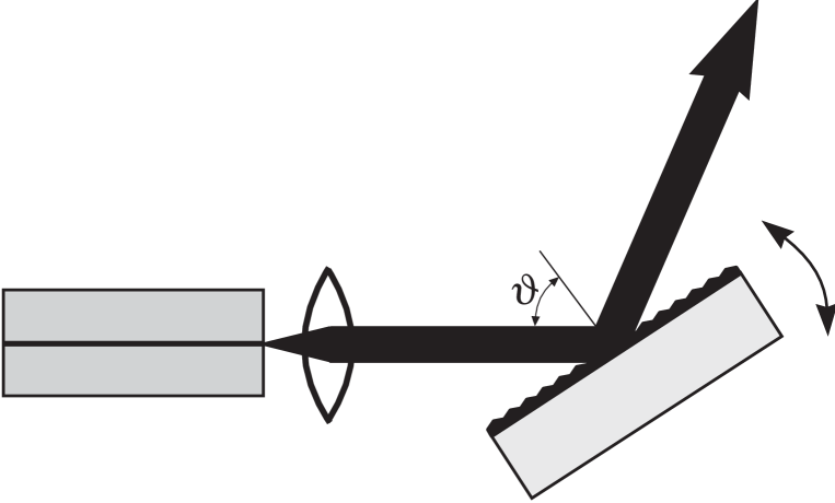
Most popular arrangement of an external cavity of a diode laser is based on the grating feedback in the Littrow configuration, Fig. 1. In such resonator, the grating reflects back to the diode the radiation in non-zero diffraction order. The laser output coupling is performed through zero diffraction order of the grating. Although such resonator configuration looks the simplest possible there are some inconveniences in its practical realization. In the present paper we describe a modified diode laser resonator that is more efficient and convenient. This approach to the laser wavelength selection by grating is based on our previous experience with dye lasers Ishchenko80 . Another source of helpful ideas for this work was an excellent monograph Malyshev79 devoted to the classical spectral instruments.
II Littrow resonator
Performance of the laser having Littrow resonator (Fig. 1) is determined by the three major factors: grating angular dispersion, grating reflection coefficient and output coupling coefficient. The grating formula for the Littrow configuration,
| (1) |
allows to deduce the angular dispersion, , of the grating,
| (2) |
Here, is the distance between two neighbouring groves of the grating, is the diffraction order. From this expression one can conclude that the angular dispersion, , is growing if is decreasing. It motivates ones to use in most designs of the laser external cavities the gratings having large density of groves.
One can modify the expression (2) for by substituting the diffraction order from the grating formula (1) and obtain,
| (3) |
This equation shows that the angular dispersion of the grating and consequently the frequency resolution do not depend on the density of groves if one works at predefined diffraction angle . This conclusion allows to make an important simplification of the design by using cheaper and better quality gratings having low density of groves.
Another conclusion from Eq. (3) is that the angular dispersion is larger at larger diffraction angles . The drawback of working at large is that for an ordinary flat grating the reflection coefficient decreases at large . One knows (see, e.g., Malyshev79 ) that the reflection at large diffraction angles can be increased by using the gratings having the groves of triangular shape that increases the grating blazing angle. Consequently, the gratings having low density of groves have an additional advantage because for such gratings a modern technology gives better quality of groves.
III V-shape resonator
Another important parameter determined laser performance is the magnitude of the resonator output coupling. Optimal output coupling is a complicated function of the laser medium gain, resonator losses and power saturation mechanism. In practice, one uses to try a few output couplers to find out the right one for better laser performance. For the Littrow resonator in Fig. 1 the output coupling is determined by the properties of particular grating and cannot be changed by will.
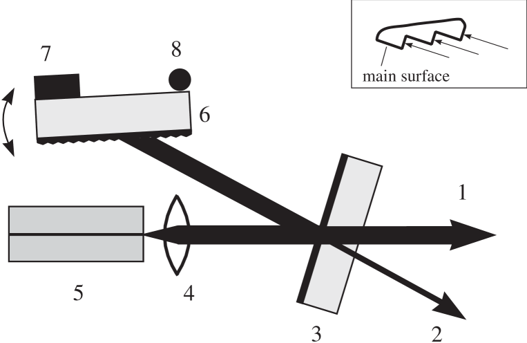
One way to solve this problem is to use an extra reflector inside a Littrow resonator Wieman91RSI . We propose here to use an output coupling mirror in a V-shape resonator, Fig. 2.
The grating used in this work had 600 groves/mm and the blazing angle equal specified by the manufacturer. This blazing angle is determined by the orientation of the main surface of the grove (see insert in Fig. 2). This surface of the grove would allow us to work at the diffraction angles . Technology of the grating production is such that the groves have a triangular shape and one can use another surface of the grove to work at much larger blazing angle Malyshev79 . In our case it allows us to work at the blazing angle, , that corresponds to the 4-th diffraction order for . Reflection coefficient of our grating in the 4-th order was . The reflection coefficient in the 0-th order at appeared to be very low, . In fact, this circumstance has motivated us to modify the usual Littrow resonator.
We have used standard Mitsubishi laser diode, ML6XX24 series, without a special antireflection coating on the crystal facet. Concequently, the laser resonator consists of the two, one is formed by the diode crystal itself and another is formed by the external resonator. Fine tuning of the laser frequency needs in this case simultaneous tuning of these two resonators to avoid nonlinearities due to the frequency pulling effect. It was performed in our laser by synchronous linear modulation of the diode current and the grating tilting by piezo transducer. The length of the external resonator was equal to 3.5 cm.
Stable laser characteristics demands rather precise temperature stabilization of the laser diode. It was done in the setup with the help of Peltier element and feedback electronics. The temperature stability was better than 1 mK. The external laser resonator was not temperature stabilized actively. Instead, it was placed on aluminium plate that had good thermal contact with the massive metal optical table.
IV Laser performance
The specified wavelength of the laser diode was 785 nm at 25 C. In the experiments with the rubidium vapour the laser diode was kept at 14 C and its own frequency at such temperature was nm. Power of the laser diode itself (without an external resonator) was 35 mW at the electrical current through the diode equal 72 mA and the temperature equal 14 C.
The laser produces two beams (Fig. 2). Direction of the main beam does not depend on the grating and mirror orientation. Direction of the second beam changes if the laser wavelength is tuned like it does in the Littrow resonator. Power of the external cavity diode laser having the flat output coupling mirror was 18 mW, combined from 14 mW of the main output beam and 4 mW of the second beam. The output coupling mirror having gives 21 mW in the main beam and 3 mW in the second beam. Thus, as one would expect, an adjustment of the output coupling mirror is significant for the laser performance. For the V-shape resonator such adjustment appears to be rather simple procedure.
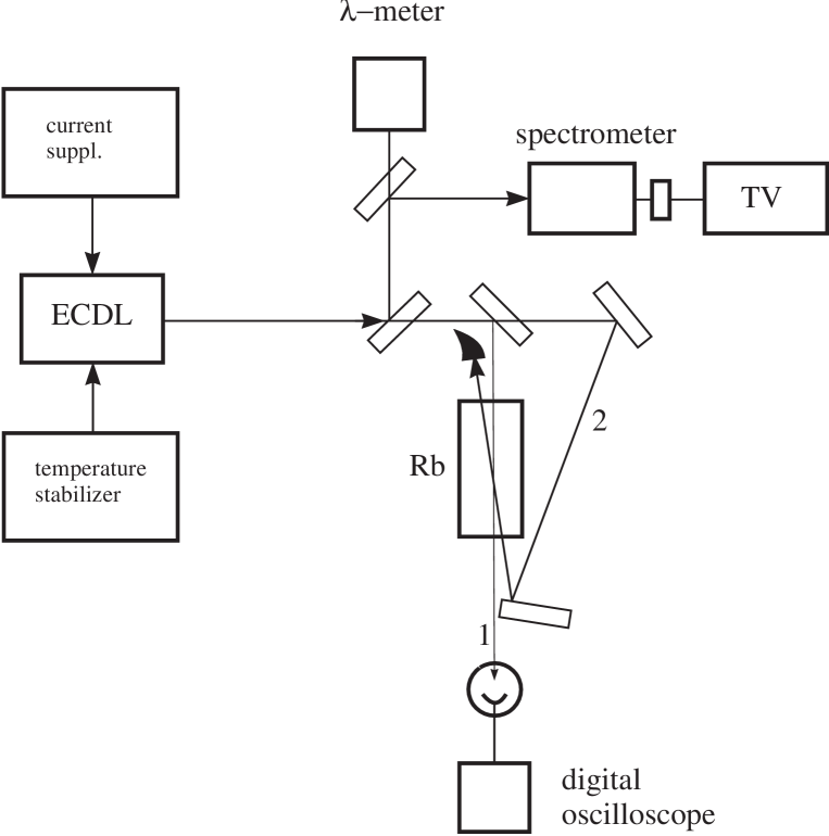
The laser frequency characteristics were measured using the setup shown in Fig. 3. The wavelength of the laser radiation was controlled by the spectrograph having the dispersion equal 0.36 nm/cm on the TV screen and precise –meter having sensitivity equal 50 MHz. Rough frequency tuning of the laser radiation was performed by rotating the mirror that was placed on the tuning head. For the output coupling mirror having the laser wavelength was tuned between 775-785 nm at a constant diode temperature equal 14 C. The range of the laser frequency tuning decreases if one uses output coupling mirror having larger transmission.
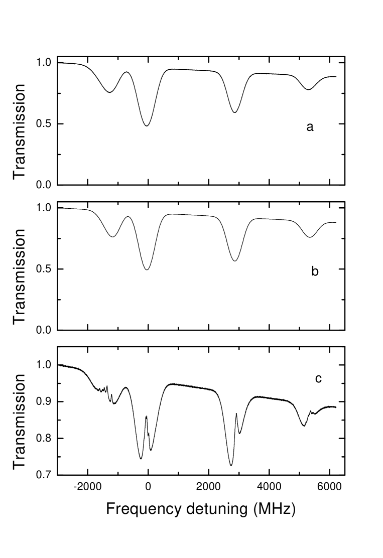
Fine frequency of the laser radiation was performed by simultaneous tilting the grating and linear modulation of the diode electrical current. Frequency tuning was tested by measuring the linear transmission spectra of Rb vapour. For this purpose a weak laser beam passed through a 7.5 cm cell containing Rb vapour at room temperature. The cell contained natural mixture of Rb isotopes and no buffer gas. (The strong counter propagating beam (Fig. 3) was closed in this measurements.) The data are presented in Fig. 4a. This spectrum is the average of 16 frequency scans taken during s. This result shows that the range of the laser frequency fine tuning is larger than 9 GHz. Small decrease of the laser power visible in the Fig. 4a is due to the diode current modulation mentioned above.
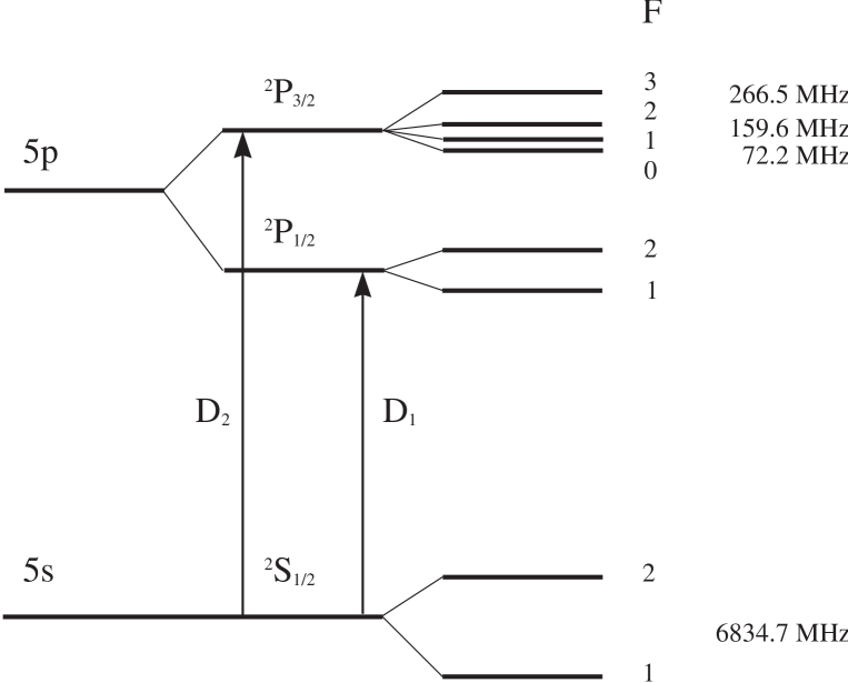
One can compare the measured transmission spectra with the calculated spectrum. The calculation was done using the hyperfine parameters of the 87Rb and 85Rb isotopes from Barwood91APB and the decay rate of the state equal 6 MHz Schmieder70PRA . As an example, the level structure of 87Rb is shown in Fig. 5. The calculated transmission spectra is shown in Fig. 4b. The measured transmission is reproduced by the calculations within 5% if one uses the Rb vapour pressure from Handbook93 . The vapour pressure from Nesmeyanov63 needs 20% increase.
Passive stability of the laser frequency was measured by the two methods. In the first, the transmitted radiation intensity in the vicinity of Rb absorption lines was observed. The laser frequency drift appeared to be 12 MHz/min during in approximately 20 min. Another measurement was done with the help of the -meter. It gives similar value for the frequency drift, 15 MHz/min, for the 20 min observation period.
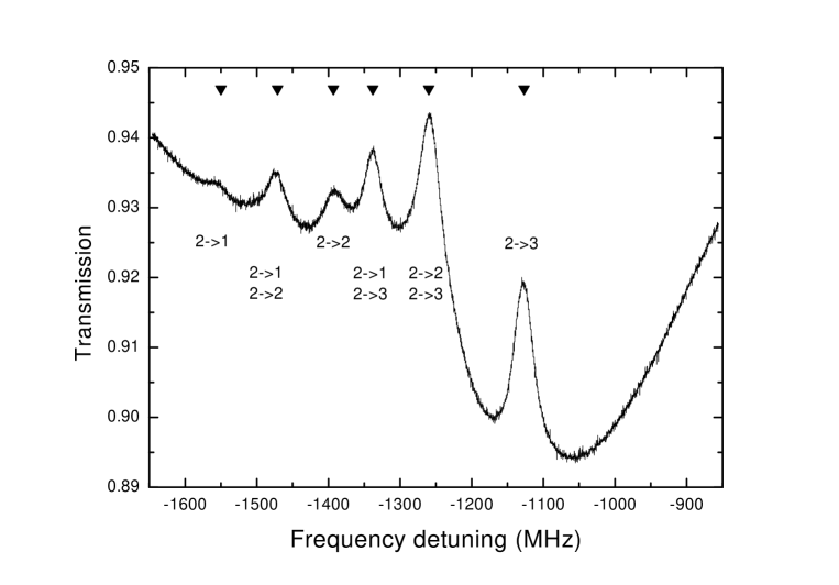
An important parameter of the laser is the radiation linewidth. It can be measured studying the beats of two independent lasers. We have estimated the radiation linewidth using the saturated absorption resonances in Rb vapour. For this, the transmission of weak laser beam was measured in the presence of strong counterpropagating laser beam. The spectra are presented in Fig. 4c and in a larger scale in Fig. 6. These spectra are an average of 16 tracks taken during 1 s. The width (HWHM) of the nonlinear resonance appears to be equal MHz. This width is composed Rautian79 from the fluorescence linewidth (3 MHz for our transition Schmieder70PRA ), the width of the Bennett peak in the velocity distribution in the upper state, estimated as 11 MHz for the strong beam intensity used in the experiment and the laser frequency linewidth. From these data one can estimate that the laser radiation linewidth is on the order of 1 MHz.
V Conclusions
The diode laser having V-shape external cavity is described. The external cavity is a Littrow resonator modified by an additional output coupling mirror. This mirror allows easily adjust the level of the laser output coupling and thus optimize the laser performance, obtaining necessary frequency tuning range, or necessary output power. In the described laser the radiation power constitutes 50% of the laser power without an external resonator. The fine frequency tuning range of the laser is 9 GHz and the radiation linewidth is estimated as being on the order of 1 MHz.
Proposed V-shape external resonator has some advantages in comparison with the traditional Littrow resonator. It is easier now to optimize the diffraction grating that has to have just maximal possible reflection coefficient. Another advantage is that the direction of the main output beam is unaffected by the laser frequency tuning.
Acknowledgments
The work was supported by the Russian Foundation for Basic Research (grant RFBR 03-02-17553) and by the Siberian Branch of the Russian Academy of Sciences through the project ”Laser cooling of gases in magneto-optical traps”.
References
- (1) C. E. Wieman and L. Hollberg, Rev. Sci. Instrum. 62, 1 (1991).
- (2) K. B. MacAdam, A. Steibach, and C. Wieman, Am. J. Phys. 60, 1098 (1992).
- (3) J. J. Maki, N. S. Campbell, C. M. Grande, R. P. Knorpp, and D. H. McIntyre, Optics Comm. 102, 251 (1993).
- (4) K. L. Corwin, Z. Lu, C. F. Hand, R. J. Epstein, and C. E. Wieman, Applied Optics 37, 3295 (1998).
- (5) V. V. Yashchuk, D. Budker, and J. R. Davis, Rev. Sci. Instrum. 71, 341 (2000).
- (6) V. N. Ishchenko, S. A. Kochubei, V. N. Lisitsyn, and P. L. Chapovsky, in Frequency tunable lasers, Thermophysics Institute of the Russian Academy of Sciences, edited by Dr. Sci. V. P. Chebotaev (Thermophysics Institute, 630090 Novosibirsk, Russia, 1980), pp. 21–47.
- (7) V. I. Malyshev, Introduction to experimental spectroscopy (Nauka, Moscow, 1979).
- (8) G. P. Barwood, P. Gill, and W. R. C. Rowley, Appl. Phys. B 53, 142 (1991).
- (9) R. W. Schmieder, A. Lurio, W. Happer, and A. Khadjavi, Phys. Rev. A 2, 1216 (1970).
- (10) CRC Handbook of Chemistry and Physics, 73d edition, 1992-1993.
- (11) A. N. Nesmeyanov, Vapor Pressure Curve of the Chemical Elements (Elsevier, New York, 1963).
- (12) S. G. Rautian, G. I. Smirnov, and A. M. Shalagin, Nonlinear resonances in atom and molecular spectra (Nauka, Siberian Branch, Novosibirsk, Russia, 1979).