The CDF Calorimeter Upgrade for Run IIb
Abstract
The physics program at the Fermilab Tevatron Collider will continue to explore the high energy frontier of particle physics until the commissioning of the LHC at CERN. The luminosity increase provided by the Main Injector will require upgrades beyond those implemented for the first stage (Run IIa) of the Tevatron’s Run II physics program. The upgrade of the CDF calorimetry includes: 1) the replacement of the slow gas detectors on the front face of the Central Calorimeter with a faster scintillator version which has a better segmentation, and 2) the addition of timing information to both the Central and EndPlug Electromagnetic Calorimeters to filter out cosmic ray and beam related backgrounds.
1 THE CENTRAL PRESHOWER AND CRACK DETECTORS
The CDF Central Preshower (CPR) and Central Crack (CCR) detectors will be replaced at the time the silicon detector is replaced for Run IIb.
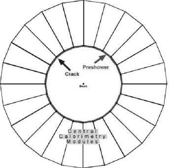
In 1992 the CDF Collaboration installed gas detectors on the front face of the central calorimeter in order to sample early showers and cover the -cracks between calorimeter wedges, as shown in Fig. 1. The CPR has been extensively used in electron identification (ID), providing about a factor 2-3 more rejection of charged pions that pass all other cuts. This extra rejection has been crucial in soft electron ID for b-jet tagging, as was shown in the first top evidence paper [1]. The CPR has been used in several publications involving photon ID. By using conversion rates, which are energy independent, it extended the QCD measurement of direct photons by more than 100 GeV in photon transverse momentum [2].
The CCR, located after a 10 radiation length thick tungsten bar, has been checked for large pulse heights in all the rare events CDF has observed in Run I. The -cracks cover about 8% of the central detector, and in events with multiple electromagnetic objects, the possibility of one object hitting the crack is quite high.
The present slow CPR and CCR gas
detectors will suffer the luminosity increase foreseen for Run IIb. In order to maintain the same Run I capabilities, they will be replaced by scintillator counters read out by Wave-Length Shifting (WLS) fibers. The new CPR will also have a better segmentation and will be used to improve the jet energy resolution by both correcting for energy loss in the dead material in front of it and adding its information in jet algorithms incorporating charged tracking.
1.1 The Detector Design fron Run IIb
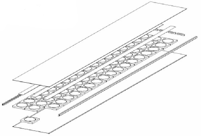
The new CPR will be based on 2cm thick scintillator tiles segmented in and and read out by a 1mm diameter WLS fiber running into a groove on the surface of each tile. Six tiles (12.5x12.5 cm2 each) will cover the front face of each calorimeter tower, and the tiles will be assembled in 48 modules like the one shown in Fig. 2 covering the 48 central calorimeter wedges. After leaving the tiles, the WLS fibers will be spliced to clear fibers which will terminate into plastic connectors at the higher edge of each module. There 5m long optical cables will transmit the light to 16-channel PhotoMultiplier Tubes (PMTs) at the back of the wedge. A current prototype, consisting in scintillator tiles provided by the CDF JINR Dubna group and Pol.Hi.Tech fibers, provided a light yield of 20 (12) photoelectrons at the exit of the tile (after all the optical chain), exceeding the design requirement.
The new CCR will use the same technique but the available space will limit the scintillator thickness to 5mm. Ten tiles, 5cm wide, will cover each -crack with the same calorimeter segmentation of 10 towers/wedge.
2 THE EM TIMING PROJECT
The CDF Collaboration is adding timing information into the readout of the Central and Plug electromagnetic calorimeters (CEM and PEM) using a technique similar to the hadron TDC system. This upgrade would significantly improve the potential of the CDF detector to do high- searches for new physics in data samples with photons in the final state by: 1) reducing the the cosmic ray and beam halo sources of background; 2) checking that all photons in unsual events are from the primary interaction. With sufficient calibration data, there is even the possibility of searching for very long-lived particles which decay (1-10ns) into photons.
2.1 The Hardware Project
The signal from the PMT goes to a Transition Board on the back of a calorimeter readout VME crate. All the lines are passed through the VME backplane into an Amplifier Shaper Discriminator (ASD) which effectively turns the signal into an LVDS digital pulse suitable for use by a TDC.
While the 960 PEM PMTs already have a dynode output designed into the base, a custom splitter is used for the output of the 960 CEM PMTs. The splitter is a fully passive element, completely connectorized, which works by inductively coupling the primary line (for the energy measurement) to the secondary output. The primary output loses a negligible amount of the charge and the secondary line only takes 15% of the output voltage for use to fire the ASD/TDC system.
Several tests of the splitter, both on the test bench and on the detector itself, show no difference between the input shape and height before and after inserting the splitter into the system. For energies 4 (2) GeV for the CEM (PEM), the splitter fires the ASD/TDC system with 100% efficiency. The intrinsic timing resolution, measured using the CEM LED and a splitter into a TDC channel of the hadron calorimeter, is 1.1ns, dominated by the 1ns TDC resolution.
References
- [1] F. Abe et al., Phys. Rev. Lett. 73 (1994) 225.
- [2] F. Abe et al., Phys. Rev. D 48 (1993) 2998; Phys. Rev. Lett. 73 (1994) 2662.