Propagation of a mutually incoherent optical vortex pair in anisotropic nonlinear media
Abstract
We study propagation of a pair of oppositely charged and mutually incoherent vortices in anisotropic nonlinear optical media. Mutual interactions retard the delocalization of the vortex core observed for isolated vortices.
pacs:
42.65.-k,42.65.Sf,42.65.Tg1 Introduction
Isotropic media with a repulsive nonlinearity support localized vortex solitons characterized by a dislocation of the wavefront at the point where the field amplitude vanishes [1]. Vortex solitons have been observed in several types of defocusing nonlinear media, including superfluids, superconductors, optical Kerr media and Bose Einstein condensates. Stability of the solitons depends on the structure of the nonlinearity and the dimensionality of the medium. Planar one-transverse dimensional [(1+1)D] solutions are modulationally unstable in bulk, two-transverse dimensional [(2+1)D] media [2, 3, 4]. Kerr type optical media with a cubic, isotropic, and local nonlinearity support stable (2+1)D vortex solitons [1, 5]. These vortex solitons have attracted considerable attention theoretically[6] and have recently been studied in detail in atomic condensates[7]. A Kerr type nonlinearity is, however, a simplified idealized model of a nonlinear response. The bulk photorefractive nonlinear medium used in the experiments reported here exhibits a nonlinearity that is both anisotropic and nonlocal. This leads to qualitative differences in the spatial dynamics of vortex beams.
One of the most basic phenomena is the propagation of an isolated vortex of unit topological charge. Such a vortex can form a stable soliton in isotropic defocusing media[5]. Theory and experiments have shown that unit charged vortices become delocalized when they propagate in photorefractive media[8, 9, 10]. The nonlinearity in a photorefractive crystal with an externally applied electric field, or photogalvanic response, is anisotropic and nonlocal[11]. The nonlinearity induced by a localized, circular beam is roughly 3 times stronger along the direction of the applied field than in the perpendicular direction (we will refer to the direction of strongest nonlinearity as the axis). Due to the anisotropy a vortex with an initially azimuthally symmetric core profile focuses perpendicular to and stretches along , so that the major axis of the core coincides with the direction of greatest material nonlinearity. Simultaneously the elongated vortex starts to rotate due to its phase structure. The direction of rotation is uniquely determined by the vortex charge; changing its sign changes the sign of the rotation. Eventually the rotation is stopped by the anisotropy so that the major axis of the vortex is aligned at some angle with respect to The stretching, however, proceeds unchecked so that the vortex becomes more and more delocalized. Both theory and experiment show that delocalization of the vortex core is generic in anisotropic media, and not dependent on a specific choice of parameters. The implication is that localized optical vortex solutions and, in particular, vortex solitons of unit topological charge do not exist in these media.
An additional hallmark of anisotropy is the nonlinear decay of a charge vortex into unit charge vortices. The decay, although expected on energetic grounds, does not occur in isotropic media where a high charge vortex is metastable[12], but was observed using a photorefractive crystal as the nonlinear medium[13]. Upon breakup of the input high-charge vortex the resulting charge-one vortices repel each other and form an array aligned perpendicular to . The decay is driven by the intrinsic anisotropy of the medium and takes place for any core profile of the input vortex field. The theory developed in Ref. [13] suggests that the decay of high-charge vortices is possible in local isotropic media provided some anisotropy is introduced in the problem via, e.g., initial boundary conditions.
Given the instability of unit and high charge vortices in anisotropic media it is natural to ask if there exist self-bound field configurations that remain localized under propagation in anisotropic media. Previous experiments[8] have demonstrated that the effects of anisotropy are considerably weakened for a counterrotating pair of vortices with zero net topological charge. When such a pair is aligned perpendicular to it forms a bound state that translates parallel to in a manner that is similar to the translational motion of a counterrotating point vortex pair in fluid dynamics[14]. The translational motion may, however, be inconvenient in the context of optical processing applications. Furthermore, the initial orientation of the pair is crucial for its subsequent evolution. A pair aligned along annihilates due to diffraction.
In this paper we propose, and demonstrate experimentally a novel technique of creating bound vortex structures in anisotropic media that are free of the above mentioned limitations. The main idea is based on the fact that in the prevailing majority of nonlinear media the material response is slow as compared to the frequency of the optical field, and therefore is a function of the time-averaged intensity of this field. If the light field consists of several features separated by frequencies that are fast on the time scale of the material response, the material response will be a function of the sum of these features intensities, whereas the cross-terms oscillating at high frequencies can be neglected. This fact has been known in photorefractive nonlinear optics and used successfully for implementing several optical processing devices [15], as well as (1+1)D solitary structures [16].
We propose to create a bound vortex pair consisting of two copropagating counterrotating vortices sitting on top of each other that are mutually incoherent at the time scales of the nonlinearity. This incoherence can be achieved either by separating the carrier frequencies of the vortices by an amount that is larger than the inverse relaxation time of the medium, or profiling time histories of the input vortex fields such that their time overlap integrated over the relaxation time of the medium is zero. The mutual incoherence of the vortex fields removes the translational motion due to the linear coherence of the vortex pair. At the same time each of the vortices individually tries to rotate in opposite directions which effectively controls the anisotropy induced stretching of a single vortex.
2 Theory
In the theoretical analysis we use the set of equations describing propagation of an electromagnetic field in a photorefractive self-focusing or self-defocusing medium as developed in [11, 17]. In our case the field consists of two temporal features. For definiteness assume that these features are separated by a frequency shift such that , where is the characteristic response time of the nonlinearity:
| (1) |
In the steady state the equations governing spatial evolution of the amplitudes take the form
| (2a) | |||
| (2b) | |||
| (2c) | |||
Here and is the dimensionless electrostatic potential induced by the light with the boundary conditions . The dimensionless coordinates are related to the physical coordinates by the expressions and , where . Here is the wave number of light in the medium, is the index of refraction, is the effective element of the electro-optic tensor, and is the amplitude of the external field directed along the axis far from the beam. The normalized intensity is measured in units of saturation intensity so that the physical beam intensity is given by The minus sign on the right hand side of Eqs. (2a,b) corresponds to a self-defocusing nonlinearity.
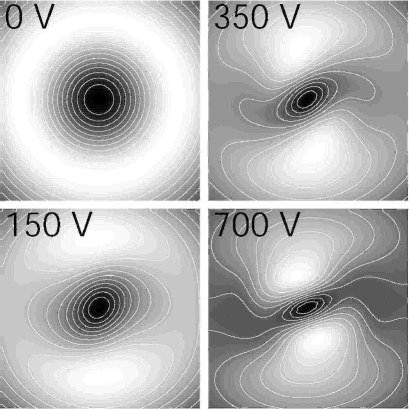
Numerical solutions of Eqs. (2) describing nonlinear evolution of a single vortex () for different values of the applied voltage (nonlinearity) are shown in Fig. 1. The numbers on the frames are the values of this voltage in volts. Superimposed on the images are the equal intensity contour lines visualizing distortions of the vortex core for different values of the nonlinearity. The size of the frames is about .
The input field was taken to be
| (3) |
where is the azimuthal angle, and is the diameter of the Gaussian beam. The parameters of the calculation were the following: the wavelength , the refractive index , the length of the nonlinear medium , the effective electrooptic coefficient , ( Full Width at Half Maximum) and .
The output intensity distribution in the absence of the nonlinearity is given by the frame labeled and corresponds to an annular ring having approximately and internal and external diameters, respectively. The frames corresponding to nonzero nonlinearity demonstrate focusing of the vortex along and its stretching along Also clearly seen is the rotation and alignment of the vortex. This rotation is charge-dependent and changes sign if the charge of the vortex is changed from plus to minus one. The magnitude of all these effects is directly proportional to the value of the applied voltage.
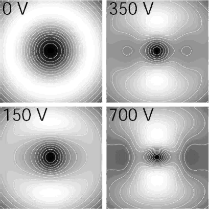
Numerical solutions of Eqs. (2) describing nonlinear evolution of the mutually incoherent vortex pair for different values of the applied voltage (nonlinearity) are shown in Fig. 2. The input field was taken to be
| (4) |
All parameters were the same as in the case of a single vortex (Fig. 1). The parameter was again chosen such that the total maximum input intensity was equal to one (the maximum intensity of each of the constituents of the pair was 0.5). Figure 2 demonstrates some considerable reduction in the magnitude of anisotropy effects as compared to the case of a single vortex (Fig.1). In particular, the degree of ellipticity of the vortex core at high voltages is several times smaller in Fig. 2 than in Fig. 1. The horizontal intensity dip appearing at high intensities on the Gaussian beam and passing from left to right is several times smaller in Fig.2 than in Fig. 1. Figure 2 also confirms that the vortex pair remains stationary and does not translate with respect to the Gaussian beam.
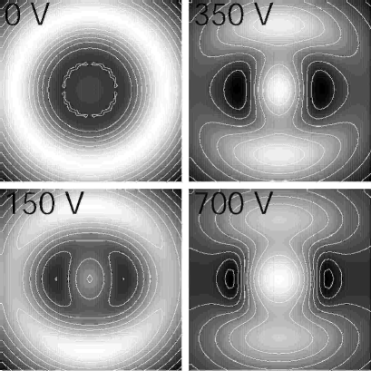
The above stability of the vortex pair is due to its phase structure. To prove this point we have carried out numerical calculations for the input field consisting of two temporal features analogous to Eqs. (4) and (1) but without azimuthal phase dependence
| (5) |
The field (5) has an input intensity distribution that is identical to the above discussed cases but lacks the topological phase structure present in the case of Eqs. (3) and (4). Figure 3 shows results of the calculations. All parameters are the same as in Figs. 1 and 2. In sharp contrast to Figs. 1 and 2 the output distribution of the field does not contain any intensity zeros because of the diffraction. The output intensity for zero applied voltage is a bright ring with a smaller local maximum in the center that is about two times weaker than the ring. Increasing nonlinearity results in the transfer of energy from the ring to the center of the beam and the appearance of two intensity minima on the right and left. The intensity in these minima at the highest value of the applied voltage () is about 0.2 of the maximum intensity in the center.
3 Experiment
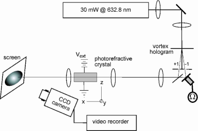
The experimental setup is shown in Fig. 4. A 30 mW He-Ne laser beam () was passed through a variable beam splitter, and a system of lenses controlling the size of the beam waist. Diffraction of the beam by a diffractive element with a fringe dislocation created unit charge vortices of opposite signs in the first order diffracted beams to either side of the transmitted beam. One of the beams was phase modulated by reflection from a mirror mounted on a piezo-electric transducer driven by a sawtooth voltage, such that The beams were then recombined and directed into a photorefractive crystal of SBN:60 doped with 0.002% by weight Ce. The beams propagated perpendicular to the crystal -axis ( axis), and were polarized along it. The crystal measured along the direction of propagation, and was wide along the -axis. The experimentally measured value of the relevant component of the electrooptic tensor was found to be equal to . A variable dc voltage was applied along the -axis to control the value of the nonlinearity coefficient. The crystal was illuminated by a source of incoherent white light to increase the level of the effective saturation intensity. Images of the beams at the output face of the crystal were recorded with a CCD camera.
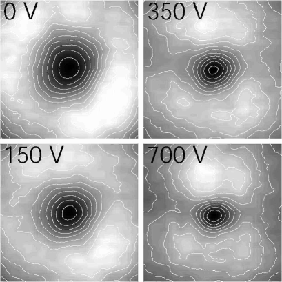
Figure 5 presents experimental output intensity distributions of the light beam with two embedded overlapping mutually incoherent vortices for different values of the applied voltage. The numbers on the frames give the applied voltage in volts. The size of the frames is about m. The output intensity distribution in the frame with no applied voltage corresponds to an annular ring with internal and external diameters of about and m, respectively. Increasing the voltage results in the focusing of the vortex core and its stretching along the direction of the anisotropy which is clearly seen on the last frame corresponding to the V applied voltage. This stretching, however, is much smaller than that for a single vortex for similar parameters. Experimental data on the distortions of a single vortex are given in Ref. [8]. Comparison with the results of the theoretical description shows good quantitative agreement between the experiment and the theory regarding the degree of ellipticity of the vortex core. Positions of intensity lobes (maxima) on the Gaussian beam above and below the vortex core in the theoretical Fig. 3 also are in agreement with those on the experimental Fig. 5.
4 Conclusions
In summary we presented an experimental and theoretical study of the propagation of a mutually incoherent pair of vortices. Incoherent coupling between the oppositely rotating vortices creates a symmetric attractive potential that arrests the rapid spreading and decay of an isolated vortex.
M. S. was supported by the A. P. Sloan Foundation. We are grateful to E. Eilertsen and E. Rasmussen at Risø National Laboratory for preparation of the holographic mask.
References
References
- [1] Ginzburg V L and Pitaevskii L P 1958 Zh. Eksp. Teor. Fiz. 34 1240 [1958 Sov. Phys. JETP 34 858 ].
- [2] Zakharov V E and Rubenchik A M 1973 Zh. Eksp. Teor. Fiz. 65 997 [1974 Sov. Phys. JETP 38 494].
- [3] Mamaev A V, Saffman M and Zozulya A A 1996 Phys. Rev. Lett. 76 2262 .
- [4] Tikhonenko V, Christou J, Luther-Davies B and Kivshar Y S 1996 Opt. Lett. 21 1129 .
- [5] Swartzlander G A, Jr. and Law C T 1992 Phys. Rev. Lett. 69 2503.
- [6] Coullet P, Gil L, and Rocca F 1989 Opt. Commun. 73 403; McDonald G S, Syed K S and Firth W J 1992 Opt. Commun. 94 469; Weiss C O 1992 Phys. Rep. 219 311; Yu S. Kivshar 1993 IEEE J. Quantum Electron. 28 250 ; K Staliunas 1994 Chaos, Solitons & Fractals 4 1783 ; Ackemann T, Kriege E and Lange W 1995 Opt. Commun. 115, 339.
- [7] Lundh E, Pethick C J and Smith H 1998 Phys. Rev. A 58 4816 ; Denschlag J et al. 2000 Science 287 97 ; Madison K W et al. 2000 Phys. Rev. Lett. 84 806 ; Anderson B P et al. 2001 Phys. Rev. Lett. 86 2926; Leanhardt A E et al. 2003 Phys. Rev. Lett. 90 140403 .
- [8] Mamaev A V, Saffman M and Zozulya A A 1996 Phys. Rev. Lett. 77 4544.
- [9] Saffman M and Zozulya A A 1998 Opt. Lett. 23 1579 .
- [10] Mamaev A V, Saffman M and Zozulya A A 1997 Phys. Rev. A 56 R1713 .
- [11] Zozulya A A and Anderson D Z 1995 Phys. Rev. A 51 1520 .
- [12] Aranson I and Steinberg V 1996 Phys. Rev. B 53 75 .
- [13] Mamaev A V, Saffman M and Zozulya A A 1997 Phys. Rev. Lett. 78 2108.
- [14] Lamb H 1932 Hydrodynamics, sixth ed. (Cambridge Univ. Press, Cambridge).
- [15] Saffman M, Benkert C and Anderson D Z 1991 Opt. Lett. 16 1993 ; Saffman M, Montgomery D, Zozulya A A and Anderson D Z 1994 Chaos, Solitons & Fractals 4 2077 .
- [16] Chen Z, Segev M, Coskun, T H and Christodoulides D N 1996 Opt. Lett. 21 1436; Chen Z et al. 1996 Opt. Lett. 21 1821.
- [17] Mamaev A V, Saffman M, Anderson D Z and Zozulya A A 1996 Phys. Rev. A 54 870.