a000000 \paperrefxx9999 \papertypeFA \paperlangenglish \journalcodeS \journalyr2003 \journaliss1 \journalvol59 \journalfirstpage000 \journallastpage000 \journalreceived0 XXXXXXX 0000 \journalaccepted0 XXXXXXX 0000 \journalonline0 XXXXXXX 0000
[a]AndreOrthenorthen@alwa02.physik.uni-siegen.de Wagner Martoiu Amenitsch Bernstorff Besch Menk Nurdan Rappolt Walenta Werthenbach
[a]Universität Siegen, Fachbereich Physik, Emmy-Noether-Campus, Walter-Flex-Str. 3, D-57072 Siegen, \countryGermany \aff[b]Institute of Biophysics and X-Ray Structure Research, Austrian Academy of Sciences, Schmiedlstr. 6, A-8042 Graz, \countryAustria \aff[c]Sincrotrone Trieste, S.S. 14, km 163.5, Basovizza, I-34012 Trieste, \countryItaly
Development of a two-dimensional virtual pixel X-ray imaging detector for time-resolved structure research
Abstract
An interpolating two-dimensional X-ray imaging detector based on a single photon counter with gas amplification by GEM (gas electron multiplier) structures is presented. The detector system can be used for time-resolved structure research down to the -time domain. The prototype detector has been tested at the SAXS (small angle X-ray scattering) beamline at ELETTRA synchrotron light source with a beam energy of . The imaging performance is examined with apertures and standard diffraction targets. Finally, the application in a time-resolved lipid temperature jump experiment is presented.
keywords:
Micro pattern gaseous detectorskeywords:
Time resolved X-ray imagingkeywords:
Two dimensional detectorkeywords:
Small angle X-ray scatteringkeywords:
Lipid phase transition1 Introduction
Modern synchrotron radiation facilities are able to provide extremely high photon fluxes with an enormous brilliance, which opens up new research fields in many different areas. One of these branches are fast time-resolved studies. Of special interest are for example dynamical processes in material science [Clery] like phase transitions, polymerisation or deformations under stress. In the chemical or biological domain for example muscle contraction [Squire, Wakabayashi, Holmes, Piazzesi] or lipid phase transitions [Rapp1992, Seddon] come into the focus of interest.
However, the existing X-ray detectors do not offer the time-resolutions needed or are often not capable of dealing with the enormous photon rates produced by insertion devices like wigglers, undulators or in future by free electron lasers, and are the bottleneck of state of the art beamlines. To find a solution for this mismatch one has to improve old detector concepts or to introduce new approaches.
Detectors in general can be classified into two categories: integrating detectors and single photon counters. The performance of integrating devices like CCDs (charge coupled devices), image plates or X-ray films, is getting more favourable at high photon flux, since the relative noise contribution is decreasing. The noise contributions can be attributed to noise caused by fluctuations of the measured quantity related to the input (intrinsic noise), to dark noise and to readout noise. The readout noise increases in proportion to the readout frame rate, whereby in most CCDs this noise contribution is much larger than the dark noise. Time-resolution is thus competing with intensity precision; generally, the time-resolution is limited to keep the readout noise contribution relatively small. At some value of input flux the integrator saturates and can not add up more until the content is reset. The dynamic range of integrating devices, which is typically –, is thus limited by noise and saturation level.
In contrast to integrating devices counting detectors like MWPCs (multi wire proportional chambers) or MSGCs (micro strip gas chambers) are not sensitive to noise contributions, described above, as long as this noise level is below the threshold, triggering the counter. However, one single event implies a dead time, for instance caused by the length of the produced detector signal and the electronic processing, e.g. the readout. Due to this dead time the performance of counting detectors drops at high rates and dead time corrections have to be applied to correct the measured intensities. Especially when counting detectors are used in synchrotron radiation facilities, these corrections can become complicated due to the intrinsic time structure of the photon beam [Bateman]. The dynamic range of photon counting devices, typically reaching values of up to , is limited downwards by the number of counts due to false triggers (noise triggers) and upwards by the (inverse) dead time. To prevent the detector from too high photon rates one has to attenuate the primary beam, and thus the full power of modern synchrotrons is wasted. Due to the low noise level, the high dynamic range and the good time-resolution, which can be approximately in the order of magnitude of the dead time or even better, single photon counting detectors, e.g. one-dimensional delay-line detectors [Gabriel], are often used for example in SAXS imaging, where only small parallax is obtained due to the small diffraction angles.
However, the unique detector for every application is not existent and compromises have to be found, optimising the detector for the particular application. Although many efforts have been started to increase the readout speed of integrating CCD cameras, e.g. [Tipnis], the time-resolution is still limited to about . Despite their good spatial resolution and their large number of pixels CCDs also suffer from the limited intensity precision of roughly [Kocsis] and the limited dynamic range. On the other hand, single photon counters can still not deal with the enormous rates offered by synchrotron facilities.
There are new ideas to find solutions to this drawback e.g. with semiconducting pixel array detectors [Datte, Rossi, Renzi]. With the introduction of micro pattern gaseous devices like MSGCs [Oed] or GEMs [Sauli] several new approaches have been carried out building faster gaseous detectors, e.g. the RAPID (refined ADC per input detector) system [Lewis1994, Lewis1997, Lewis2000] or a GEM pixel detector [Bellazzini], which replace the old detector era of MWPCs. An overview of micro pattern gaseous detectors can be found for example in [Sauli1999].
The two-dimensional single photon counting gaseous detector for X-rays in the energy range of –, described in this work, represents a concept which is very flexible and can therefore easily be adapted to special requirements. It offers time-resolutions in the sub-microsecond range and is thus qualified for time-resolved SAXS-imaging.
2 Detector setup
In this section we briefly describe the working principle and the setup of the detector. Detailed information about the detector can be found elsewhere [Besch, Sarvestani1998b, Wagner2003, Orthen2003b]. A review of a previous, similar detector with smaller sensitive detection area and a less sophisticated position reconstruction, with a different gas gain structure and with slower electronics and readout has also been published earlier [Sarvestani1999b].
Fig. 1 shows a schematic cross-section of the detector. The X-ray photons enter the detector through the carbon fibre entrance window and the subjacent thick mylar foil clad with a few micrometer thick carbon layer at the bottom side serving as drift cathode. Inside the conversion region between the drift cathode and the (first) gas gain structure (gap of about , which is a compromise between a good photo effect efficiency and moderate parallax) one single photon produces a few hundred primary electrons in the gas volume, which is typically filled with (90/10).
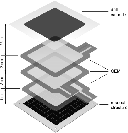
Since this charge amount is too small to be detected additional amplification is necessary. For that purpose micro pattern devices like MicroCAT (micro compteur à trous) [Sarvestani1998a] or GEM [Sauli] have been intensively tested [Sarvestani1999a, Orthen2002a, Orthen2003a, Orthen2003b]. The MicroCAT has many advantages like stable gas gaining at high rates, time stability or an enormous robustness. Nevertheless, we were not successful in finding a suitable spacer concept which should guarantee a constant distance to the subjacent readout anode. Therefore, we decided not to use this device. For the GEM an external spacer concept is not necessary and, despite some disadvantages like rate- and time-dependent gas gaining which are discussed in Sec. 3, we have decided to use a constellation of three consecutive GEMs (triple-GEM).
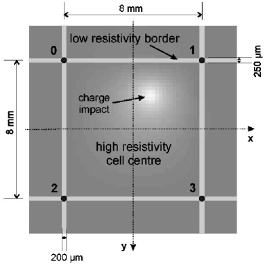
After multiplication the charge cluster hits the readout anode, which is realised by an interpolating resistive structure, where the spatial information of the event is determined in two dimensions [Besch]. The sensitive area of the readout structure is divided into square cells. Each cell (Fig. 2), which has an edge length of and a surface resistance of , is surrounded by better conducting borders with a width of about and a surface resistance of . The resistive material is printed onto a ceramics or a PCB medium, based on FR4. The charge flows to the readout nodes at the corners of the cells, which are connected by small through connections to the backside of the readout structure. By means of linear reconstruction algorithms, e.g. using only the collected charges at the four readout nodes of one cell (4-node algorithm), the event position can be calculated within the cell. For a proper reconstruction using combinations of several linear algorithms (463-node algorithm) always 9 nodes should be read out [Wagner2003].
Due to this interpolating concept the cells can be subdivided into Virtual Pixels (ViP) and a large sensitive area can be covered, simultaneously reaching a spatial resolution of the order of (fwhm) which is nearly two orders of magnitude better than the size of a cell (this spatial resolution can only be obtained in combination with adequate electronics and a gas gain of about since the spatial resolution is directly proportional to the reciprocal signal to noise ratio ).
Each read out charge is amplified by a charge sensitive amplifier and digitized by a ADC (analog to digital converter) sampling with a frequency of . Four ADC-channels corresponding to one detector cell are placed together at one ADC-card, where they are connected to one complex Xilinx FPGA (field programmable gate array) logic device [Nurdan2003]. Via point to point links the sixteen ADC-cards, containing all 64 channels, can communicate with their direct neighbours, while the data/control bus supports the communication with a master card, controlling the data latch to the PC (Fig. 3).
Together with the signal information a time stamp in terms of a - or -counter is digitally recorded. The counter can externally be reset. Additionally, an external signal (e.g. a linear ramp) can be digitised by the ADC at the master card. The time information can be used to slice the data after the measurement has been finished.
The digitised data from the ADC-cards are stored into a FIFO inside the Xilinx on the master card, which is connected via optocouplers to a PC using a standard PCI-interface. Currently, the transfer in DMA-mode can latch data with a speed of into the memory of the PC. By using an alternative PCI-card the transfer speed can even be increased to . A dedicated software package, written in Visual C++, processes data online, so that the user is directly able to evaluate the running measurements. The raw data as well as the already processed image histogram can be stored to hard disk. Each event occupies in the raw data file.

3 Detector performance
3.1 Gas gain
Each individual GEM foil produces a gas gain of about –, if the GEM operation voltage amounts to about – depending on gas mixture and pressure. The total gas gain of a triple-GEM constellation can easily exceed and stable operation in xenon gas mixtures up to at this gain is possible [Orthen2003b]. Operation with pressure with high- gases like xenon is not advisable due to a high discharge probability at gains . The use of the triple-GEM for hard X-ray detection () is therefore rather limited.
Since the GEM technology is well sophisticated and intensively tested also large area GEMs can be built [Bachmann2000] and thus large sensitive areas are feasible.
The gain homogeneity over the total area of the triple-GEM constellation at uniform illumination is much superior to MicroCAT detectors because no external spacer concept is needed due to the intrinsic constant thickness of the Kapton foil and the width of the multiplication gap, respectively. Disadvantageous is the fact that the GEM can easily be destroyed by too heavy sparks. To avoid the destruction, large area GEMs should be subdivided to reduce the capacitance of the individual sectors [Bachmann2000, Bachmann2002b]. The detector should always be operated in safe voltage and gas gain ranges, if possible.
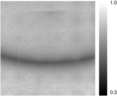
Due to charging up of the Kapton, the gas gain drops as a function of illumination time and rate. As an example, Fig. 4 shows the measured relative gain distribution as a function of the position in the detector during the measurement of a silver behenate diffraction target with high local rates (cf. Sec. 4.3.2). In counting detectors, like the detector presented here, a rate- and time-dependence of the gas gain is not relevant as long as the signals do not drop under the trigger threshold. However, an energy selectivity can not be carried out for inhomogeneous images and due to the decreasing signal-to-noise ratio also the spatial resolution drops in highly illuminated areas. This has to be compensated by a very high overall gas gain (which is easily possible with the triple-GEM) but which requires a high dynamic range of analogue and digital electronics. Due to the time- and rate-dependent behaviour the GEM can not be used as a preamplification stage in integrating systems, as planned for the MicroCAT device [Menk1999]. To stop the charging of the Kapton and thus to keep the gas gain rate- and time-independent a coating of the GEM with amorphous carbon is proposed [Beirle]. The energy resolution of the triple-GEM then is expected to be in the order of at , which can also be obtained with standard (uncoated) GEMs in homogeneous illumination or single photon spots with constant X-ray flux after an equilibrium state has been reached.
3.2 High rate capability
In counting detectors one has to make a compromise between high rate capability and spatial resolution. In general a detector can be optimised to deal with high rates by a very fast shaping of the analogue signals, at the same time, however, losing spatial resolution due to too little collected charge and thus a too small SNR. The most elegant way to avoid these problems is to produce very short intrinsic detector signals, which is one big advantage of micro pattern devices in contrast to MWPCs. The GEM features a very fast signal shape at the anode, which is induced only by electrons. The about -times slower ions do not make any contribution to the signal, which is however the case for other micro pattern devices like MicroCAT or micromegas (micro mesh gaseous structure) [Giomataris1996]. In our detector setup the raw anode signals have approximately a gaussian shape with a mean length of – (fwhm) for (90/10) at standard pressure and (90/10) at a pressure of , respectively [Orthen2003b].
The relatively high resistance and capacitance of the sensitive area leads to an integrating -element-like behaviour of the readout structure, resulting in a temporal broadening of the input signal (Fig. 5). After the signal information has crossed the cell from the point of impact towards the readout nodes, the total signal width has increased.

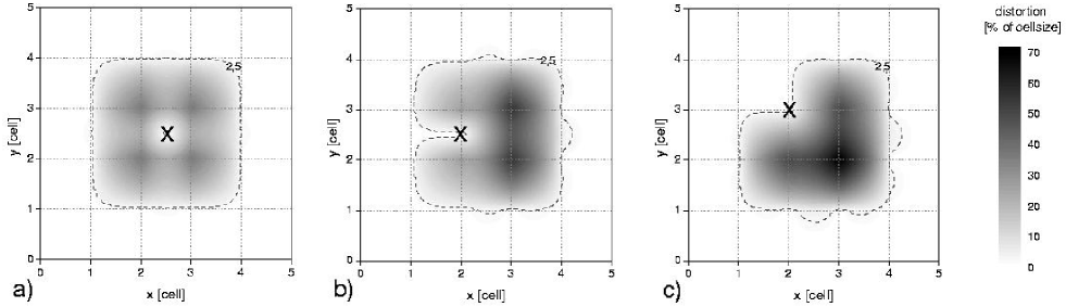
Due to the interpolating character of the image reconstruction we have to make sure, that the signals do not pile up in a certain area. Affected by this constraint is at maximum an area of cells containing the cell with the charge impact as the central area (Fig. 6). In this simulation the reconstruction is carried out with a simple 4-node algorithm, using only the charges collected at the four central nodes. This is a worst case estimation for two contemporaneous events. The later the second event appears within the dead time window of the first event the smaller is the distortion. With a typical amplified signal having a length the average detected flux is limited to with less than dead time loss. This value corresponds to an average detected flux of about for a detector with a cellsize of , which is a true value. This means, that the global count rate capability is the product of the average detected flux and the total size of the detector. Note that apart from pure pixel devices, a similar principle limitation in local rate capability is found for all interpolating devices, although it is often not explicitly mentioned. Often one finds a mismatch between the global rate capability and the number given for the average detected flux multiplied by the active area of the detector. This is not the case for the numbers given in this work.
Since the arising dead area is always measured in cell units a decrease in cell size leads to a higher average detected photon rate per unit area. By decreasing the cell size for instance to , the average detected flux increases by a factor of 16 to . In principle, one is free to adapt the cell size to be able to deal with the desired photon rates. However, the cell size is limited upwards by the deteriorating spatial resolution and the signal diffusion, which increases nearly proportional to the square of the cell edge length (this result was obtained by simulations [Wagner2004]). Decreasing the cell size is limited by the readout speed of the electronics which can not be exceeded. Moreover, if the cell size is chosen too small (), the advantage of the interpolating readout system vanishes; in this case, a pure pixel device is much more advantageous and easier to handle. By means of a complex signal recognition double events may potentially be processed properly in future, which would improve the local rate capability enormously. Yet, this feature has not been investigated.
Another rather critical point in gaseous avalanche detectors is the influence of space charge produced by the multiplication process – mainly of the slowly drifting ions –, causing spatial reconstruction distortions, because the electrons, drifting from the conversion gap towards the gain regions, are attracted by the ion space charge. A big advantage of micro pattern devices compared to e.g. MWPCs is the fact, that the amount of ions, drifting back from the multiplication regions to the drift cathode, is relatively small. In case of the triple-GEM we have measured an ion feedback [Orthen2004]. With special care in choosing the parameters of the GEM it should be possible to suppress the ion feedback to less than at a gain of [Breskin, Bondar2003], but this has still to be proven experimentally. For the MicroCAT in combination with the resistive readout structure we have measured no serious degradation in operation due to space charge at photon peak fluxes with a beam collimation of . Also the GEM can work with high local fluxes [Ostling].
3.3 Noise level and intensity precision
The noise level of the triple-GEM detector is around a few counts per seconds over all the sensitive area, as typical for counting detectors. For a virtual pixel interpolation, corresponding to a pixel size of , the noise level is far below . Intensity precision is thus, as expected, only Poisson-limited and can be better than .
3.4 Analogue Electronics
The charge integrating preamplifiers with subsequent shaping, currently in use, have a shaping time of . They have not been optimised for this application, but were rather built for a MWPC which produces signals with long ion tails. In the future we plan to use a linear transimpedance preamplifier. The charge collection by current integration can be carried out digitally afterwards in the FPGA. One prototype channel which has already been tested responds to a -like input with a gaussian signal shape with a width of about (fwhm) due to bandwidth limitations.
3.5 Preprocessing and data readout
The data readout crucially influences the dead time behaviour of the overall system. In a previous version of the electronics [Stiehler1998] the data transfer used to be the bottleneck of the readout, which limited the readout speed dramatically and implied additionally an electronic dead time of about per event. The synchronous readout was triggered by an externally generated signal (“global trigger”) which was created by the discriminated signal from the bottom side of the lowermost GEM (or from the MicroCAT, respectively).
The newly developed very modular ADC system enables a parallel and asynchronous readout of the nine nodes of interest, carrying the most important information of one event. Furthermore, it offers the capability of preprocessing before data are latched to the PC. The processing is performed by Xilinx FPGA devices which are freely programmable using a hardware description language like VHDL. The new system is, for example, able to integrate the current signal, to find the signal peak and to locate the node with the maximum signal and the surrounding 8 nodes autonomously. Furthermore, it can work in a self-triggering mode, i.e. a trigger is generated by a signal recognition unit. This trigger signal needs not serve as a global but rather as a “local” trigger which means that only the region of interest is triggered for readout while the neighbouring channels (at least two cells away) are not read out and thus work in a normal fashion. During the readout of the 9 nodes of interest the participating ADC channels are continuously sampling new data, so that no additional dead time occurs. For the final version of the local trigger programming we expect that the dead time contribution due to the readout is small compared to the signal lengths [Martoiu].
Due to the modularity, an upgrade of to a larger system can be realised by a replication of the system, described above. The master cards of these sub-systems have to be connected to an overall-master. Thereby, it should be possible to extend the detector by scaling the sensitive area and the global rate capability at the same time without loss of spatial resolution and local rate capability. When the number of electronic channels exceeds a certain limit, the whole reconstruction work should be implemented in the FPGA logic devices on the system master-card(s) by making use of the newest generation of FPGAs featuring fast multiplier/divider units. By only transmitting the (already time-sliced) histograms instead of the raw data the data transfer to the PC will be compressed by several orders of magnitude.
Unfortunately, the measurements, described in this publication, could only be carried out with a “slim” version, which means that the Xilinx devices were programmed with a less complex test mode VHDL programme. It is still based on a global trigger which is distributed to the whole system by one dedicated ADC-channel, that originally used to digitise data at the corner of the sensitive area (cf. black dead area in the lower right corner of Fig. 10). After the trigger has been received by the other ADC-cards, the peak sampling point in a defined time window of each channel is transmitted to the master card that decides which 9 nodes are sent to the PC. The dead time of this procedure amounts to about . The local trigger programming is currently under development, and a simple prototype version has already been tested successfully.
3.6 Time-resolution
With the triple-GEM detector and the new digital (and analogue) electronics it seems sensibly feasible to reach continuous time-resolutions in the -range; thereby, the time-resolution is limited by the width of the conversion gap : Incoming photons may convert into electrons by photo effect everywhere in this gap (actually more photons convert directly behind the entrance window compared to positions directly above the GEM due to the exponential absorption law). By this physical process the time-resolution is limited by the maximum electron drift time in the conversion gap. Typical values for the electron drift velocity are in xenon-based gas mixtures at standard pressure [Becker]. This means, that the time-resolution is limited to about for a conversion gap. The drift gap can be chosen smaller, at the same time losing quantum efficiency. Increasing gas pressure to increase efficiency will decrease drift velocity and hence increase the drift time. Maybe the addition of to the xenon mixture can increase the electron drift velocity [Va'vra]. Simulations with the Magboltz programme show promising results [Magboltz2].
The limitation of the time-resolution, described above, is actually similar in all gaseous devices where a larger conversion gap is needed to gain sufficient quantum efficiency. Incidentally, the timing structure of the synchrotron beam caused by the individual electron bunches in the storage ring is also lost due to the slower electron drift in the conversion gap; for ELETTRA or ESRF the minimum time difference between two bunches (with uniform bunch pattern) amounts to about .
4 Imaging performance
The images, shown in the next subsections, have been recorded with two different readout structures based either on a ceramics or on a printed circuit board (PCB). Both substrates have advantages and disadvantages:
The -ceramic medium is very planar and therefore well suited for operation with a MicroCAT gas gain structure. However, it suffers from a high dielectric constant () leading to a large capacitance of the resistive area and therefore to a large signal diffusion at the readout structure (cf. Sec. 3.2). Furthermore, the through-contacts have a relatively large diameter of –, leading to image distortions in the surrounding area of the nodes.
The newly introduced PCB structure is not planar and hence not suited in combination with the MicroCAT without a sophisticated spacer concept. In combination with the triple-GEM, however, the advantages outbalance the ceramics due to the lower dielectric constant (), the possibility to use micro-vias at the readout nodes with a diameter of only and the very flexible multi-layer configuration.
4.1 Flatfield response
Due to a slightly non-linear behaviour of the ViP readout structure it is not possible to reconstruct distortion-free images with only one linear algorithm. Fig. 7 a) shows the response of a detector with a PCB-readout structure to a uniform illumination reconstructed with a simple 4-node algorithm. A -source has been used for illumination (). The detector has been operated with an (70/30) gas filling at a pressure of . The depletion at the cell border shows the non-linear charge division behaviour. By using a more complex linear 4/6/3-node algorithm [Wagner2003] these kind of distortions do not occur anymore (Fig. 7 b)). However, the population density is still not flat as it should be (i.e. the nodes are overpopulated) due to systematic effects like cross talk, electronic gain variations111Gas gain variations displace the event position only far less than the value of the spatial resolution [Orthen2000]., variations of the resistance of the sensitive area or the width of the low resistivity cell borders or simply signal fluctuations due to noise [Wagner2004] . To further improve the image one can apply a non-linear correction (two-dimensional variable transformation), resulting in an image shown in Fig. 7 c).
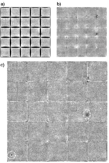
All further images have been reconstructed with the linear 4/6/3-node algorithm with a global non-linear correction at the nodes and at the cell borders.
4.2 Aperture image
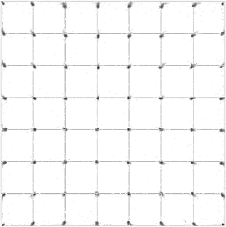
4.2.1 Hole grid collimator
The image of a hole grid collimator consisting of a stainless steel aperture with holes at a grid distance of is depicted in Fig. 8. It becomes obvious, that close to the border of the detector the image is slightly distorted. These distortions are mainly caused by a slightly inhomogeneous drift field and can be avoided by the usage of an additional electrode frame which is fixed upon the ceramic frame, holding the uppermost GEM. Distortions due to field inhomogeneities can also be caused by inhomogeneous electric fields between the individual GEMs (transfer field) and between undermost GEM and readout structure (induction field). It is very important that the distance between the individual electrodes is as constant as possible. Especially the transfer and induction fields are very sensitive to these variations due to the small distance of – of the particular electrodes. Transfer and induction field variations are also a possible reason for global gas gain variations because the effective gas gain is determined by the electron transfer through the GEM holes which is strongly affected by the electric fields close to the GEM structures [Orthen2003a].
4.2.2 SAXS collimator
Fig. 9 shows the image of a laser cut thick stainless steel aperture containing “SAXS 2D” letters and five holes with increasing hole diameters. The image has been recorded with a PCB-readout structure using photons of an energy of (fluorescence of a Fe-target in a synchrotron beam). The detector was filled with a (90/10) gas mixture at a pressure of . The comparison to a photographic image of the aperture (right hand side image in Fig. 9) shows a very good accordance. Only the middle part of the second “S” (dashed circle) looks slightly distorted; at this readout channel the preamplifier was not working fully correctly and causes slight distortions in all images shown. The reproduction of the small holes shows a good agreement, too. The remaining spots (dotted circles) are most likely due to a non-optimised flatfield correction.
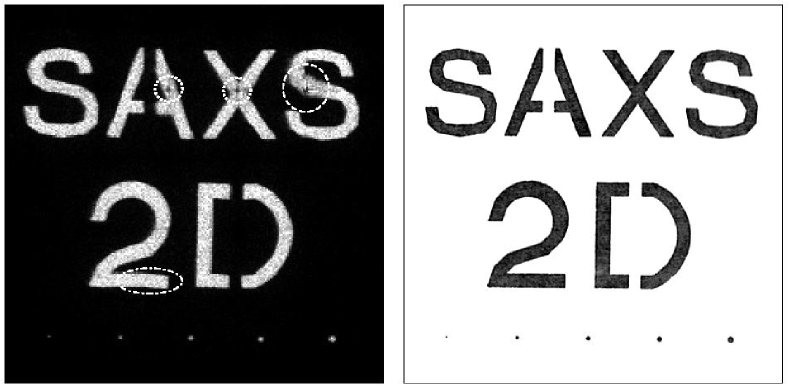
Using the image of the smallest hole of the SAXS aperture with a diameter of , we have determined the width of the point spread function (psf) to be in the order of (fwhm).
4.3 Diffraction measurement
All diffraction patterns, presented in the following, have been recorded at the Austrian SAXS beamline [Amenitsch, Bernstorff] at the synchrotron ELETTRA/Trieste.
4.3.1 Rat tail tendon collagen
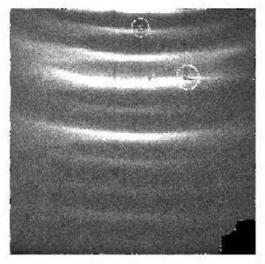
Fig. 10 shows the diffraction pattern of a rat tail tendon with a -spacing of about which was used for the detector calibration/alignment for the time-resolved SAXS measurements described in Sec. 5 The image has been recorded with a ceramic readout structure and a beam energy of ; the remaining detector parameters were the same as described in Sec. 4.2.2 The vertical intensity profile is shown in Fig. 11. Even the and diffraction order are slightly visible.

4.3.2 Silver behenate
Another standard diffraction target in the small angle region, silver behenate with a -spacing of [Blanton], has also been recorded with the ViP detector system. The depicted image, composed of individual images, is shown in Fig. 12.
5 Time-resolved SAXS
Several mechanical test measurements in our laboratory have been carried out with a X-ray tube showing the capability of the detector system to resolve very fast repetitive processes up to the -regime [Sarvestani2001]. Since a slower electronic system has been used for these measurements the processes had to be periodically repeated a few hundred or even a few thousand times to collect sufficient statistics. A repetition is no problem at radiation stable materials which have been used for these measurements. However, the number of repetitions in e.g. biological X-ray diffraction measurements is limited due to severe radiation damage of the sample.
Here, we present a time-resolved temperature jump experiment of a 1-palmitoyl-2-oleoyl-sn-phosphatidylethanolamine (POPE) lipid. The sample preparation is described elsewhere [Rappolt2003]. The sample has been placed inside a thin-walled quartz capillary with a diameter of . The -jump has been induced by a light flash from a solid state laser at a wavelength of with erbium in glass as the active laser medium [Rapp1991]. We have repeated the experiment about ten times, which was sufficient due to the high scattering power of the sample and since we were not interested in intensity resolution but rather in the change of the -spacing in the lipid due to the rapid temperature increase, manifested by a spatial displacement of the diffraction ring.
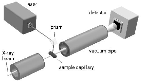
The sketch of the experimental setup is depicted in Fig. 13. The prepared lipid sample in a capillary device has been mounted at the intersection point of the infrared laser beam and the monochromatic X-ray beam. A water-based cooling system combined with a heater (KHR, Anton Paar, Graz, Austria) assured a constant starting temperature of the sample which can be chosen within a temperature range of –. The sample temperature has been measured with a platinum resistor PT-100. Before the -jump, the sample was equilibrated for a period of about at a fixed temperature. The flash-like laser pulse with a length of and a measured pulse energy of appears about after the trigger pulse and heats the sample very rapidly by approximately . We have collected data for a period of up to starting about before triggering of the laser pulse.
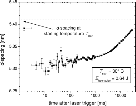
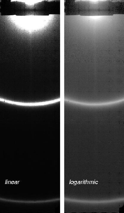
After the measurement the data have been cut into fine time slices (e.g. -slices for , where denotes the time after the laser trigger). For the data analysis we have carried out a radial integration of the two-dimensional intensity histogram (the rat tail tendon image was used for the determination of the beam centre at the detector) and a subsequent lorentzian maximum-likelihood fit to the peak. The result of the reconstructed lipid -spacing as a function of time after the laser trigger of one recorded -jump is shown in Fig. 14. It is clearly visible that the temperature increase of the lipid features a decrease in -spacing. More detailed results concerning the -jump of the POPE lipid will be published later.
6 Conclusion
The GEM-based ViP photon counting prototype detector represents a powerful tool for time-resolved X-ray imaging applications in the or even the -range [Sarvestani2001]. The most important parameters are summarised in Tab. 1, where also a possible future version of the detector and a comparison to the RAPID detector is listed. Large sensitive detection areas in combination with spatial resolution in the order of are feasible with the virtual pixel readout concept, at the same time saving expenses due to an enormous reduction of electronic channels. Since the GEM produces short signals the detector can deal with high local rates without signal pile-up; average detected fluxes of with less than dead time losses are easily possible. The rejection of multiple events in an area of approximately cells around the position of the photon impact could possibly be overcome in future by a more complex signal processing. It is expected, that the electronic local trigger concept – enabling an asynchronous readout – will be capable of dealing with very high rates so that the global rate capability is proportional to the number of cells and the sensitive area, respectively; nevertheless, this has still to be tested. The ViP detector offers a high quantum efficiency and a relatively good parallax suppression even for higher photon energies up to about since high pressure operation up to 2– in Xenon-mixtures is possible. The overall time resolution, which is mainly determined by the electron drift time in the conversion gap, is at minimum in the order of a few and thus in the sub--range.
| ViP (present) | ViP (future) | RAPID | |
|---|---|---|---|
| Detector type | Triple-GEM | Triple-GEM | Wire microgap |
| Active area | |||
| No. of cells | - | ||
| Cell size | - | ||
| Detected peak flux | |||
| Average detected flux | |||
| Global counting rate | |||
| Gas filling | |||
| Conversion gap | |||
| Efficiency | |||
| No. of pixels | adj., typ. | adj., typ. | adj., typ. |
| No. of electronic channels | |||
| Spatial resolution | fwhm | fwhm | fwhm |
| Noise level | |||
| Time resolution | |||
| Spectral resolution | sufficient for triggering |
Acknowledgements
We gratefully acknowledge the help of D. Junge who assisted in equipping the new electronics. We thank the inner tracker group of the HERA-B collaboration for providing several GEM foils.
This work has been supported by the European Community (contract no. ERBFMGECT980104).
[reflist]