Optical trapping of absorbing particles
Abstract
Preprint of:
H. Rubinsztein-Dunlop, T. A. Nieminen, M. E. J. Friese, and N. R. Heckenberg,
“Optical trapping of absorbing particles”,
Advances in Quantum Chemistry 30, 469–492 (1998)
Radiation pressure forces in a focussed laser beam can be used to trap microscopic absorbing particles against a substrate. Calculations based on momentum transfer considerations show that stable trapping occurs before the beam waist, and that trapping is more effective with doughnut beams. Such doughnut beams can transfer angular momentum leading to rotation of the trapped particles. Energy is also transferred, which can result in heating of the particles to temperatures above the boiling point of the surrounding medium.
pacs:
42.62.Be,42.62.Eh,42.25.Fx,42.25.JaI Introduction
The availability of lasers has enabled the observation of forces due to light interacting with microscopic objects. In 1970, Ashkin ref1 reported optical trapping of micrometre sized spheres using two opposing laser beams, and by 1980 ref2 had proposed many experiments using focused laser beams, and discussed widely varying possible applications, including automatic force measurement, particle size measurement using surface wave resonances in scattering particles, a modified Millikan experiment, measurement of radiometric forces, and separation and manipulation of biological particles. In 1986 ref3 the single-beam gradient optical trap, or optical tweezers was first demonstrated. Optical tweezers can be used for three-dimensional manipulation of transparent particles around 1–100 µm in diameter, or other small particles which behave as reactive dipoles.
The single-beam gradient optical trap consists of a single laser beam, tightly focused to create a very strong field gradient both radially and axially, which acts on polarisable particles to cause a dipole force. Polarisable particles are attracted to the strongest part of the field, at the beam focus, due to the gradient force. A scattering force results from momentum transfer to the particle when light is scattered by it. Under the right conditions the gradient force can balance the scattering and gravity forces, to trap particles three-dimensionally in the laser beam. If the laser beam is not tightly focused, the axial component of the gradient force will be weak, and only radial trapping will be possible ref1 ; ref4 .
A practical optical tweezers setup usually consists of a laser beam with a power of a few hundred mW, introduced into a microscope and focused using a high numerical aperture objective lens. Both conventional upright and inverted microscopes are used, the inverted microscope providing stronger axial trapping due to the scattering force opposing gravity.
The ability to manipulate transparent particles of size 1–100 µm in a closed sterile environment has been exploited by researchers in the biological sciences, to move ref5 , isolate ref6 ; ref7 , cut (using UV beams, where biological specimens are highly absorbing) ref8 , and perform surgery on cells ref9 and to do various forms of analysis. The very high intensity region at the beam focus can be used for two photon spectroscopy, which enables analysis of very thin sections of a sample, since the high intensity region is extremely localised ref10 . Using calibrated forces from optical tweezers, it is also possible to measure physical properties of specimens, such as the compliance of bacterial flagella ref11 , mechanical properties of a single protein motor ref12 and tube-like motion of a single polymer chain ref13 .
Although the particles normally trapped with optical tweezers are highly transparent, there is usually some absorption occurring. Studies have been made of the wavelength dependence of the heating of specimens and the ability of live specimens to remain viable after having been trapped ref14 ; ref15 ; ref16 .
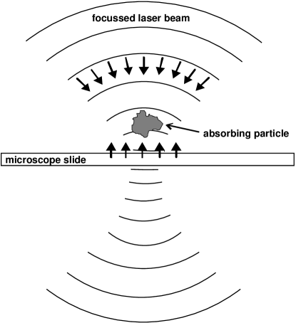
Svoboda and Block ref17 reported that small metallic Rayleigh particles with sizes on the order of tens of nm can be trapped using dipole forces. However when the absorptivity of micron-sized particles becomes high enough, radiation pressure becomes much greater than the gradient force, and they can no longer be trapped using dipole forces. These absorbing particles are then affected primarily by radiation pressure, whereby the momentum of the absorbed light is transferred to the particle. The momentum of the light field is normal to the wavefronts, so if the curvature of the wavefront is such that the resulting force can be resolved into a radially inward force and a force in the direction of beam propagation, then particles constrained in the direction of beam propagation (e.g. by a glass microscope slide as in Figure 1) can be trapped two-dimensionally.
Trapping of micron-sized reflective particles has been modelled in a similar way ref18 . On the basis of ray optics, a totally reflective particle can be shown to be radially constrained when located before the beam focus. However, the forces produced by reflection are dependent on the angle at which the laser light impinges on the particle. Trapping of absorbing particles is much less dependent on particle geometry as the radiation force is perpendicular to the wavefront and independent of the orientation of the particle surface. In experiments on the trapping of microscopic reflective particles, heating effects such as bubble formation and radiometric forces were observed ref18 , indicating a noticeable absorption effect, so absorption of linear momentum also contributes to the trapping forces acting on these particles.
Using such transfer of linear momentum, absorbing particles such as zinc dust ref19 , CuO particles ref20 and ceramic powder ref21 ; ref22 have been trapped and manipulated. The laser beam used in most of these experiments was equivalent to a Gauss–Laguerre LG03 mode, a doughnut beam. When a doughnut beam is used for trapping, the laser intensity is concentrated in a ring of light: this means that the radiation force along the beam axis is less than for a TEM00 mode, and the radiation trapping is comparatively stronger.
As well as linear momentum, angular momentum is transferred from light to absorbing particles during trapping. Both orbital angular momentum due to the helical wavefront of a LG03 mode ref19 ; ref21 ; ref23 and spin angular momentum due to the polarisation of the light ref19 ; ref23 ; ref24 have been observed to set particles into rotation.
In this paper we review the work performed on absorbing particles. Both Gaussian and Laguerre–Gauss modes are commonly used. We outline a model for the trapping of absorbing particles for these beam types based on the effects of transfer of momentum from the beam to the particle. We also consider in some detail the heating effects.
II Laser tweezers experiments
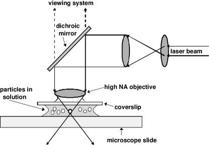
The most commonly used experimental set up (depicted in Figure 2) for the single beam optical trap is optimised for trapping transparent particles and consists of a laser light source directed into a port of an optical microscope ref25 . A variety of lasers can be used for trapping, ranging from He-Ne lasers, CW NdYAG lasers, Ti Sapphire, Ar ion lasers to diode laser sources ref26 ; ref27 ; ref28 ; ref29 ; ref30 ; ref31 ; ref32 ; ref33 . A single mode laser beam is introduced into the microscope in such a way as not to interfere with normal microscope function. It is brought to a tight focus at (or near) the specimen plane, usually with a high numerical aperture () oil immersion objective lens. As microscope optics are designed to minimise aberrations near the specimen plane, arranging the optics in such a way that the trap is parfocal with the specimen allows trapped objects to be visualised and improves the quality of the trap. High numerical aperture is essential to maximise the light intensity gradient near the focal plane and ensure stable trapping in the axial direction. The diameter of the laser beam is normally expanded just before being introduced into the microscope using a set of appropriate lenses. This is done in order to ensure exactly filling, or somewhat over-filling the back pupil of the objective lens. In this way minimum focal spot size and maximum intensity gradient, and hence the strongest trapping force on an object to be trapped and manipulated is achieved. The expanded beam is deflected to the objective by a dichroic mirror. The spot size of the laser beam is of the order of 1–2 µm at the focal plane of the microscope.
Particles to be trapped are placed between a microscope slide and coverslip. Depending on the type of particle, the solution in which they are kept varies (water, kerosene etc). The optical trapping is observed using a CCD camera mounted on the microscope.
In most experiments the trap has to be moved with respect to the specimen. This can be done by either moving the specimen or by moving the beam ref34 . A specimen can be positioned in the -plane by moving the microscope stage in the conventional way, leaving the trap fixed on the optic axis. When small precise displacements are needed, the sample can be mounted on an piezoelectric stage which is computer controlled. Movement of the trap in the -direction (depth) is achieved by focusing the microscope up or down, taking advantage of the parfocality of the trap and specimen. The -direction movement can also be made in extra fine steps if either the sample or the objective is placed on a vertical piezoelectric element. A change in the vertical position of the trap with respect to the specimen plane can be achieved by moving an external lens which controls the beam divergence. A large number of experiments involving the trapping of transparent objects with refractive indices higher than the surrounding medium have been performed using the above described set-up [for reviews, see ref35 ; ref36 ; ref37 ; ref38 ].
For transparent (non-absorbing) objects, the strongest trapping is achieved at the beam waist which is near the object plane of the microscope lens and therefore trapped particles are in focus when viewed. The forces acting on the trapped particle have been studied by calibrating against viscous drag exerted by fluid flow using escape-force methods ref25 ; ref26 ; ref29 ; ref39 ; ref40 ; ref41 . The force can also be measured as a function of displacement from the trap centre. In this way, the trap stiffness, when the particle in a single-beam gradient optical trap is modelled as a mass in a 3-D (ellipsoidal) harmonic potential well ref42 ; ref43 ; ref44 , can be determined.
II.1 Absorbing particles
It was considered for some time, that a strongly absorbing particle with a high complex index of refraction should be impossible to trap using a Gaussian beam. Such a particle would be pushed out of the beam. Therefore, in a number of experiments hollow beams of different types have been used to achieve trapping of absorbing or reflecting particles. In one of the experiments the trapping was achieved by scanning a beam in a circle using galvanometer mirrors and in this way producing a hollow beam—an intensity minimum surrounded by bright circle. Successful trapping was obtained with a particle being confined in the intensity minimum region of the beam ref45 . It has been also demonstrated that optical levitation of metal particles could be obtained using a TEM mode laser beam ref4 .
Recently, we have shown in a series of experiments that two-dimensional optical trapping of highly absorbing particles can be achieved using a Gauss–Laguerre LG03 mode laser beam ref20 ; ref21 ; ref22 ; ref44 . In these experiments, particles were trapped against a microscope slide in the converging beam before the waist where the radial component of momentum at any position is directed radially inwards.
II.2 Doughnut beams
Beams of this type contain a phase singularity which is defined as a point in an optical field around which the phase of the field changes by an integer multiple of . The integer is denoted by and called the topological charge of the phase singularity. The charge is the azimuthal mode index of a Gauss–Laguerre beam. At the singularity the phase is undefined and it appears as a dark spot on a bright background. Beams containing phase singularities can be produced in a variety of ways such as by transformation of Hermite–Gaussian modes, or using cooperative mode locking of a laser. We have shown earlier that beams containing phase singularities can be conveniently produced using computer generated holograms with high efficiency ref22 . A phase singularity hologram is similar to a grating except that it has a defect in the centre of the pattern. Using computer graphic techniques, a blazed interference pattern with a central defect can be produced. This is followed by photoreduction of the pattern onto a film which results in an amplitude hologram. The photoreduced patterns are contact printed onto a holographic plate and the developed plate is bleached to produce a phase hologram of high efficiency. In this way we can produce holograms with different order phase singularities. Angular momentum is associated with the helical structure of the wave surrounding a singularity so that a linearly polarised beam with a charge singularity will carry angular momentum per photon.
II.3 Transfer of angular momentum
In our experiments using an optical tweezers set-up, only slightly modified compared to the conventional system described above, we have shown that using phase singular fields we can not only trap absorbing particles but also set them into rotation. This demonstrates the transfer of the angular momentum from the light beam to the particles.
The purpose of our experiments was to unambiguously demonstrate transfer of angular momentum, evaluate the resulting rotation speed of the particles and investigate the relationship of the angular momentum associated with the helical structure of the beam to that associated with circular polarisation.
The transfer of angular momentum from light to an absorbing particle can be understood by considering that the light torque arises from the angular momentum carried by photons. The Gauss–Laguerre modes are eigenmodes of the angular momentum operator and as such have an orbital angular momentum per photon. If the Gauss–Laguerre mode is circularly polarised we can then also assign it spin angular momentum of per photon, where is (or zero for linear polarisation). So, in a paraxial approximation, considering the total number of photons absorbed per second, the torque due to both the polarisation and the helical Poynting vector of the Gauss–Laguerre mode is given by
| (1) |
where is the power absorbed by the particle and is the frequency of light. Barnett and Allen ref46 have developed a general nonparaxial theory according to which the torque will be given by
| (2) |
where is the wave number, and are the radial and azimuthal mode indices and is a length term, which in the paraxial limit is associated with the Rayleigh range. However it can be shown that the mixed term in the above equation becomes significant only when the beam is very strongly focused. Even in the experimental situation, when the Gauss–Laguerre LG03 mode is used and is focused to approximately 2 µm size waist, the contribution of this term can be neglected.
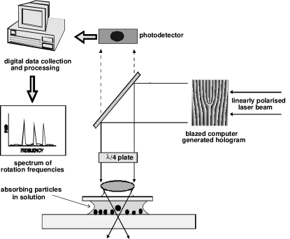
The experimental set-up we used for studies of trapping of absorbing particles is similar to the one described in the earlier part of this paper with only a few modifications: a Gaussian TEM00 beam from a 17 mW He–Ne laser is passed through a computer generated phase hologram, which produces a Gauss–Laguerre LG03 mode in the far field. This plane polarised, helical doughnut beam is then introduced in the usual way into the microscope (see Figure 3).
The trapping of absorbing particles was performed using irregular black ceramic particles and CuO particles dispersed in kerosene. We have also trapped slightly absorbing latex spheres which were in clumps so that their rotation could be more easily observed.
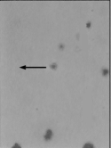
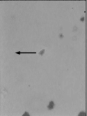
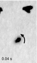
We found that most efficient trapping was achieved with the particles slightly above the focal plane of the doughnut beam. A variety of experiments was performed. Firstly, trapping and rotation could be observed using a CCD camera fitted to the microscope. In this set of studies the absorbing particles were trapped when the hologram of charge 3 was placed in the beam. A particle was trapped and observed to rotate. The rotation could be observed for a long period of time. Subsequently the hologram was moved sideways so that the particle was illuminated by a Gaussian beam and stopped rotating. As the hologram used here is blazed the sign of the doughnut can be simply reversed by turning the hologram around. In principle, on the reversal of the hologram, the particle should rotate in the opposite direction. However, in the process of turning the hologram, the particle is no longer trapped and so on the reversal of the hologram, it is not certain that the retrapped particle is the same as before. It is, however, certain that on the reversal of the hologram, all of the trapped particles rotate in the opposite direction. Another method of reversing the helicity of the doughnut beam is to introduce a Dove prism into the beam path between the hologram and the microscope. As the beam undergoes one reflection in the prism, its helicity is reversed and the prism can be adjusted in such a way so that the beam will be undeviated. With the Dove prism in the beam path, we now trap the particle, detect its direction of rotation and then quickly remove the Dove prism so that the same particle is still trapped. The direction of rotation is reversed ref19 ; ref47 . The sequence of events is recorded and reproduced frame by frame (see Figure 4).
 |
 |
 |
 |
 |
 |
 |
 |
 |
 |
 |
 |
 |
 |
 |
 |
 |
 |
 |
 |
This method of detection has serious limitations, as particles move out of clear focus when they are trapped and so their images are not well defined on video. In the second set of experiments the experimental set-up was refined in two ways. Firstly, a quarter-wave plate was introduced into the beam path directly before the microscope objective (NA) which, as before, focused the doughnut beam to a waist size of approximately 2 µm in diameter. The purpose of this experiment was to allow a precise measurement of the rotation speed and also to study the influence of the added circular polarisation of the beam by which the theoretical prediction of the total transfer of angular momentum could be verified.
A second refinement was made to allow for precise measurement of the rotation frequency. The rotation was this time measured using a photodetector positioned off centre to detect a portion of the light reflected from the rotating particle. The particles are irregularly shaped and the protruding parts of the particles reflect a “flash” of light onto the displaced detector. The signal of intensity fluctuations over time obtained from the photodetector is Fourier transformed yielding the rotation frequency of the particle. The modified experimental set-up for the above experiments is shown in Figure 3.
The sequence of the experiment is as follows. The LG03 beam enters the microscope. It passes through a plate and its focus is adjusted to be slightly below the focal point of the microscope. The polarisation state is checked after the objective lens by an analyser and the power of the beam is monitored for each position of the plate (left and right-circularly polarised light and linearly polarised light). It was established that the power output varied less than 1% between different polarisations. Care was taken to position the plate in such a way as not to cause any deflection of the beam when the plate was rotated. The sample of absorbing CuO particles of sizes up to 20 µm in kerosene was placed between a glass microscope slide and coverslip. A particle was trapped into the linearly polarised helical doughnut and the plate rotated firstly to right circular polarisation, back to linear and then to left circular polarisation. The signal was sampled at 20 Hz for a period of 100 s. The sequence was repeated and the reflected light monitored on the photodetector. An example of the spectrum resulting from this experiment is shown in Figure 5. It can be seen from this figure that rotation frequency increases when the helicity of the electric field vector has the same direction as the helicity of the Poynting vector and decreases when these directions are opposite to each other.
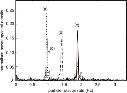
Using an LG03 doughnut the theoretical prediction is that the frequencies should scale as 2:3:4 when going from opposite helicity Poynting vector and spin to linearly polarised helical wave front through to the same helicities. This was verified experimentally (see Figure 5).
Recently a somewhat similar experiment has been performed by Simpson et al. ref23 using a charge one Gauss–Laguerre laser mode produced by operating a laser in a Hermite–Gaussian mode and converting the output into the corresponding Gauss–Laguerre mode using a cylindrical lens mode converter. A quarter-wave plate was used to change polarisation. The authors showed that spin angular momentum of per photon associated with circularly polarised light can add to, or subtract from, the orbital angular momentum and observed the mutual cancellation of the spin and orbital angular momentum. Their results confirm the results obtained by our group and show that the LG01 mode of charge 1 has a well-defined orbital angular momentum corresponding to per photon.
In our most recent experiments we have shown that an absorbing particle can in fact be trapped by a Gaussian beam. Two-dimensional trapping can be achieved before the waist of a tightly focused Gaussian beam, where the spot size is rapidly changing, against a surface such as a microscope slide, using radiation pressure. The particle was first trapped using linearly polarised Gaussian beam and subsequently by turning a plate a circularly polarised Gaussian beam was used to trap the particle resulting in a rotation of this particle. When the plate was rotated to produce circularly polarised light of the opposite sense, the particle reversed the direction of rotation. Successive frames from a video demonstrating trapping are shown in Figure 6.
| (a) | 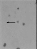 |
 |
 |
|---|---|---|---|
| (b) | 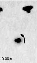 |
 |
 |
III Theory of trapping of absorbing particles
The physical basis of the trapping of absorbing particles can be investigated in terms of the interaction between radiation and matter. For highly absorbing particles, effects such as induced polarisation within the particle, refraction and Doppler shifts which are important for transparent particles and atoms can be neglected. The properties of the trap depend mainly on the properties of the trapping beam, which will be assumed to be paraxial. While a non-paraxial beam is necessary for laser trapping, the use of the paraxial approximation does not seem to introduce excessive error. Errors due to aberration within the optical system are expected to be greater.
The theory will be developed in terms of the two most common types of beams used for trapping particles, namely TEM00 Gaussian beams [denoted (G)] and LGpl Laguerre–Gaussian “doughnut” beams [denoted (LG)] described by a radial mode index and an azimuthal mode index .
III.1 The transfer of linear momentum and orbital angular momentum
We begin with consideration of the transfer of linear momentum to an absorbing infinitesimal element. This microscopic behaviour can then be extended to the particle as a whole. In the course of this, it can be seen that the transfer of orbital angular momentum from a helical beam to a particle is a simple radiation pressure process involving the transfer of linear momentum to different portions of the particle. Due to the spatial structure of the helical beam, this results in a transfer of angular momentum.
III.2 Microscopic transfer of momentum
Due to the cylindrical symmetry of the beam, it is convenient to use a cylindrical coordinate system, with radial, azimuthal and axial coordinates , , and , and corresponding unit vectors , , and . The linear momentum flux of a laser beam is given by the time-averaged Poynting vector (in cylindrical coordinates) ref48 :
| (3) |
| (4) |
where is the Rayleigh range, is the wavenumber of the beam, and is the amplitude of the beam, given by ref49
| (5) |
| (6) | |||||
where is the beam power, is the beam width, is the generalised Laguerre polynomial, is the speed of light and is the permittivity. The Rayleigh range and the beam width are related to each other and the beam waist spot size by:
| (7) |
| (8) |
| (9) |
For most cases of interest involving doughnut beams, the radial mode index and the Laguerre polynomial . If an area element is highly absorbing, the rate of momentum transfer to it will be given by the Poynting vector :
| (10) |
The transfer of momentum from the beam to an absorbing particle is therefore straightforward compared to other cases, such as transparent particles and atoms. For transparent particles, refraction and induced polarisation must be taken into account. For an atom, the frequency dependence of the absorption and spontaneous emission must be considered, while for an absorbing particle, the absorption can be assumed to be independent of frequency, and inter-atomic collision rates within the particle can be assumed to be high enough to cause de-excitation without re-emission.
III.3 Macroscopic effects
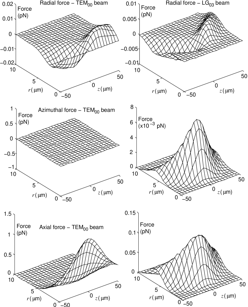
As particles typically are sufficiently large that the Poynting vector of the laser beam is not constant over their absorbing surfaces, it is necessary to integrate the Poynting vector over the surface. This requires knowledge of the geometry of the particle and the beam. This calculation can be readily performed numerically by dividing the particle into a number of small area elements dA over which the Poynting vector is approximately constant, and integrating equation (10). Where the product , the particle will not be illuminated, so such regions can be neglected. A useful and simple approximation is to simply represent the particle as a disk with the same cross-section (essentially applying the paraxial approximation to the illumination of the particle). The resultant force on a particle is shown in Figure 7.
Equilibrium points in these force fields exist only where the force is zero, and a particle can be trapped only at a stable equilibrium point. Thus, it can be readily seen that a particle cannot be axially trapped without an external force (such as gravity, viscous drag due to convection, or a reaction force due to the particle resting on the bottom of the trapping cell) acting on it. The particle can be trapped radially in the portion of the beam which is converging towards the beam waist. The particle cannot be trapped after the beam waist, as the convergence of the beam required for trapping no longer exists. The absorbing particle trap can therefore be considered to be a two-dimensional trap. Also, it should be noted that in the case of Laguerre–Gaussian beams, angular momentum is transferred to the particle as a whole, although microscopically only linear momentum is seen to be present.
The relative efficiencies of trapping absorbing particles using Gaussian beams and doughnut beams can be measured in terms of the ratio of the radial force to the axial force. As can be seen from Figure 8, the doughnut beam trap has smaller axial forces for trapped particles.

As the force acting on a particle at any position within the beam can be calculated, the overall properties of the trap, such as the trapping force, or the motion of trapped particles can be determined. If particles are confined to a two-dimensional plane in which they are radially trapped, particles trapped in Gaussian beams are pushed into the centre of the trap, while particles trapped in Laguerre–Gaussian beams also tend to orbit about the beam axis due to the azimuthal component of the force. This orbital motion can lead to instability in the trap, as a particle undergoing such motion will only remain within the trap if the radial force can provide a centripetal force sufficient to force the path to become circular. If the viscosity of the surrounding medium is too low, the terminal orbit speed will be high enough so that the radial force will be unable to provide the necessary centripetal acceleration and the particle will escape from the trap. Particles trapped in fluids such as water or kerosene, however, have very low terminal speeds and can be trapped.
IV Transfer of Spin Angular Momentum
As seen above, any orbital angular momentum present in a helical laser beam (for example, a Laguerre–Gaussian beam) is transferred to a particle by the same mechanisms as linear momentum. All laser beams, however, can carry angular momentum if the beam is circularly polarised, with each photon having angular momentum of magnitude . The rate of absorption of angular momentum by a small section of the particle is given in terms of the Poynting vector and the wavenumber by
| (11) |
where for left- and right-circular polarisation and for plane polarisation.
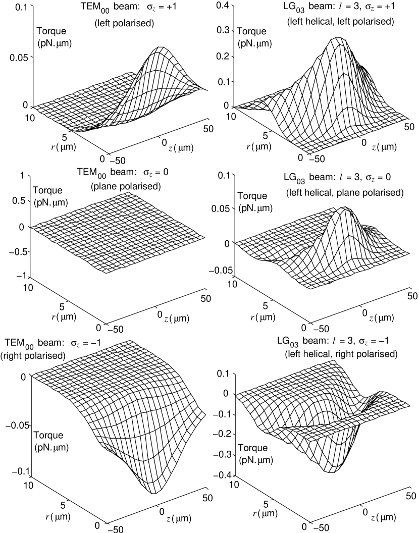
The total torque on the particle due to polarisation can then be found by integrating equation (11) over the absorbing surface of the particle (see Figure 9). The rotational behaviour of particles trapped in a Gaussian beam is straightforward. However, that of a particle illuminated by a Laguerre–Gaussian beam is more complex, due to the presence of the orbital angular momentum. In practice a particle is trapped on the beam axis. The total torque due to polarisation on a particle of radius trapped on the beam axis is given by
| (12) |
| (13) |
where is the angular frequency of the light. The total torque can be found by combining this with the torque due to the orbital angular momentum carried by the helicity of the beam
| (14) |
| (15) |
The angular velocity in a viscous medium will depend on the drag torque, which for a smooth spherical particle of radius in a medium of viscosity is given by ref50
| (16) |
and the optical torque. The resultant spin rates for particles trapped on the beam axis are
| (17) |
| (18) | |||||

The rotation rate for particles trapped in a Gaussian beam rises as the particles become small. When the spin rate becomes large, equation (16) will cease to be applicable. For particles trapped in the doughnut beam, the rotation rate is maximum for a particle large enough to absorb most of the beam, but small enough to keep the drag surface area small.
In a typical experiment, ceramic particles with radii of about 2 µm, suspended in kerosene, were trapped in a beam of 4 mW power and a width of 1.75 µm. Rotation rates of 1–2 Hz were observed (see Figure 5), consistent with the predictions of equation (18) and Figure 10.
V Absorption of Energy
The energy density in a focussed beam of even modest power can be very large. For example, in a 1 mW beam focussed to a 1 µm waist, the irradiance will exceed W/m2. The transparent objects conventionally trapped by optical tweezers evidently absorb very little, partly because they are very thin, and they are surrounded by a conducting medium so experience only modest rises in temperature. Indeed, it has been shown that bacteria will survive and even reproduce while trapped.
The situation for strongly absorbing particles is very different. A typical 1 µm radius particle absorbing 1 mW will, in the absence of any losses, experience a temperature rise of order K/s. Clearly, the temperature of a trapped particle will rise rapidly and it is necessary to consider what losses will limit the rise.
Since the surface area is small, even neglecting local absorption in the surrounding medium, the amount of heat which can be radiated is limited. Stefan’s Law shows that a particle of 1 µm radius needs to have a surface temperature in excess of 1000 K before the power radiated exceeds 1 µW. The small surface area also severely limits the rate at which heat can be exchanged with the surrounding fluid.
If we consider a spherical particle in equilibrium losing the heat absorbed from the beam by isotropic conduction into a surrounding medium of thermal conductivity , the radial variation of the temperature in the surrounding medium can easily be shown to be given by
| (19) |
where is the total power absorbed by the particle from the beam and is the ambient temperature. The absorbed power for a particle with absorption coefficient trapped on the beam axis of a TEM00 Gaussian or LG0l Laguerre-Gaussian beam of power is given by
| (20) |
| (21) |
Calculated equilibrium temperatures reached by typical particles trapped in a 1 mW beam are shown in Figure 11.

Quite high temperatures are predicted, especially for particle sizes on the order of the spot size.
Convection is another possible means of heat loss. The importance of convection can be found in terms of the mean Nusselt number , which, at low flow rates, is given in terms of the Prandtl number (the ratio between the momentum and thermal diffusivities) and the Grashof number (the ratio between buoyant and viscous forces) by ref51
| (22) |
The Grashof number is given by ref52
| (23) |
and the Prandtl number by
| (24) |
where is the specific heat of the fluid, is the dynamic viscosity and is the kinematic viscosity.
For a temperature difference of 100 K and an ambient temperature of 300 K, and a particle diameter of µm (at which size high temperatures are reached for a typical beam), for water and for kerosene, values which are very close to for pure conduction. The convective contribution to the cooling is therefore negligible.
We are therefore driven to the conclusion that even in the presence of a liquid medium, an absorbing particle will experience a large rise in temperature, probably limited by thermal conduction. Note that due to the dependence of the temperature rise in that case, the volume where elevated temperatures will be found is quite small which means in turn that the thermal relaxation time will be short, so that the temperature rises will be difficult to measure.
However, we do have evidence of such large temperature rises. In experiments where we trapped small particles of photocopy toner, we observed that initially jagged fragments almost instantly became smooth when irradiated by a beam with a power of a few mW. According to the manufacturer’s specifications, the fusing point of the toner is 185°C. These results are at first rather surprising as it might have been expected that boiling of the liquid would enhance cooling or disrupt the trapping process. Sometimes, with beam powers well in excess of that required to melt toner, a bubble is generated but it is not clear if this is vapour or merely absorbed gases being evolved from the particle. The boiling process in general is a somewhat mysterious one and it is widely accepted that bubble formation requires some seed to overcome surface tension forces which scale inversely as the radius. Therefore it cannot be taken for granted that normally observed behaviour will scale to very small dimensions. If so, further study of superheated particles may help shed new light on the fundamentals of the boiling process.
VI Interaction with the Medium
Interactions with the surrounding transparent medium include the heating of the medium through conduction from the absorbing particle, and the generation of fluid motions through stirring and convection currents.
Temperature changes in the medium will be localised to within 100 µm of the particle but could affect properties such as the refractive index and viscosity. It is also possible that thermophoretic effects may occur in the strong temperature gradients formed.
Stirring and convection effects have both been observed when CuO particles were trapped, using a doughnut beam, in water to which a little detergent had been added. This greatly reduced the tendency of particles to stick to the slide and generally freed up their motion so that Brownian motion was more evident. When a particle was trapped, others in its vicinity began to move toward it, presumably as a result of a convection currents, and began to circle around the trapped particle in the same direction as its rotation, presumably carried around by a flow generated by the rotation of the trapped particle. The fluid velocities of the order of 10 µm/s are too small to significantly affect heat transport.
VII Conclusion
It has been shown that the converging section of a focussed laser beam can radially trap absorbing particles against a supporting substrate using a Gaussian or doughnut beam. Doughnut beams with phase singularities carry angular momentum which is also transferred to the trapped particle causing it to rotate. Angular momentum resulting from circular polarisation of the light can also be transferred. Energy absorbed from the beam can lead to rapid heating and high equilibrium temperatures, even well in excess of the normal boiling point of the surrounding medium.
References
- (1) A. Ashkin Physical Review Letters 24, 156 (1970)
- (2) A. Ashkin Science 220, 4474 (1980)
- (3) A. Ashkin, J.M. Dziedzic, J.E. Bjorkholm and S. Chu Optics Letters 11, 288 (1986)
- (4) G. Roosen and C. Imbert Optics Communications 26, 432 (1978)
- (5) W.H. Wright, G.J. Sonek, Y. Tadir and M.W. Berns IEEE Journal of Quantum Electronics 26, 2148 (1990)
- (6) J.G. Mitchell, R. Weller, M. Beconi, J. Sell and J. Holland Microbial Ecology 25, 113 (1993)
- (7) R. Huber, S. Burggraf, T. Mayer, S.M. Barns, P. Rossnagel and K.O. Stetter Nature 376, 57 (1995)
- (8) K. Schütze Nature 368, 667 (1994)
- (9) K. Schütze, A. Clementsengewald and A. Ashkin Fertility and Sterility 61, 783 (1994)
- (10) Y. Liu, G.J. Sonek, M.W. Berns, K. Konig and B.J. Tromberg Optics Letters 20, 21 (1995)
- (11) S.M. Block, D.F. Blair and H.C. Berg Nature 338, 514 (1989)
- (12) T. Nishizaka, H. Miyata, H. Yoshikawa, S. Ishiwata and K. Kinosita Jr Biophysical Journal 68, 75s (1995)
- (13) T.T. Perkins, D.E. Smith and S. Chu Science 264, 819 (1994)
- (14) Y. Liy, D.K. Cheng, G.J. Sonek, M.W. Berns, C.F. Chapman and B.J. Tromberg Biophysical Journal 68, 2137 (1995)
- (15) H. Liang, K.T. Vu, T.C. Trang, D. Shin, S. Kimel and M.W. Berns Biophysical Journal 70, 1529 (1996)
- (16) K. K nig, H. Liang, M.W. Berns and B.J. Tromberg Nature 377, 20 (1995)
- (17) K. Svoboda and S.M. Block Optics Letters 19, 930 (1994)
- (18) S. Sato, Y. Harada and Y. Waseda Optics Letters 19, 1807 (1994)
- (19) M.E.J. Friese, H.He, N.R. Heckenberg and H. Rubinsztein-Dunlop “Transfer of angular momentum to absorbing particles from a laser beam with a phase singularity” pg 190 in N.B. Abraham and Y.I. Kanin (eds) Laser Optics ’95: Nonlinear Dynamics in Lasers Proc SPIE 2792 190–195(1996)
- (20) M.E.J. Friese, J. Enger, H. Rubinsztein-Dunlop and N.R. Heckenberg Physical Review A 54, 1593-1596 (1996)
- (21) H. He, M.E.J. Friese, N.R. Heckenberg and H. Rubinsztein-Dunlop Physical Review Letters 75, 826 (1995)
- (22) H. He, N.R. Heckenberg and H. Rubinsztein-Dunlop Journal of Modern Optics 42, 217 (1995)
- (23) N.B. Simpson, K. Dholakia, L. Allen and M.J. Padgett Optics Letters 22, 52 (1997)
- (24) T. Sugiura, S. Kawata and S. Minami Journal of the Spectroscopical Society of Japan 39, 342 (1990)
- (25) A. Ashkin, J.M. Dziedzic and T. Yamane Nature 330, 769 (1987)
- (26) S. Sato, M. Ohyumi, H. Shibate and H. Inabe Optics Letters 16, 282 (1991)
- (27) L. Malmqvist and H.M. Hertz Optics Communications 94, 19 (1992)
- (28) I.A. Vorobjev, H. Liang, W.H. Wright and M.W. Berns Biophysical Journal 64, 533 (1993)
- (29) C. D’Helon, E.W. Dearden, H. Rubinsztein-Dunlop and N.R. Heckenberg Journal of Modern Optics 41, 595 (1993)
- (30) S. Sato and H. Inabe Optics Letters 19, 927 (1994)
- (31) T.N. Buican, M.J. Smyth, H.A. Crissman, G.C. Salzman, C.C. Stewart and J.C. Martin Applied Optics 26, 5311 (1987)
- (32) L.P. Ghislain, N.A. Switz and W.W. Webb Review of Scientific Instruments 65, 2762 (1994)
- (33) H. Liang, K.T. Vu, P. Krishnan, T.C. Trang, D. Shin, S. Kimel and M.W. Berns Biophysical Journal 70, 1529 (1996)
- (34) E. Fällman and O. Axner Applied Optics 36, 2107 (1996)
- (35) M.W. Berns, W.H. Wright and R.W. Steubing International Reviews of Cytology 129, 1 (1991)
- (36) S.M. Block Nature 360, 493 (1992)
- (37) S.C. Kuo and M.P. Scheetz Trends in Cell Biology 2, 116 (1992)
- (38) G. Weber and K.O. Greulich International Reviews of Cytology 133, 1 (1992)
- (39) A. Ashkin, K. Schütze, J.M. Dziedzic, U. Euteneuer and M. Schliwe Nature 348, 346 (1990)
- (40) S.M. Block, D.F. Blair and H.C. Berg Cytometry 12, 492 (1990)
- (41) S.C. Kuo and M.P. Sheetz Science 260, 232 (1993)
- (42) L.P. Ghislain and W.W. Webb Optics Letters 18, 1678 (1993)
- (43) K. Svoboda, C.F. Schmidt, B.J. Schnapp and S.M. Block Nature 365, 721 (1993)
- (44) M.E.J. Friese, H. Rubinsztein-Dunlop, N.R. Heckenberg and E.W. Dearden Applied Optics 35, 7112 (1996)
- (45) K. Sasaki, M. Koshioka, H. Misawa and N. Kitamura Applied Physics Letters 60, 807 (1992)
- (46) S.M. Barnett and L. Allen Optical Communications 110, 670 (1994)
- (47) http://www.physics.uq.edu.au/lp/tweezers/
- (48) M.J. Padgett and L. Allen Optics Communications 121, 36 (1995)
- (49) M.W. Beijersbergen, L. Allen, H.E.L.O van der Veen and J.P. Woerdman Optics Communications 96, 123 (1993)
- (50) L.D. Landau and E.M. Lifshitz Fluid Mechanics 2nd ed., Pergamon Press (1987)
- (51) R.C. Armstrong Heat Exchanger Design Handbook Vol 2 Hemisphere Publishing Corporation (1989)
- (52) F.P Incropera and D.P. De Witt Fundamentals of Heat and Mass Transfer 4th ed., Wiley (1996)