Optical application and measurement of torque on microparticles
of isotropic nonabsorbing material
Abstract
Preprint of:
Alexis I. Bishop, Timo A. Nieminen, Norman R. Heckenberg, and Halina Rubinsztein-Dunlop,
“Optical application and measurement of torque on microparticles of isotropic nonabsorbing material”,
Physical Review A 68, 033802 (2003)
We show how it is possible to controllably rotate or align microscopic particles of isotropic nonabsorbing material in a TEM00 Gaussian beam trap, with simultaneous measurement of the applied torque using purely optical means. This is a simple and general method of rotation, requiring only that the particle is elongated along one direction. Thus, this method can be used to rotate or align a wide range of naturally occurring particles. The ability to measure the applied torque enables the use of this method as a quantitative tool—the rotational equivalent of optical tweezers based force measurement. As well as being of particular value for the rotation of biological specimens, this method is also suitable for the development of optically-driven micromachines.
pacs:
42.62.Be,42.62.Eh,42.25.Fx,42.25.JaI Introduction
Optical forces have been widely used to trap and manipulate microscopic particles for many years Ashkin et al. (1986), with the single beam gradient trap, also called optical tweezers, being the most common type. Optical tweezers are used for a wide variety of applications, including the trapping and manipulation of biological specimens such as living cells and organelles, the study of single molecules such as DNA, and the measurement of piconewton forces and nanometer displacements Ashkin (2000). The optical forces acting to trap the microparticle result from the transfer of momentum from the trapping beam to the particle by absorption or scattering. Since light can carry angular momentum as well as (linear) momentum, transfer of angular momentum can be used to produce optical torque. This introduces the possibility of true three-dimensional manipulation within laser traps—the ability to controllably rotate or orient optically trapped microscopic particles is a major advance in the manipulation possible within a laser trap. This is of interest not only for simple manipulation, but also for the use of rotation as a tool to probe microscopic properties of fluids or biological specimens Nieminen et al. (2001a), and the possibility of developing optically powered and controlled micromachines Friese et al. (2001); Galajda and Ormos (2001).
A variety of methods of optical rotation have already been proposed and tested. However, most methods either degrade the performance of the trap, are overly complex, or are of limited applicability since they require special types of particles. We report the rotation of elongated particles composed of isotropic nonabsorbing material in a TEM00 Gaussian beam trap, using a plane polarised beam to align the particle with the plane of polarization, a rotating plane polarized beam to rotate the particle at a controlled rate, or a circularly polarised beam to rotate the particle with constant torque. Alignment to, and rotation by, plane polarized beams has recently been reported by a number of groups Bayoudh (1999); Bayoudh et al. (in press); Bonin et al. (2002); Galajda and Ormos (2003). Our observation of rotation in circularly polarized beams appears to be the first report of this effect. Because this method of rotation places only weak restrictions on the type of particle—it must be elongated along one or more directions—it is applicable to a wide range of naturally occurring particles, including biological specimens. The use of a TEM00 Gaussian beam allows strong three-dimensional trapping to be achieved.
We computationally model our experiments, using the T-matrix method Mishchenko et al. (2000); Waterman (1971); Mishchenko (1991); Nieminen et al. (2003a) to calculate the scattering of the trapping beam by the particle, and hence, the optical force and torque. The T-matrix method uses a full vector wave rigorous solution of the Maxwell equations. Our theoretical results unambiguously confirm our interpretation of our qualitative and quantitative experimental results.
We also show that it is possible to measure the optical torque applied to the particle, using purely optical means. Apart from being of interest for monitoring the torque, it enables the use of this method as a quantitative tool—the rotational equivalent of optical tweezers based force measurement. This does not depend on any knowledge of the physical properties of the particle or the medium in the vicinity of the particle, and can be used as a quantitative probe to determine physical properties such as viscosity or elasticity.
II Optical rotation
A laser beam carries angular momentum in two distinct forms: spin angular momentum, associated with the polarization of the beam, and orbital angular momentum, associated with the spatial structure of the beam Padgett and Allen (2000). The spin angular momentum varies from to per photon, depending on the degree of circular polarization, while the orbital angular momentum is essentially arbitrary, depending on the geometry and spatial and phase structure of the beam. Well-defined laser beam modes typically carry an integer times per photon about the beam axis.
Torque results from the scattering (including absorption) of light if either the orbital angular momentum or the spin angular momentum is altered. This can be achieved by absorption of energy from a beam carrying either spin or orbital angular momentum, or both Simpson et al. (1997); Friese et al. (1996), or by change of spin angular momentum by birefringent particles Friese et al. (1998); Higurashi et al. (1999), by the use of specially fabricated particles which function as optical “windmills” Galajda and Ormos (2001); Luo et al. (2000); Ukita and Kanehira (2002), or by the use of asymmetric trapping beams Paterson et al. (2001); Sato et al. (1991); Santamato et al. (2002); O’Neil and Padgett (2002).
Methods using absorption have limited applicability due to heating as a result of absorption of energy, and methods depending on special types of particles can only be used if suitable particles (birefringent or fabricated) are avaliable. (We note in passing that the optical “windmill” particles mentioned above are essentially microscopic versions of the spiral phase holograms that can be used to produce vortex beams Heckenberg et al. (1992).)
Shaped beam methods Paterson et al. (2001); Sato et al. (1991); Santamato et al. (2002); O’Neil and Padgett (2002) offer much greater flexibility, but require more complicated trapping apparatus, and can suffer from reduced axial trapping due to spreading of the focal spot. Since these methods depend on the spatial structure of the focal spot of the trapping beam, the torque experienced by the particle is due to the generation of orbital angular momentum—this has important implications for the optical measurement of the torque.
In principle, the applied torque can be measured optically—the optical torque results from the change in the spin or orbital angular momentum of the beam by scattering. If the angular momentum carried by the incident light is known (or measured), measurement of the angular momentum of the scattered light gives the optical torque directly in absolute terms without the need for any calibration. Since the spin angular momentum depends on the polarisation state of the light, which can be readily and accurately measured, the spin component of optical torque can be found simply Nieminen et al. (2001a). While it is possible in principle to measure the orbital angular momentum of light, no simple and accurate method of doing so for an arbitrary optical field has yet been reported; the orbital component of optical torque must presently be regarded as unmeasurable without a great deal of effort.
III A simple and general method for optical rotation
Previous methods for optical rotation are limited in their applicability. It would be especially useful to be able to rotate or align the largest possible range of naturally occurring particles, including biological specimens (which precludes the use of absorption due to the risk of thermal damage), while still being able to trap them three-dimensionally. Maintaining three-dimensional trapping excludes methods that require spreading of the focal spot. Such a method would be most useful if it can be simply added to an existing optical tweezers setup.
Elongated dielectric particles tend to align with static electric fields since elongated (or flattened) particles have different dielectric polarisabilities along their long and short axes Jones (1945)—in effect, the particles act as if they are birefringent. Alignment in optical fields due to this form birefringence Born and Wolf (1997), resulting from the overall shape of the particle and not its microscopic structure, has already been used for the production of artificial non-linear optical media Kralik et al. (1995), remote sensing of aerosols Palmer (1980), and the alignment of molecules Sakai et al. (1999)—the smallest possible elongated particles. This method has recently been shown to be feasible for the rotation of optically trapped microparticles Bayoudh (1999); Bayoudh et al. (in press); Bonin et al. (2002); Galajda and Ormos (2003). Thus, it appears that the simplest scheme for the rotation and alignment of microscopic particles is to use a plane-polarised Gaussian TEM00 beam. The only requirement is that the particle be non-spherical—this is a technique of broad generality.
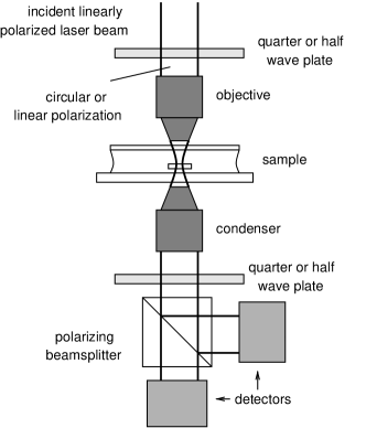
The method described above is simple to implement—we insert either a half-wave waveplate to control the direction of the plane of polarization of the trapping beam, or a quarter-wave waveplate to produce a circularly polarized trapping beam (figure 1). The laser beam is initially plane polarized, and the optics in the beam path are arranged so as to preserve this polarization, by ensuring that the beam is purely or polarized at all mirrors, until the waveplate is reached. Since this is not possible for a beam plane polarized in an arbitrary plane, or circularly polarized, the waveplate is best placed in the beam path immediately in front of the objective. As the half-wave waveplate is rotated through an angle, the plane of polarization of the trapping beam rotates through twice that angle. Otherwise, the optical tweezers apparatus we used was a standard single-beam trap using a 1064 nm beam focussed by an oil-immersion 100 objective of numerical aperture 1.3. Beam powers of 10–100 mW were used. The beam waist radius was typically about 0.8 m.
Some of the non-spherical particles we manipulated were glass rods (refractive index of 1.51 at 1064 nm), with radii from 0.1–2 m and lengths from 1 m to over 10 m, dispersed in water (refractive index of 1.35 at 1064 nm). These glass rods align along the beam axis when three-dimensionally trapped. However, if the rods are trapped very close to the microscope slide, with insufficient space in which to stand upright, they align with the plane of polarization of the trapping beam (figure 2). It has already been shown that three-dimensionally trapped oblate particles will first align with a long axis along the beam axis, and will then rotate so that the remaining long axis aligns with the plane of polarization Bayoudh (1999); Bayoudh et al. (in press); Galajda and Ormos (2003). We will show in the next section that this behaviour agrees with theoretical models.
| (a) |


|
|---|---|


|
|
| (b) |


|


|
|
| (c) |


|


|
In order to be able to produce steady rotation using a plane-polarized beam, the half-wave waveplate controlling the direction of the plane of polarization was placed in a rotatable mount, and rotated by a friction belt driven by a stepper motor. Rotation rates of up to 20 Hz were achieved, with the maximum speed limited by the maximum rotation rate at which the waveplate could be driven.
As we noted earlier, the torque that acts to align the rods with the plane of polarization results from the transfer of angular momentum from the beam to the rod. We measured the polarization state of the transmitted light (figure 1) and observed the presence of partial circular polarization. We used the measurements of the polarization state of the transmitted light to determine the spin component of the optical torque. Measurements of this type can be made for both rotating and stationary particles. We discuss these results fully in the following sections.
Since the elongated rods are effectively birefringent (form birefringence), they should not only change the polarization state of a linearly polarized incident beam, but also that of a circularly polarized beam. Therefore, a circularly polarized beam would be expected to produce a torque that is independent of the orientation of the particle perpendicular to the beam axis; it should be possible to use this to rotate the particle at a constant rate.
We produced a circularly polarized trapping beam by replacing the half-wave plate before the objective by a quarter-wave plate. We were then able to rotate the glass rods in the circularly polarized beam, achieving rotation rates of over 10 Hz. We confirmed that the physical mechanism described above was responsible for the rotation by measuring the polarization state of the transmitted light. We also observed that the direction of rotation could be reversed by changing the handedness of the circular polarization of the beam. The torque generated by a circularly polarized beam is lower than that produced by a plane-polarized beam, but the angle-independence of the torque might make the method attractive for some applications. This appears to be the first report of this effect; the torque is small, and has not been previously noted.
IV Theoretical modelling
Optical forces and torque result from the conservation of momentum and angular momentum when a particle scatters light, changing the momentum or angular momentum. Therefore, if the scattering of the incident beam by the glass rods can be calculated, the optical force and torque acting on them can be calculated Nieminen et al. (2001b, c); Farsund and Felderhof (1996). The glass rods that we wish to model are simultaneously too large for the Rayleigh (ie small particle) approximation to be valid, and too small for the geometric optics approximation to be valid. Therefore, a full electromagnetic wave scattering calculation is needed. We calculate the scattered fields using the T-matrix method Mishchenko et al. (2000); Waterman (1971); Mishchenko (1991); Nieminen et al. (2003a), in which the incident and scattered fields are expanded in terms of vector spherical wavefunctions (VSWFs), which are also known as the electric and magnetic multipole fields.
The T-matrix method is well-suited for optical force and torque calculations since the T-matrix for a given particle only needs to be calculated once Nieminen et al. (2001b, c) for a particular wavelength, and can then be used for any incident beam of that wavelength. The mathematical formulation of the T-matrix method is also physically enlightening since the VSWFs are simultaneous eigenfunctions of the total angular momentum operator, with eigenvalues , and the -component of angular momentum operator, with eigenvalues .
In our T-matrix calculations, the incoming and outgoing fields are expanded in terms of incoming and outgoing VSWFs:
| (1) | |||||
| (2) |
where the VSWFs are
| (3) | |||||
where are spherical Hankel functions of the first and second kind, are normalization constants, and , , and are the vector spherical harmonics Mishchenko et al. (2000); Waterman (1971); Mishchenko (1991); Jackson (1999), and are normalized scalar spherical harmonics. The usual polar spherical coordinates are used, where is the co-latitude measured from the axis, and is the azimuth, measured from the axis towards the axis. We note that our division of the fields into a purely incoming incident field and an outgoing scattered field is unusual; it is much more common to use an incident–scattered field formulation Nieminen et al. (2003a). The two different formulations are essentially equivalent; our choice simplifies the expressions for optical force and torque. In practice, the field expansions and the T-matrix must be terminated at some finite chosen so that the numerical results converge with sufficient accuracy Nieminen et al. (2003a, b); Brock (2001).
The expansion coefficients of the incoming field are calculated using far-field point-matching Nieminen et al. (2003b), and the T-matrix is calculated by using a row-by-row point-matching method, exploiting symmetry of the particle when possible Nieminen et al. (2003a). The expansion coefficients of the outgoing (ie scattered) field are found from the expansion coefficients of the incoming field using the T-matrix:
| (5) |
where and are vectors formed from the expansion coefficients of the incident wave ( and ) and the scattered wave ( and ).
The torque efficiency, or normalized torque, about the -axis acting on a rod is
| (6) | |||||
in units of per photon, where
| (7) |
is proportional to the incident power (omitting a unit conversion factor which will depend on whether SI, Gaussian, or other units are used). This torque includes contributions from both spin and orbital components; the normalized spin torque about the -axis is given by Crichton and Marston (2000)
| (8) | |||||
The remainder of the torque is the orbital contribution. The axial trapping efficiency is Crichton and Marston (2000)
| (9) | |||||
in units of per photon.
We use the same formulae to calculate the and components of the optical force and torque, using rotations of the coordinate system Choi et al. (1999). It is also possible to directly calucate the and components using similar, but more complicated, formulae Farsund and Felderhof (1996).
We note that the T-matrix is diagonal with respect to if the scatterer is rotationally symmetric about the axis Mishchenko et al. (2000); Mishchenko (1991); Nieminen et al. (2003a). Therefore, it can be seen from (6) that, in the absence of absorption, no torque can be exerted on a particle that is rotationally symmetric about the axis. A particle elongated along the axis will couple incoming and outgoing VSWFs with due to the twofold rotational symmetry—this angular momentum coupling allows torque to be generated. If the incident beam is plane polarized along the axis, but otherwise rotationally symmetric, the expansion coefficients are of the form Nieminen et al. (2003b); Gouesbet (1996) and . In this case, due to the mirror symmetry about the – plane, there can be no torque—the coupling is such that and . If the plane of polarization of the beam is rotated by about the axis, the expansion coefficients become and . This change in complex phase of the coefficients allows and to result, with a consequent sinusoidal dependence of the torque on the angle between the particle symmetry plane and the plane of polarization.
If the incident beam is left-circularly polarized, then only and are non-zero. Coupling to the VSWFs results in a torque; since the phase shift due to rotation of the beam will affect all incoming (and therefore outgoing) coefficients equally, the torque is independent of the orientation of the particle in the – plane.
V Quantitative results
Our optical measurements of the spin contribution to the torque, along with the theoretical methods described in the previous section allow us to make a direct comparison of our experiment with theory. Our theoretical calculations use direct measurements of the beam focal spot size and the measured sizes of the glass rods; all required quantities are known, with no need to match theoretical curves to observations by curve-fitting to determine remaining free parameters.
Our general method of optical torque measurement has been described previously Nieminen et al. (2001a). For the case of a plane polarized incident beam, the incident angular momentum flux is zero. We use a quarter-wave plate and a polarizing beamsplitter to separate the two circularly polarized components, and measure the powers and of the left- and right-circularly polarized components respectively. If there is no particle present, . Since the outgoing spin angular momentum flux is , where is the optical frequency, the spin torque acting on a particle is
| (10) |
In practice, we measure the difference between the signals from the two photodetectors, so we have
| (11) |
When we use a left-circularly polarized incident beam, we could most accurately measure the polarization in a linear basis. If the particle is rotating, this gives a sinusoidally varying signal from the photodetectors Nieminen et al. (2001a). For a stationary particle, a rotatable half-wave plate can be used to obtain the maximum and minimum signals in the photodetectors—equal to the maxima and minima of the sinusoidal signal, which we will denote as and . Since the particle only changes the polarization by a small amount, the handedness will not reverse. Therefore, the torque is given by
| (12) |
or
| (13) |
where is the total power and is the difference between the signals.
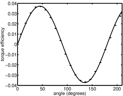
We observed that the torque acting on an elongated particle in a plane polarized beam had the predicted sinusoidal dependence on the angle between the long axis of the particle and plane of polarization of the beam. This dependence is shown in figure 3.
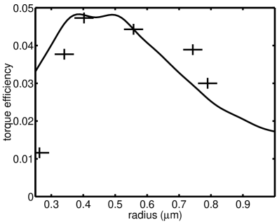
We measured the maximum torque, which occurs at , acting on rods of various sizes. We note close agreement between the theoretical predictions and our experimental observations, as shown in figure 4. The maximum torque versus radius occurs when the rod radius is approximately equal to the beam waist radius. Smaller rods do not intercept the entire beam, resulting in lower torque, while larger rods appear more uniform to the beam, again resulting in lower torque.
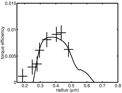
We also measured the spin component of the torque produced by a circularly polarized incident beam; this is shown in figure 5. This torque is significantly smaller than the torque produced by a plane polarized beam, which is presumably the reason for it not having been observed before. However, since the torque in this case is independent of angle, it may prove to have useful practical applications.
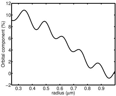
In all of these cases, we note that the orbital component of the total torque is very small—the total torque can be accurately determined by measurement of the spin component of the the torque. The fraction of the torque due to the orbital component is shown in figure 6, with the orbital torque contributing about 1–10% to the total torque. We note that the orbital component of the torque is partly due to the fact that a strongly focussed circularly polarized beam carries orbital angular momentum as well as spin Nieminen et al. (submitted for publication). Such an orbital component of total angular momentum will be converted to spin angular momentum as the light is recollimated by the condenser. Numerical integration of the light collected by the condenser shows that, within numerical error, all of the orbital torque is due to the polarization of the beam, and is converted to spin angular momentum by the condenser. Therefore, most of the orbital torque can be directly measured. A small amount of orbital torque due to large-angle scattering is expected, but since light scattered at large angles from the beam axis cannot be collected by the condenser, this contribution to the torque is unmeasurable in our experiment. Since the refractive index contrast is small, only a small amount of light will be lost through large-angle scattering. Smaller particles scatter the lower-order multipole components of the beam more strongly; these components are more convergent, resulting in a larger proportion of torque due to orbital angular momentum.
Finally, we can compare our torque measurements against the properties of the fluid in which the rods rotated (water), which is independent of our theoretical predictions. The torque acting on a rod due to viscous drag can be estimated Tirado and García de la Torre (1980); for a rod of length 5.0 m and radius 0.34 m, with a measured rotation rate of 7.8 Hz, the torque due to viscous drag is approximately 2.5 pNm %, in close agreement with the optically measured torque of pNm (and the theoretically predicted torque of pNm).
VI Discussion and summary
We found that this method of rotation generated sufficient torque to be useful, with 150 pNm per watt of trapping power being typical. Three-dimensionally trapped flattened particles simultaneously align with both the beam axis and the plane of polarization of plane-polarized light or rotate freely in circularly polarized light. Elongated particles experience a torque about the beam axis, and if they are unable to, or are prevented from, aligning with the beam axis, can be rotated or aligned by this torque. Elongated particles smaller than the beam waist do not tend to align with the beam axis, and the method is readily applicable for small particles. The modified tweezers apparatus can also be used for rotating and aligning particles of birefringent material, which generate much higher torques, extending the usefulness of the modification.
If a plane-polarized trapping beam is used, the trapped particle can be aligned in a desired direction, or, using some method to rotate the plane of polarization (we used a motorised waveplate, but electro-optic methods could also be used), rotated at a constant rate. If a circularly polarized trapping beam is used, the trapped particle can be rotated by a constant torque. Thus, our method of rotation can be used for the production of either constant-speed or constant-torque micromotors, as well as for the manipulation of microscopic specimens.
The optical torque acting on the particle can be measured by optical means. In principle, it is possible to measure the total optical torque, but in practice, it is far simpler to measure only the spin component of the torque. Our calculations show that for a wide range of particle shapes, sizes, and compositions, the resulting torque is dominated by the contribution from spin angular momentum, and a good degree of accuracy can be obtained by measurement of the spin torque alone. The calculated ratio of the spin and orbital contributions to the torque can be used to obtain a good estimate of the orbital torque, improving the accuracy of the measurement. Since the spin torque approaches the total torque for low refractive index contrast particles, such as most biological specimens, the orbital torque will be unimportant for many cases. The orientation of the particle can also be determined from the transmitted polarization. Combined optical torque and orientation measurement could prove to be a useful quantitative technique for biological applications. For example, the dependence on the applied torque of the angular displacement of organelles within living cells could be measured, giving information about the mechanical properties of the anchoring cytoskeleton. In addition, the optical torque can be used to determine the optical properties of the organelle, yielding information about its composition and structure.
References
- Ashkin et al. (1986) A. Ashkin, J. M. Dziedzic, J. E. Bjorkholm, and S. Chu, Opt. Lett. 11, 288 (1986).
- Ashkin (2000) A. Ashkin, IEEE J. Select. Topics Quantum Electron. 6, 841 (2000).
- Nieminen et al. (2001a) T. A. Nieminen, N. R. Heckenberg, and H. Rubinsztein-Dunlop, Journal of Modern Optics 48, 405 (2001a).
- Friese et al. (2001) M. E. J. Friese, H. Rubinsztein-Dunlop, J. Gold, P. Hagberg, and D. Hanstorp, Applied Physics Letters 78, 547 (2001).
- Galajda and Ormos (2001) P. Galajda and P. Ormos, Applied Physics Letters 78, 249 (2001).
- Bayoudh (1999) S. Bayoudh, Master’s thesis, Department of Physics, The University of Queensland, Brisbane, Australia (1999).
- Bayoudh et al. (in press) S. Bayoudh, T. A. Nieminen, N. R. Heckenberg, and H. Rubinsztein-Dunlop, Journal of Modern Optics (in press).
- Bonin et al. (2002) K. D. Bonin, B. Kourmanov, and T. G. Walker, Opt. Express 10, 984 (2002).
- Galajda and Ormos (2003) P. Galajda and P. Ormos, Opt. Express 11, 446 (2003).
- Mishchenko (1991) M. I. Mishchenko, Journal of the Optical Society of America A 8, 871 (1991).
- Waterman (1971) P. C. Waterman, Physical Review D 3, 825 (1971).
- Nieminen et al. (2003a) T. A. Nieminen, H. Rubinsztein-Dunlop, and N. R. Heckenberg, J. Quant. Spectrosc. Radiat. Transfer 79-80, 1019 (2003a).
- Mishchenko et al. (2000) M. I. Mishchenko, J. W. Hovenier, and L. D. Travis, eds., Light scattering by nonspherical particles: theory, measurements, and applications (Academic Press, San Diego, 2000).
- Padgett and Allen (2000) M. Padgett and L. Allen, Contemporary Physics 41, 275 (2000).
- Simpson et al. (1997) N. B. Simpson, K. Dholakia, L. Allen, and M. J. Padgett, Opt. Lett. 22, 52 (1997).
- Friese et al. (1996) M. E. J. Friese, J. Enger, H. Rubinsztein-Dunlop, and N. R. Heckenberg, Physical Review A 54, 1593 (1996).
- Friese et al. (1998) M. E. J. Friese, T. A. Nieminen, N. R. Heckenberg, and H. Rubinsztein-Dunlop, Nature 394, 348 (1998), erratum in Nature, 395, 621 (1998).
- Higurashi et al. (1999) E. Higurashi, R. Sawada, and T. Ito, Physical Review E 59, 3676 (1999).
- Luo et al. (2000) Z.-P. Luo, Y.-L. Sun, and K.-N. An, Applied Physics Letters 76, 1779 (2000).
- Ukita and Kanehira (2002) H. Ukita and M. Kanehira, IEEE J. Select. Topics Quantum Electron. 8, 111 (2002).
- Paterson et al. (2001) L. Paterson, M. P. MacDonald, J. Arlt, W. Sibbett, P. E. Bryant, and K. Dholakia, Science 292, 912 (2001).
- Sato et al. (1991) S. Sato, M. Ishigure, and H. Inaba, Electron. Lett. 27, 1831 (1991).
- Santamato et al. (2002) E. Santamato, A. Sasso, B. Piccirillo, and A. Vella, Opt. Express 10, 871 (2002).
- O’Neil and Padgett (2002) A. T. O’Neil and M. J. Padgett, Opt. Lett. 27, 743 (2002).
- Heckenberg et al. (1992) N. R. Heckenberg, R. McDuff, C. P. Smith, and A. G. White, Opt. Lett. 17, 221 (1992).
- Jones (1945) R. C. Jones, Physical Review 68, 93 (1945).
- Born and Wolf (1997) M. Born and E. Wolf, Principles of Optics (Cambridge University Press, Cambridge, 1997), 6th ed.
- Kralik et al. (1995) J. C. Kralik, B. E. Vugmeister, and M. S. Malcuit, Phys. Rev. A 51, 1532 (1995).
- Palmer (1980) A. J. Palmer, Opt. Lett. 5, 54 (1980).
- Sakai et al. (1999) H. Sakai, C. P. Safvan, J. J. Larsen, K. M. Hilligsœ, K. Hald, and H. Stapelfeldt, J. Chem. Phys. 110, 10235 (1999).
- Nieminen et al. (2001b) T. A. Nieminen, H. Rubinsztein-Dunlop, and N. R. Heckenberg, Journal of Quantitative Spectroscopy and Radiative Transfer 70, 627 (2001b).
- Nieminen et al. (2001c) T. A. Nieminen, H. Rubinsztein-Dunlop, N. R. Heckenberg, and A. I. Bishop, Computer Physics Communications 142, 468 (2001c).
- Farsund and Felderhof (1996) Ø. Farsund and B. U. Felderhof, Physica A 227, 108 (1996).
- Jackson (1999) J. D. Jackson, Classical Electrodynamics (John Wiley, New York, 1999), 3rd ed.
- Nieminen et al. (2003b) T. A. Nieminen, H. Rubinsztein-Dunlop, and N. R. Heckenberg, J. Quant. Spectrosc. Radiat. Transfer 79-80, 1005 (2003b).
- Brock (2001) B. C. Brock, Sandia report SAND2000-2217-Revised, Sandia National Laboratories, Albuquerque, New Mexico, USA (2001).
- Crichton and Marston (2000) J. H. Crichton and P. L. Marston, Electronic Journal of Differential Equations Conf. 04, 37 (2000).
- Choi et al. (1999) C. H. Choi, J. Ivanic, M. S. Gordon, and K. Ruedenberg, Journal of Chemical Physics 111, 8825 (1999).
- Gouesbet (1996) G. Gouesbet, Applied Optics 35, 1543 (1996).
- Nieminen et al. (submitted for publication) T. A. Nieminen, N. R. Heckenberg, and H. R. Rubinsztein-Dunlop (submitted for publication).
- Tirado and García de la Torre (1980) M. M. Tirado and J. García de la Torre, J. Chem. Phys. 73, 1986 (1980).