Also at ]General Physics Institute RAS, Vavilov str. 38, Moscow 119991, Russia
Also at ]Moscow Institute of Physics and Technology, Institutskij per. 9, Dolgoprudny Moscow region 141700, Russia
Ultrahigh Light Intensification
by a Counter-Propagating Breaking Plasma Wave
– Relativistic Flying Parabolic Mirror
Abstract
A method to generate ultrahigh intense electromagnetic fields is suggested, based on the laser pulse compression, carrier frequency upshift and focusing by a counter-propagating breaking plasma wave, relativistic flying parabolic mirror. This method allows us to achieve the quantum electrodynamics critical field (Schwinger limit) with present day laser systems.
pacs:
12.20.-m, 13.40.-f, 52.27.Ny, 52.38.-r, 52.65.RrThe invention of chirped pulse amplification (CPA) method and recent development of laser technology led to a stunning increase of the light intensity in a laser focal spot, Mourou2 . Electrons in laser electromagnetic field become relativistic at intensities W/cm2. The ion motion strongly affects the relativistic plasma dynamics starting from W/cm2 (see Ref. B-review and references therein). Nowadays lasers produce pulses whose intensity is approaching to W/cm2 Mourou2 . With further increase of intensity we shall meet novel physical processes such as the radiation reaction dominated regimes, which come into play at W/cm2 Zhidkov , and then the regime beyond W/cm2 where the quantum electrodynamics (QED) description is needed as the recoil of emitted photon momentum becomes comparable with the electron momentum B2 . Near the intensity of W/cm2, corresponding to the QED critical electric field, light can generate electron-positron pairs from vacuum el-pos1 ; el-pos2 . Even before that limit, vacuum begins to act nonlinearly such as vacuum polarization. These nonlinear effect have attracted a great deal of attention since el-pos1 : they lie outside the scope of perturbation theory and shed light on the nonlinear quantum electrodynamics properties of the vacuum. There are several ways to achieve such an intensity. One way was demonstrated in the experiments SLAC96 , where high-energy bunch of electrons interacts with counterpropagating intense laser pulse. In the reference frame of electrons the electric field magnitude of the incident radiation was approximately 25% of the QED critical field.
A technically feasible way is to increase the power of the contemporary laser system by some 7 orders of magnitude through megajoule lasers TM , albeit quite expensive. Another way is to increase the frequency of the laser radiation and then focus it onto a tiny region. In this method X-ray lasers can be used Ringwald . To achieve more “moderate” intensities, W/cm2, another scheme was suggested in Ref. Shen-Yu02 , where a quasi-soliton wave between two foils is pumped by the external laser field up to an ultrahigh magnitude. Another method is based on the simultaneous laser frequency upshifting and the pulse compression. These two phenomena were demonstrated in a broad variety of configurations, where they were caused, in general, by different mechanisms. In particular, the wave amplification reflected at the moving relativistic electron slab was discussed in Refs. Landecker-52 (based on the frequency up-shift of radiation reflected at the relativistic mirror, as predicted by A. Einstein in Ref. Ein ); the backward Thompson scattering at relativistic electron bunch was considered in Refs. Arutyunian-63 ; the reflection at the moving ionization fronts has been studied in Refs. Semenova-67 ; “photon acceleration”schemes with co-propagating laser pulses in underdense plasma were examined in Refs. Photon-Accelerator ; various schemes of the counter-propagating laser pulses and the use of parametric amplification process were discussed in Refs. Shvets-98 .
In the present paper we consider a plasma wakefield in the wave-breaking regime as a tool for generating a coherent radiation of ultra-high intensity. Compared to the previously discussed schemes this regime demonstrates both the robustness and coherence of the transformed laser light.
We examine the following scenario. A short intense laser pulse (the“driver pulse”) induces wakefield in a plasma. As it is well known Tajima-Dawson , the wakefield phase velocity equals the laser pulse group velocity, which is close to the speed of light in a vacuum when the laser pulse propagates in the underdense plasma. The corresponding Lorentz factor is , where is the driver pulse frequency, is the Langmuir frequency. The nonlinearity of strong wakefield causes a nonlinear wave profile, including a steepening of the wave and formation of localized maximums in the electron density – the spikes Akhiezer-Polovin . This amounts to wavebreaking regime (see Ref. B-review and references therein). Theoretically the electron density in the spike tends to infinity, but remains integrable B-review . Sufficiently weak counter-propagating laser pulse (the “source pulse”) will be partially reflected from the density maximum. The reflection coefficient scales as and the reflected wave vector-potential scales as , as it is shown below. As we see, the electron density maximum acts as a mirror flying with the relativistic velocity . The frequency of the reflected radiation is up-shifted by factor , in accordance with the Einstein formula Ein . It is important that the relativistic dependence of the Langmuir frequency on the driver pulse amplitude causes parabolic bending of constant phase surface of the plasma wave, since the driver pulse has a finite transverse size D-shape . As a result, the surface where the electron density is maximal has a shape close to a paraboloid. Because we have a curved mirror, the frequency of the reflected radiation depends on the angle:
| (1) |
where is the source pulse frequency, and is the angle between the reflected wave vector and the direction of the driver pulse propagation in the laboratory frame. The curved mirror focuses the reflected light. The focal spot size is of the order of the diffraction limited size. In the reference frame of the wakefield it is , where is the wavelength of the source pulse. In the laboratory frame the focal spot size is approximately along the paraboloid axis, and in the transverse direction. In the focal spot the resulting intensity gain factor scales with as , where is the diameter of the efficiently reflected portion of the source pulse beam. This value can be great enough to substantially increase the intensity of the reflected light in the focus, even up to the QED critical electric field.
In order to calculate the reflection coefficient, we consider the interaction of an electromagnetic wave with a maximum of the electron density formed in a breaking Langmuir wave. In the laboratory frame, this interaction can be described by the wave equation
| (2) |
where is the -component of the vector potential, is the electron Lorentz factor, and near the maximum of the density in the wakewave wavebreaking regime.
According to the continuity equation , the electron density in the stationary Langmuir wave is given by , where the electron velocity varies from to (see Ref. Akhiezer-Polovin ), and the electron density varies from the minimal value to infinity (integrable). For the breaking plasma wakewave, in every wave period approximately a half of electrons are located in the spike of the electron density. Therefore we can approximate the electron density by , where is the wakefield wavelength and is the Dirac delta function. This approximation is valid when the density maximum thickness is sufficiently less than the collisionless skin depth and source pulse wavelength in the wakefield rest frame, i. e. when the wakefield is close to the wave-breaking regime.
In the reference frame comoving with the plasma wakewave, Eq. (2) has the same form. The Lorentz transformation to this frame is given by , , , .
We seek for solution to Eq. (2) in the form , where , , are the frequency and wavevector in the moving frame, and . Using this ansatz, from Eq. (2) in the moving frame we obtain
| (3) |
where and . This equation is equivalent to the scattering problem at the delta potential. The solution is for (incident and reflected wave), and for (transmitted wave), where and . In a nonlinear Langmuir wave, its wavelength depends on the wave amplitude Akhiezer-Polovin , and for the breaking wakewave we have . In this case . Taking into account, we find that the reflection coefficient, defined as a ratio of the reflected to the incident energy flux, in the co-moving frame is . In the laboratory frame it is
| (4) |
The intensity in the focal spot of the source pulse, reflected and focused by the electron density maximum in the laboratory frame, is increased by the factor of the order of
| (5) |
Theoretically, the actual gain can be even greater, because a) the estimation (4) corresponds to one-dimensinal case, whereas the density modulation in the 3D breaking wakewave is stronger, b) the reflectance (4) of the 3D paraboloidal mirror is greater at the periphery.
We consider the following example. A one-micron laser pulse (driver) generates wakefield in a plasma with density cm-3. The corresponding plasma wavelength is m. The Lorentz factor, associated with the phase velocity of the wakefield, is estimated as . The counter-propagating one-micron laser pulse with intensity W/cm2 (source) is partially reflected and focused by the wakefield cusp. If the efficiently reflected beam diameter is m, then, according to Eq. (5), the final intensity in the focal spot is W/cm2. The driver pulse intensity should be sufficiently high and its beam diameter should be enough to give such a wide mirror, assume W/cm2 and m. Thus, if both the driver and source are one-wavelength pulses, they carry J and J, respectively. We see that in an optimistic scenario the QED critical electric field may be achieved with the present-day laser technology!
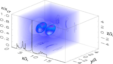
To demonstrate the feasibility of the effect of the light reflection and focusing by the breaking wakewave, we performed three-dimensional particle-in-cell (PIC) simulations using the code REMP (Relativistic Electro-Magnetic Particle-mesh code) based on scheme E-CPC . In the simulations the driver pulse propagates in the direction of the -axis. Its dimensionless amplitude is which corresponds to peak intensity W/cm, where is the driver wavelength. The driver is linearly polarized along the -axis, it has the gaussian shape, its FWHM size is . The source pulse propagates in the opposite direction. Its wavelength is two times greater than the driver wavelength, . The source pulse amplitude is chosen to be small, , to reduce the distortion of the wakewave. The pulse shape is rectangular in the -direction and Gaussian in the transverse direction, its size is . To distinguish the electromagnetic radiation of the driver from the source pulses, we set the source pulse to be linearly polarized in the direction perpendicular to the driver polarization, i. e. along the -axis. The laser pulses propagate in the underdense plasma slab with the electron density , which corresponds to the Langmuir frequency . The plasma slab is localized at in the simulation box with size . The simulations were carried out on 720 processors of the supercomputer HP Alpha Server SC ES40 at JAERI Kansai. The mesh size is , total number of quasiparticles is (ten billion). The boundary conditions are absorbing on the -axis and periodic in the transverse directon, both for the electromagnetic fields and quasi-particles. We emphasize that the simulation grid must be and in fact was chosen to be fine enough to resolve the huge frequency up-shift given by Eq.(1), exhausting all the supercomputer resources.
The simulation results are presented in Figs. 1 and 2. Fig. 1 shows the plasma wakewave induced by the driver laser pulse as modulations in the electron density. We see the electron density cusps in the form of paraboloids. They move with velocity , the corresponding gamma-factor is . Their transverse size is much larger than the wavelength of the counterpropagating source pulse in the reference frame of the wakefield. As seen from the electron density profile along the axis of the driver pulse propagation, the wakewave dynamics is close to wave-beaking regime. Each electron density maximum forms a semi-transparent parabolic mirror, which reflects a part of the source pulse radiation.
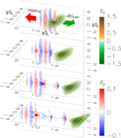
In Fig. 2 we present the electric field components. The driver pulse is seen in the cross-section of the -component of the electric field in the ()-plane. The source pulse and its reflection is seen in the cross-section of the -component of the electric field in the ()-plane. The part of the source pulse radiation is reflected from the flying paraboloidal mirrors, then it focuses yielding the peak intensity in the focal spot, and finally it defocuses and propagates as a spherical short wave train, whose frequency depend on the wave vector direction, in agreement with Eq.(1). This process is clearly seen in the animations produced from the data (see authors’ website). The main part of the reflected light power is concentrated whithin the angle , hence this coherent high-frequency beam resembles a searchlight. The reflected part has the same number of cycles as the source pulse, as expected, since it is Lorentz invriant. The wavelength and duration of the reflected pulse are approximately 14 times less than the wavelength and duration of the source pulse, in agreement with Eq.(1) since . The focal spot size of the reflected radiation is much smaller than the wavelength of the source pulse. The electric field in the focal spot is approximately 16 times higher than in the source pulse. Therefore, the intensity increases 256 times in agreement with estimation (5).
We emphasize that the efficient reflection is achievable only when the wakefield is close to the wave-breaking regime and the cusps in the electron density are formed. As we see in the simulations, the reflection and focusing is robust and even distorted (to some extent) wakewave can efficiently reflect and focus the source pulse radiation. We also observe that despite the moderate reflection coefficient, the colossal frequency up-shift and focusing by a sufficiently wide (transversely) wakewave give us a huge increase of the light intensity.
Similar processes may occur in laser-plasma interation spontaneously, e.g. when a short laser pulse exciting plasma wakewave is a subject of the stimulated backward Raman scattering or a portion of the pulse is reflected back from the plasma inhomogeneity. Then the backward scattered electromagnetic wave interacts with plasma density modulations in the wakewave moving with relativistic velocity. According to scenario described above, the electromagnetic radiation, reflected by the wakewave, propagates in the forward direction as a high-frequency strongly collimated (within the angle ) electromagnetic beam.
We have proposed the scheme of the relativistic plasma wake caustic light intensification, which can be achieved due to the reflection and focusing of light from the maximum of the electron density in the plasma wakewave at close to the wave-breaking regime. The presented results of 3D PIC simulations provide us a proof of principle of the electromagnetic field intensification during reflection of the laser radiation at the flying paraboloidal relativistic mirrors in the plasma wakewave. With the ideal realization of the described scheme we can achieve extremely high electric fields (in the laboratory reference frame) aproaching the QED critical field with the present-day laser technology. We envision the present example is just one manifestation of what we foresee as the emergence of relativistic engineering.
Acknowledgements.
We appreciate the help of APRC computer group. We thank V. N. Bayer, M. Borghesi, J. Koga, K. Mima, G. Mourou, N. B. Narozhny, K. Nishihara, V. S. Popov, A. Ringwald, V. I. Ritus, V. I. Telnov, and M. Yamagiwa for discussion.References
- (1) G. A. Mourou, C. P. J. Barty, and M. D. Perry, Phys. Today 51, No. 1, 22 (1998).
- (2) S. V. Bulanov, et. al. in: Reviews of Plasma Physics. Vol. 22, ed. by V.D. Shafranov (Kluwer Academic / Plenum Publishers, NY, 2001), p. 227.
- (3) A. Zhidkov, et al., Phys. Rev. Lett. 88, 185002 (2002).
- (4) S. V. Bulanov, T. Zh. Esirkepov, J. Koga, and T. Tajima, in preparation.
- (5) W. Heisenberg and H. Z. Euler, Z. Phys. 98, 714 (1936); J. Schwinger, Phys. Rev. 82, 664 (1951).
- (6) E. Brezin and C. Itzykson, Phys. Rev. D 2, 1191 (1970); N. B. Narozhny and A. I. Nikishov, Sov. Phys. JETP 38, 427 ( 1974); V. S. Popov, JETP 94, 1057 (2002).
- (7) C. Bula, et al., Phys. Rev. Lett. 76, 3116-3119 (1996).
- (8) T. Tajima and G. Mourou, Phys. Rev. ST Accel. Beams 5, 031301 (2002).
- (9) A. Ringwald, Phys. Lett. B 510, 107 (2001); R. Alkofer, et al., Phys. Rev Lett. 87, 193902 (2001); T. Tajima, Plasma Phys. Rep. 29, 207 (2003).
- (10) B. Shen and M. Y. Yu, Phys. Rev. Lett. 89, 275004 (2002).
- (11) K. Landecker, Phys. Rev. 86, 852 (1952); L. A. Ostrovskii, Soviet Physics Uspekhi 116, 315 (1976).
- (12) A. Einstein, Ann. Physik 17, 891 (1905).
- (13) F. R. Arutyunian and V. A. Tumanian, Phys. Lett. 4, 176 (1963); Y. Li, et. al., Phys. Rev. ST Accel. Beams 5, 044701 (2002).
- (14) V. I. Semenova, Sov. Radiophys. Quantum Electron. 10, 599 (1967); W. B. Mori, Phys. Rev. A 44, 5118 (1991); R. L. Savage, Jr., et al., Phys. Rev. Lett. 68, 946 (1992).
- (15) S. C. Wilks, et al., Phys. Rev. Lett. 62, 2600 (1989); C. W. Siders, et al., Phys. Rev. Lett. 76, 3570 (1996); Z.-M. Sheng, et al., Phys. Rev. E 62, 7258 (2000).
- (16) G. Shvets, et. al., Phys. Rev. Lett. 81, 4879 (1998); Y. Ping, et. al., Phys. Rev. E 62, R4532 (2000); P. Zhang, et al., Phys. Plasmas 10, 2093 (2003); N. J. Fisch and V. M. Malkin, Phys. Plasmas 10, 2056 (2003).
- (17) T. Tajima and J. Dawson, Phys. Rev. Lett. 43, 262 (1979).
- (18) A. I. Akhiezer and R. V. Polovin, Sov Phys. JETP 30, 915 (1956).
- (19) S. V. Bulanov and A. S. Sakharov, JETP Lett., 54, 203 (1991).
- (20) T. Zh. Esirkepov, Comput. Phys. Comm. 135, 144 (2001).