A straw drift chamber spectrometer for studies of rare kaon decays
Abstract
We describe the design, construction, readout, tests, and performance of planar drift chambers, based on 5 diameter copperized Mylar and Kapton straws, used in an experimental search for rare kaon decays. The experiment took place in the high-intensity neutral beam at the Alternating Gradient Synchrotron of Brookhaven National Laboratory, using a neutral beam stop, two analyzing dipoles, and redundant particle identification to remove backgrounds.
keywords:
straw drift chambers, wire chambers, particle tracking, spectrometer, high rate, rare kaon decaysPACS:
29.40.Cs , 29.40.Gx,
,
,
,
,
,
,
,
,
,
,
,
,
,
,
,
,
,
,
,
,
,
,
,
,
,
,
,
,
,
,
,
,
,
,
(BNL E871 Collaboration)
1 Introduction
We present a comprehensive description of a two-arm tracking system consisting of eight planar drift chambers based on 5 diameter straws designed, constructed, and operated in Alternating Gradient Synchrotron experiment 871 at Brookhaven National Laboratory. Following a brief motivation for the experiment, we describe mechanical and electronics design considerations, important construction details, and three years experience in operating the system.
1.1 Physics motivation
Despite abundant experimental confirmations of the Standard Model of elementary particles and interactions, the theory is generally perceived as incomplete, or a low energy realization of a more general theory with a full symmetry at higher energy. There are indeed many basic questions to which answers will have to come from outside the current model. This is the main motivation for theoretical and experimental explorations beyond the Standard Model. In particular, lepton flavor violation occurs naturally in many extensions of the Standard Model; the process is a sensitive probe of such violation. In general, rare kaon decay experiments provided a promising avenue for discovering phenomena outside the Standard Model.
The primary goal of experiment E871 was to search for separate lepton number violation in the decay . The experiment achieved a 90% C.L. limit of [1], thus probing new interactions in nature in the 200-TeV mass scale. To achieve this sensitivity, the experiment ran with the very high beam intensities made possible by the Booster at the AGS.
The experiment also made the first observation of the decay , measuring a branching fraction of based on four observed events [2]. Over 6,000 thousand events were also observed, for a branching fraction of , reducing the uncertainty for this decay mode by a factor of three compared to previous attempts [3].
1.2 Experimental setup
Two important experimental elements relevant to this work were the AGS high-intensity neutral beam and the E871 two-arm spectrometer. A novel beam stop [4, 5] was located in the upstream spectrometer magnet to improve downstream acceptance, tracking, and particle identification.

The essential requirements on the spectrometer were good kinematic reconstruction and reliable, redundant particle identification, both to be accomplished in a high rate environment. The spectrometer, shown in Figure 1, was built in the B5 beam line of the AGS. The neutral beam was produced by an intense primary 24.1 GeV/c beam of up to 1.71013 protons delivered in a 1.6 s spill onto a 1.5-interaction-length platinum target. A system of sweeping magnets and collimators angled at 3.75∘ with respect to the proton beam direction formed a neutral beam with mostly neutrons and kaons at an approximate solid angle of . Particles emerging from the 11 m long evacuated decay volume were tracked and identified in the E871 spectrometer. The main features of the apparatus were:
-
•
two magnets for redundant momentum measurement, tuned to form a “parallel trigger” for two-body decays (i.e., charged particles traveling downstream of the second analyzing magnets triggered the apparatus only if they traveled nearly parallel to the neutral beam direction);
-
•
a beam-stop placed in the first magnet to absorb the neutral beam
-
•
redundant finely-segmented fast straw drift chambers, followed by conventional drift chambers in regions of lower rate
-
•
redundant particle identification of muons and electrons
-
•
multi-level trigger with fast on-line reconstruction
-
•
fast custom-designed massively-parallel data acquisition system.
The neutral beam was absorbed in a beam stop specially designed and tested for this configuration. The effective strengths of the magnetic fields ( and MeV/c) were set such that trajectories of two-body kaon decays emerged nearly parallel to the neutral beam direction downstream of the second magnet [5]. Such an arrangement simplified triggering and provided the first level rejection of the three-body decays.
The intense primary proton beam produced roughly decays per AGS spill, resulting in high hit rates in the upstream straw drift chambers. Additional rates in chambers resulted from leakage of low energy particles (mainly charged, but also neutrons and photons) from the beam-stop. The beam stop shielded the downstream part of the spectrometer, where rates were substantially reduced, thus minimizing the probability of pattern-recognition or particle-identification errors. Rejection of background due to common kaon decays depended crucially on precise, redundant and low-occupancy tracking.
1.3 Tracking system requirements
Since tracking resolution at low momentum is dominated by multiple Coulomb scattering, maximal background suppression required that the tracking system be low mass, efficient, redundant, fast (i.e., possess low occupancy), and provide good position measurement. When designing experiment 871 the following requirements for the tracking were thus imposed:
-
1.
minimize multiple Coulomb scattering by limiting the amount of material;
-
2.
provide tracking redundancy with low rate of wire failures and low cell occupancy;
-
3.
provide high hit efficiency for minimum ionizing particles;
-
4.
sustain good position resolution in high rate environment;
-
5.
assure good vertex reconstruction of two-body decays.
The corollary from the above list are general hardware features desired of the system:
-
•
high segmentation (i.e., small cell size)
-
•
fast drift velocity gas
-
•
fast-timing electronics with short pulse tails
-
•
minimal cross-talk
-
•
mechanical robustness.
We discuss the design and material choices made to accomplish the above requirements in the following sections.
2 Mechanical design

As Figure 1 illustrates, there were two straw stations between the decay tank and first spectrometer magnet, and two more between the magnets, followed by two conventional drift chamber stations downstream of the second magnet. An assembly drawing of a complete chamber module with and views is shown in Figure 2.
2.1 Choice of materials
The technical possibility of making thin-wall tubes suggested the replacement of traditional drift chambers — with the electric field shaped by wires — by chambers based on a continuous cylindrical cathode surface, or “straw”. The name derives from the manufacturing process, which is similar to that of paper drinking straws. Thin, small straws with wall thicknesses of approximately 30 and -mm diameter, were originally used in the vertex detectors of several high energy physics experiments at e+e- colliders [6], as well as in balloon flight experiments [7]. They will be part of the ATLAS detector at the CERN Large Hadron Collider [8].
Table 1 summarizes the amounts of material in an individual tracking chamber, expressed in units of radiation length. The traditional 20 gold-plated tungsten wire was used for the anode. As shown in the table, the total radiation thickness of a typical E871 straw chamber was of radiation length. The thickness of conventional drift chambers was very similar.
| mean | radiation | |||
|---|---|---|---|---|
| thickness (cm) | layers | (cm) | thickness (% ) | |
| Mylar windows | 0.001270 | 2 | 28.7 | 0.00885 |
| helium | 21.434 | 1 | 529888.0 | 0.00374 |
| Mylar straw | 0.00798 | 111 | 28.7 | 0.16683 |
| copper (1000 Å) | 0.000031 | 5 | 1.430 | 0.01098 |
| (50%) | 0.3980 | 2.5 | 9313.0 [9] | 0.01068 |
| (50%) | 0.3980 | 2.5 | 34035.0 | 0.00292 |
| tungsten wire | 0.0000062 | 5 | 0.350 | 0.00886 |
| epoxy | 0.000150 | 1 | 35 | 0.00043 |
| Total | 0.21329 |
The materials most often used for straw walls are polyester (e.g. Mylar [10]) and polyimide (such as Kapton [11]). In our experience Kapton has the better dimensional stability of the two. Mylar straws installed for the 1995 run of E879 showed signs of shrinkage over the course of the running period, making the individual straws appear twisted. This motivated our move to Kapton for rebuilt 1996 chambers; these chambers displayed no such effect. We attribute this difference in stability to the higher water content of Mylar relative to Kapton; Mylar became more brittle or “crinkly” with age — a sign of dehydration.
Two metals are typically considered for cathode lamination: aluminum and copper. Another option is a carbon-doped substrate material with controlled resistivity. At the time of our construction, doped Polycarbonate sheets were available and we explored their use [12]. However, the thinnest sheets available were 15, and since Polycarbonate is mechanically weaker than Mylar, we did not pursue this option. The use of resistive substrate and copper cathodes was motivated by effects related to the aging/oxidizing of the aluminum cathode, as it had been suggested that a (semi-) conductive base material would remedy some of these problems. Similar comments can be made about Kapton. The thickness of Mylar and Kapton can be controlled with high precision; thin foils can be as little as 2 thick. Metalizing Mylar or Kapton up to 1000 Å is easy and inexpensive. Combining Mylar or Kapton with copper provided a strong straw base and led to less severe anode aging.
Copper lamination was chosen because of its much better electrical aging properties than aluminum. Copper oxide is a semiconductor, which should lessen the possibility of cathode field-emission effects, as opposed to aluminum dioxide, which is an insulator. Copper cathodes also have a relatively high work function, which provides some soft-photon absorption at the straw walls.
2.2 Physical design considerations
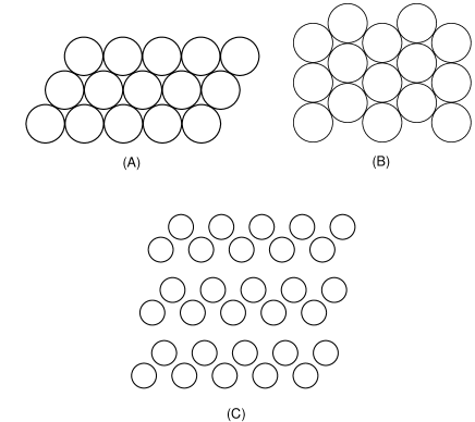
We studied several possible planar cell patterns, trying to optimize efficiency and redundancy while minimizing radiation thickness and construction complexity. The configurations fall into three categories: close-packed (Figure 3(A)), rotated close-packed (Figure 3(B)), and staggered (Figure 3(C)). Close-pack arrangements are bonded together along the straw, forming self-supporting structures, while staggered designs require individually tensioned straws.
The self-supporting nature of close-pack designs offers simplicity of design, since the array needs no external tension. Staggered straws offer greater flexibility, with a flatter distribution of mean path lengths across the active area of the chamber, but require tension to keep from sagging.
We studied the relative hit multiplicities of the various geometries via Monte Carlo simulation for the acceptance for tracks with angle ranges with respect to the neutral beam direction of to 250, 20 to 250, and 20 to 150 mr. To maintain high redundancy, we wanted to minimize the number of tracks for which two or fewer hits were observed per single-view tracking station. The simulation used the straw’s inner diameter of 0.5 cm as the size of the active area of each straw. Simulated E871 tracks were projected onto the plane and any track crossing a straw’s active area was considered a hit.
The studied geometries are shown in Figure 3 and summarized in Table 2. In the first design, a conventional 3-view close-pack, the finite straw-wall thickness allowed some 2-hit tracks. The mean straw density was 1.97 straws/cm/view. The second design, a “rotated” close pack, allowed no 2-hit tracks, while some tracks could have as many as 6 hits. The straw density here was higher: 2.27 straws/cm/view. Both designs required straws to be glued together for mechanical stability. The third design was a staggered-straw geometry. This design presented a smoother gas path-length distribution and might have allowed replacement of individual straws. Moreover the position of the offset straw could be placed off-center in order to optimize the chamber for a desired angular acceptance. All geometries are shown for three measurement views.
| 1.97 straws/cm | |||||||
|---|---|---|---|---|---|---|---|
| Percent -hits | |||||||
| N.N. | |||||||
| A | 0.508 | 2.97 | 2.7 | 97.3 | 0.0 | 0.0 | 0.0 |
| C | 0.683 | 2.97 | 13.1 | 76.5 | 10.3 | 0.0 | 0.0 |
| D | 0.578 | 2.96 | 9.7 | 84.3 | 6.1 | 0.0 | 0.0 |
| E | 0.651 | 2.97 | 11.7 | 79.4 | 9.0 | 0.0 | 0.0 |
| 2.27 straws/cm | |||||||
|---|---|---|---|---|---|---|---|
| Percent -hits | |||||||
| N.N. | |||||||
| B | 0.506 | 3.45 | 0.0 | 66.5 | 23.3 | 9.0 | 1.2 |
| C | 0.635 | 3.47 | 0.1 | 57.0 | 39.1 | 3.8 | 0.0 |
| D | 0.686 | 3.46 | 0.0 | 57.1 | 40.4 | 1.9 | 0.7 |
| E | 1.025 | 3.17 | 0.2 | 83.0 | 16.3 | 0.6 | 0.0 |
Table 2 compares the close-pack and rotated close-pack geometries to staggered straws at the same straw density. All configurations with 2.27 straws/cm/view appear to be hit-equivalent. The view densities used here should be considered the two extremes. Only a skewed-stagger design, which provides plenty of straw-to-straw separation while still limiting the 2-hit probability and view density, allows a continuous density adjustment.
In summary, we found that the rotated close-pack and staggered designs with 2.27 straws/cm/view had similar hit characteristics. The mean numbers of hits were 3.45 and 3.46 respectively and neither had appreciable 2-hit probability. Due to the unavoidable dead space between adjacent straws, the conventional close-pack design allowed about 3% 2-hit tracks.
The tensioning required of staggered configurations would make chambers susceptible to “creep”, or relaxation of tension, which is expected from any plastic stretched beyond its glass transition point. In laboratory testing we observed this effect in our Mylar straws. While tensioning or gluing of the (vertical-straw) view would have been unnecessary; views, with horizontal straws, required either tension or structural support to maintain shape. Prototype chambers of both close pack and individually-tensioned, staggered straws were built and tested in cosmic-ray telescopes and in the AGS neutral beam, but the technical challenges associated with the individually-tensioned configuration led us to choose the conventional close pack design for the E871 spectrometer.
2.3 Mechanical assembly
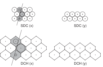
Close-pack cell configurations for the E871 straw chambers are shown in comparison to those of our conventional drift chambers in Figure 4. For redundancy in the momentum-measuring horizontal plane, the -measuring views each had a redundant, third plane of drift cells. Each drift cell in the straw drift chambers consisted of a 5-mm diameter cylindrical copper-plated Mylar or Kapton cathode [13, 14] with a 20-micron gold-plated tungsten sense wire [15] along its axis. The cylindrical cathodes were wound on precision mandrels, where they were built up from two 25.4- layers of material bonded with a thin layer of 4-8 of adhesive. The inner layer had the 0.1-m copper layer vapor-deposited [16] on one side which faced the inside of the straw tube. The original straws in the experiment were made of Mylar. However, all but one of the chambers (called SDC4LY) were rebuilt with Kapton for the 1996 run period. Cylindrical brass sleeves provided the mechanical support and electrical contact between the straws and the end-plates. Feedthroughs pass through the end-plates and into the sleeves.
| diameter | 5 mm |
|---|---|
| material | Mylar (1995), Kapton (1996) |
| wall construction | two 12.5-m windings separated by 8-m adhesive |
| cathode | .1-m copper plate, providing 1 resistivity |
| anode wire | 20-m, 4% gold-plated tungsten |
| mean thickness | per layer |
| gas pressure | 1 atmosphere |
| high voltage | 1950–1975 V |
| max. drift time | 25 in CF4-C2H6 (1:1) |
Individual straws were bonded into closely-packed arrays whose cross section is shown in Figure 4. Sense wires were precisely positioned within the straws by molded Ultem [17] inserts, which also acted as gas feedthroughs. Ground contact between the copper cathodes and the aluminum chamber frames was made through gold-plated brass sleeves, which were press-fit onto the Ultem feedthroughs and silver-epoxied into the straws. More silver epoxy formed the electrical contact between the sleeves and the chamber frames, while also providing a gas seal. Figures 5,6,7 show a cross-section assembly drawing of the inserts, sleeves, and end-plate gas manifold. A more detailed end-plate assembly for one of the chambers, including amplifier-card mounting and gas connections, is shown in Figure 8. The straw drift chamber characteristics are summarized in Table 3.


The feedthrough assembly served a number of functions, including positioning, tensioning, and electrically isolating the anode wire from the end-plate. It also supported the electrical contact of the anode wire to the outside signal and high voltage, and provided gas flow into or out of the straw. A sketch of the end-plate and feedthrough assembly is shown in Figure 5.
The wire was positioned at the center of the straw at the feedthrough with a precision of about 25 using a V-shaped groove molded into the feedthrough near one end (Figure 7). Tension was maintained with a brass pin inserted and clamped into the slotted Ultem end opposite the V-groove. The pin diameter, about 50 smaller than the inside diameter of the feedthrough, allowed the anode wire to extend along the pin. The wire was compressed between the brass pin and the (slotted) feedthrough wall with an Ultem ring, which slid over the outside of the feedthrough.The pin end of the feedthrough, the pin, and the compression ring extended outside the chamber end-plate.

The Ultem material had a resistance of at least 100 M through its wall thickness of 0.10 inches. Gas was supplied to the straw tubes in parallel through a gas manifold milled into the end-plates. From the manifold, the gas entered the interior of the Ultem feedthrough via a pair of holes in the feedthrough walls.
Since the straw assembly was essentially irreversible, we did a test assembly of the complete chamber frame, including end-plates and corner blocks. This was then dismantled for installation of straws. All straw-end pieces were deburred and cleaned in an ultrasonic bath. Prior to assembly, holes with critical clearance, such as the Ultem clearance holes in the end-plates, were tested and cleaned by inserting the requisite gauge pin. Most gas fittings were installed in the frame pieces prior to assembly, since the assembled frame had insufficient clearance for installation. With the exception of the first chamber built (called SDC2R), which had a stainless steel frame, all frame pieces were aluminum.
The straws, of Mylar or Kapton, were shipped with Tyvek [18] liners, in either PVC tubes or wooden crates. Thus the first step in the straw preparation was unpacking, de-lining, and inspection. Straws with visible inner surface irregularities (dents or lumps of glue) were rejected. Following a previous experiment [19], we constructed a simple straw cutting method consisting of a precision bored Al block, with a hole diameter about 25 larger than the outer diameter of straws, with a transverse slit cut through the bore. Cutting a straw only required insertion into the bore and sliding a razor into the slit.
| application | name | pot life | cure time |
|---|---|---|---|
| straw-insert bond | EPO-TEK EP110 silver epoxy | ||
| insert-frame bond | EPO-TEK 410E silver epoxy | ||
| straw-straw bond | EPO-TEK 301-2 epoxy | 24 h | 48 h |
| ULTEM/frame seal | TRA-BOND 2143D epoxy | 75 m | 18 h |
| outer ULTEM seal | DOW 3110 two-part RTV | 165 m | 6.5 h |
Straws were installed in each and view of each module separately. Before the two views were combined, their straws were laminated, potted, and structurally glued to the view sub-frame. Straws were held together within an array through spot application of Epo-Tek 301-2, a very liquid epoxy with an 8-hour pot life and two day cure [23]. After securing the straws precisely in place with specially-made brackets mounted on the chamber frames, epoxy was applied in small ( mm-diameter) drops to 4–6 points along each tangent between straws. A gas-pressure dispenser was used, with tubular steel tips which allowed inner straws to be reached.
At this point the two views fit loosely in their frames. Bolting and pinning the and views together completed and squared the module frame, making it possible to bond the straw arrays to the frames by applying Tra-Bond 2143D epoxy [24] around each insert outside the chamber end-plates, but still inside the gas manifold. Electrical contact between the straw inner surface (via the gold-plated brass ‘sleeve’) was made by filling the gap between straw/sleeve end and inner end-plate surface with EPO-TEK 410E silver-filled epoxy [23]. Although before installation individual straw assemblies were tested for leaks, the silver epoxy should form an additional gas seal; the 2143D epoxy forms the manifold-straw seal. The frame assembly was completed by gluing down of the manifold cover with a bead of silver epoxy joining the aluminum cover to the end-plate and filling the 2143D epoxy around each ultem insert.
Wires were installed after chamber assembly. We used 20-m, gold-plated tungsten wire. The wire was threaded through a blunted sewing needle, fed through the top insert, and lowered down the straw and out the bottom insert. To provide working clearance and hold the wire against the interior v-notch of the insert, the wire was deflected by a horizontal bar suspended below the chamber. A gold-plated brass pin was inserted into the top insert and clamped in place with an Ultem collar. Then tension was applied to the wire by clamping a 70-g mass below the bottom insert and deflecting bar (some tension was lost to friction at the bar and at the Ultem notch). Wire tension was locked in by installing another brass pin in the bottom insert, again with a clamping Ultem collar. Because of the awkward position and close-pack clearances of this step, we designed a special tool for pin installation. Once we were satisfied with the wire installation, a drop of epoxy (301-2) at each end ensured the pins and wire ends stayed in place.
We checked wire tensions by measuring the resonant frequency of a driven wire in a constant magnetic field. A custom device [28] performed the frequency measurement and provided the driving frequency, while a permanent magnet held near the wire center supplied the field. Any wires not satisfying minimum tension or standoff limits were removed and replaced.

3 Readout electronics
Signals from the straw sense wires were amplified and discriminated on 6-channel boards directly mounted on the straw end pins. The amplifier circuit (Figure 9) is a four-transistor design, decoupled from the high-power discrimination stage by a 1-to-2 transformer [29]. The gain was about 20 with less than 1.5% cross talk, and a typical operating threshold of 1.5. The digitized signal was converted to a 30-ns pulse and sent over a 333-ft long, 500-ns delay line by a 96-channel driver board, to be recorded by a 6-bit, 1.75-ns least-count TDC.

Since particle positions were determined from the drift times of ionization electrons, position resolution was directly affected by the precision of the drift-time measurement. The high particle flux expected in experiment 871 required a small cell size to minimize occupancy, with a high drift velocity gas for reduced dead time.
The small cell size of the straw chambers called for tight packing of front-end channels, increasing the possibility of cross talk. Our plan to use a drift gas, meanwhile, implied small pulse heights, requiring a high gain front-end amplifier. In addition, the front-end electronics were required to dovetail with existing equipment: 32-channel gray code TDCs with 1.875 least count [33] coupled to the front-end electronics through 97-conductor (32 ECL channel) 500 delay lines. Front-end components designed and built specifically for E871 included 6-channel amplifier/discriminator boards, which mounted directly onto the chamber frames, and 96-channel cable driver boards. A block diagram of the straw chamber electronics setup is shown in Figure 10.

Initial designs of the front end amplifier based on an integrated-circuit amplifier proved costly (more than 12 dollars per channel), while an ASIC-based design missed our time window. We therefore pursued a much less expensive option (less than five dollars per channel), based on a four-transistor discrete amplifier design. Our initial design, with high-voltage distribution and the analog amplifier circuit on the chamber-mounted board and the discriminator on a separate driver board, taught us that twist-n-flat cable made an excellent antenna. The discriminator stage was subsequently moved onto the chamber-mounted board.
The final 6-channel amplifier/discriminator layout consisted of high-voltage, analog, and digital sections coexisting on one four-layer board. Copious grounding and surface-mounted components eased the tight space constraints, while SIP sockets facilitated mounting the cards directly onto the straw end pins. The bias high voltage and front-end amplifier low-voltage power, along with odd- and even-channel pulser signals for rudimentary electronics diagnosis, were delivered by chamber-mounted busses. The digital half of the amplifier boards were supplied by a separate cable bus.
3.1 Early testing
Early bench tests with simulated straw pulses reported gains of . Stable operation was achieved at thresholds as low as 0.9 . We found that DIP-package multi-channel transformers in our original amplifier design caused too much cross talk. After replacing these with single-channel packages, cross talk between adjacent channels was reduced to 1.5%.
The front-end amplifiers were also tested on prototype straw chambers. During cosmic ray tests the amplifiers again operated at thresholds below 1, with overall straw efficiencies measured above 97%. Single-wire position resolution for the cosmic ray tests was 120 for the Ar-ethane (50-50) gas-fill.
3.2 Full-system performance
During actual data taking for E871, the complete 6500-channel straw chamber readout system performed nearly as well as in tests. Even in the noisy environment of a high energy physics experiment, all chambers operated at or below a 1.3-A threshold with a mean efficiency of 96%.
We experienced a significant board failure rate due to cold solder joints on the amplifier cards; a test stand was built to diagnose and repair these faults.
The entire mechanical design and the front-end electronics system has subsequently been copied for use in the Fermilab FOCUS experiment (FNAL 831) [27].
4 Gas system
The gas delivery system was built to handle multiple gas mixtures, applying both high- and low-pressure filtering. Its purpose was to provide an uninterrupted flow of clean gas mixture, with a constant ratio of its components while maintaining stable pressure inside and outside the straw volume. Additional attention was paid to purifying the gases, since impurities in the gas mixture can catalyze straw etching or affect the attachment coefficient, charge-carrier diffusion, or drift velocity.
In order to minimize multiple scattering effects, we flowed helium through the chamber volumes surrounding the straw tubes, while helium-filled bags occupied the spaces between chambers. The gas system had to regulate the helium flow so that differential pressure across walls was restrained and flow was sufficient to prevent accumulation of flammable gas in the helium-filled volumes.
During normal operation the detectors and a large part of the gas system were in a high radiation environment. It was critical to have remote access to the status of the gas system. Supply pressures, mixture flow rates and ratios, input and output pressures, and differential pressure across the straw walls were continuously monitored and periodically inserted into the data stream.
4.1 Choice of gas
The high beam intensity in E871 necessitated not only increased segmentation of the upstream chambers, but also the use of a gas with a higher drift velocity, thus reducing the overall occupancy.

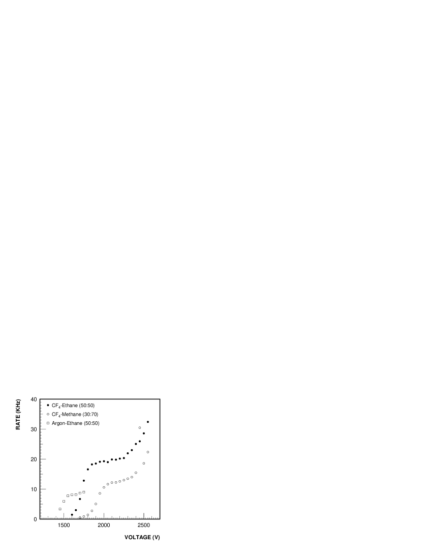
Most fast drift mixtures considered by various straw/chamber groups have been based on tetrafluoromethane [35], (also known as Halocarbon 14). Our decision to use - (50:50) was based primarily on studies performed by Heinson and Rowe [30]. They list several advantages of an ethane mixture over the commonly-used - (80:20), including a 10% higher drift velocity, safer handling, smaller radiation length, insensitivity to soft photons — they report the ethane mixture to be 25% less sensitive than isobutane. Perhaps most notably, they also found the - mixture to be less expensive and to permit a 200-V lower operating voltage. Plateau curves observed in the laboratory with a prototype chamber for this gas are shown in Figure 11 for two different radioactive sources. We chose a nominal operating voltage of 1975 V. Figure 12 compares the response of this gas to some other potential mixtures.
Figure 13 shows the drift time for this mixture as a function of distance of closest approach, along with the drift velocity and similar plots for the E871 conventional drift chambers with Ar-. We observed a drift velocity exceeding 100 m/nsec, twice that of Ar- 50:50. This factor combined with the improved segmentation ratio reduced the individual drift cell occupancy by a factor of eight over the conventional wire chambers of E791, the predecessor to E871.

4.2 Experience with prototypes
Prototype chambers were built at The University of Texas and Stanford and tested both in cosmic-ray telescopes and in the AGS neutral beam. It was during these tests that aging effects due to gas contamination began to appear.
4.2.1 Sulphur contamination
After discovering a blackening effect in straws subjected to ethane flow during the 1994 engineering run, we analyzed the interior surfaces of some of the exposed straws with Auger Electron Spectroscopy and a Scanning Tunneling Microscope. We found evidence of sulfating of copper due to sulfur contaminants in our ethane supply, and concluded that it was necessary to develop a gas filtration system for our copperized straw system.
Compounds such as H2S and SO2 are very reactive with copper, forming a black copper sulfate which in time replaces the copper, destroying the electrical conductivity of the straw and effectively removing the cathode. To solve this contamination problem, we specified a sulfur content of 0 ppm for our ethane supply, a severe restriction. In addition, we installed high-pressure catalyst and sieve filters directly on the ethane gas bottles, prior to pressure regulation.
4.2.2 Effects due to
Impurities in our freon supply were also found to cause straw aging. With a small Mylar-straw test stand, we observed that with very low flow rates of freon-based gases the conductive copper surface may be removed entirely (‘etched’) from the Mylar surface.
We observed an etching effect in a controlled experiment using a small test chamber consisting of two identical, 60-cm copperized Mylar straws. After bringing the straws to an operating voltage of 2.3 KV with -methane (30:70), we halted the gas flow and left the bias on one of the straws. This straw began to draw current after about 1.5 hours, and at 2 hours was drawing 5. Meanwhile the copper was disappearing from this straw, leaving clear Mylar. A similar test with Ar-ethane (50:50) showed no effect. To isolate the problem gas, the test was repeated with 100% ; the straw drew 60 within 5 minutes after flow was stopped, eventually leveling off at 140. After about 8 hours the copper in this straw was visibly thinner.
We have found no reports of any other observations of this effect. The most consistent mechanism is this: water vapor entered the tubes at a constant rate and with the gas flowing at some minimum value, it was flushed out. When the gas flow was stopped the water concentration in the straws built up. The hydrogen in the water reacted with some radicals to make hydrofluoric acid which attacked the copper. As a result of this study we increased our gas flow from three volume exchanges per day to ten.
4.3 Gas purification
| Impurity | Maximum Quantity |
|---|---|
| (molar ppm) | |
| CO2 | 10 |
| CO | 5.0 |
| H2O | 1.0 |
| N2 | 200 |
| O2 + Ar | 40 |
| other halocarbons | 10 |
| SF6 | 5.0 |
| total fluorides | 0.1 (ppm weight) |
The gases used were standard commercial products, including CP-grade ethane (99.0% pure) and semiconductor-grade (99.7% pure). Table 5 lists impurities found in the as supplied. As has already been observed, some of these contaminants can play a role in the acceleration of aging effects. Water, oxygen, and any halocarbons were the most undesirable impurities.
A low pressure filtration system was placed after blending the gas mixture components. Its goal was to eliminate sulfur, water, and oxygen from the gas mixture.
Ethane, derived from natural gas, can contain many parts per million (ppm) of H2S, depending on its source. While mass-spectrographic analysis indicated that the H2S level in our ethane supply was not very high, even contamination at a few ppm could destroy our thin (1000 Å) copper cathode. We therefore developed a ‘scrubbing’ system to remove the inevitable sulfur contamination.
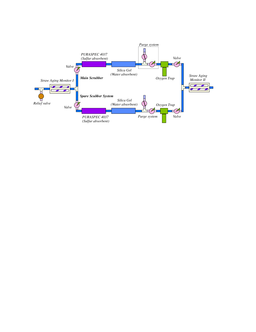
We required a simple, safe, inexpensive, self-indicating system, which ruled out many of the processes common to the petrochemical industry. However the catalyst PURASPEC 4037, a material produced by ICI Catalysts of Billingham, England [31] allows for low-pressure, low-temperature elimination of H2S from the gas stream. The catalyst is in the form of 0.1-0.2 in diameter spheres composed of 40-45% copper oxide and 20-30% zinc oxide by weight, with the balance being aluminum oxide. These metal oxides react with H2S to produce metal sulfides and water vapor. The water vapor must then be removed by a second trap, which consisted of silica or alumina gel.
The scrubbing system thus took shape as two 8-in long, 1.5-in diameter glass cylinders, one filled with PURASPEC 4037 and a second with silica gel. The cylinders were tapered at each end to allow connection to the rest of the gas system, while the absorbent materials were contained within the cylinders between plugs of glass wool. Glass cylinders were used to take advantage of the self indicating feature of the absorbents, since PURASPEC 4037 turns from gray/green to black when loaded with sulfur, while alumina gel turns from blue to pink when saturated with water. We included a redundant scrubbing line to prevent disruption during absorber replacement. Heavy-walled glass was used throughout. To prevent overpressure, we installed a check valve with a crack pressure of 20 psi before the scrubber system. An oxygen trap [32] completed the scrubber system.
Immediately upstream and downstream of the scrubber system, we installed reaction monitors, consisting of clear plexiglas tubes containing copper straws. They were used as indicators of chemical reactions uncorrelated to the radiation environment of the chambers. Figure 14 depicts the complete low-pressure scrubber system.
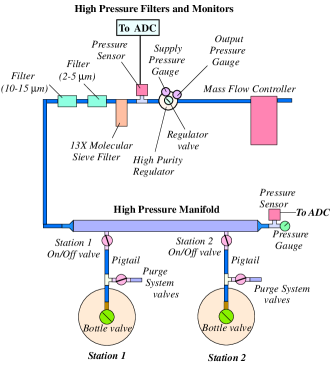
In addition to the low-pressure scrubber system, we installed a high pressure filtration system directly on the ethane bottles to remove oil, water, and possible large debris upstream of the high-pressure regulators. The system was composed of a pair of mechanical filters effective at eliminating contaminants greater than 10-15 and 2-5 microns respectively, available from many sources in varying form [36]. The final stage of the high pressure filtration system was a type 13X molecular sieve [37], a crystaline metal aluminosilicate. This type of sieve material is composed of Na2O, Al2O3, and SiO2. It is capable of removing H20, CO2, H2S, oil, and metacaptans (compounds with an alcohol-like structure, with the OH radical replaced by an SH radical). The nominal pore diameter is 10 Å, and expected levels of H2S after this high pressure system were below 0.1 ppm.
4.4 Flow control
Drift gas mixtures and flow rates were controlled by a Matheson Multichannel Dyna-Blender [38]. Each channel was a mass flow controller that delivered the appropriate flow near atmospheric pressure, regardless of the input pressure. The blender maintained gas mixture ratios to 2% precision at operational flow rates, and adjusted as necessary for fluctuations in input pressure. It simultaneously provided online flow readings, so it also served as an indicator of gas-supply shortages.
Total helium flow to the volumes surrounding the straws was controlled by a dependent channel of the blender. This channel was maintained at some fraction of the flow rate of the total internal straw flow, thus limiting the differential pressure experienced by the straws.
The blender regulated the total flow of the gas mixture and the helium. Distribution of the gas to the 8 detectors (14 modules) was accomplished by a parallel set of rotameters. Vent bubblers were used to prevent contamination of the gas volume from back flow and maintained a minimum pressure inside the chamber. Differential pressure sensors [39] monitored the difference in pressure between the drift gas and surrounding helium volume at each chamber.
4.5 Helium volumes
To minimize multiple scattering, polyurethane bags filled with helium surrounded the whole detector, filling the spectrometer fiducial volume. Helium also filled the volumes made up by chamber frames, outside the straws. The gas system was tuned to maintain a positive outward pressure gradient on the straw tube walls. Higher pressure was needed on the inner surface since the straw tubes were very sensitive to outside forces that were not compensated from the inside. Lab tests had shown that straws could withstand at least 20 psig of inner pressure without any damage. On the other hand, the smallest pressure on the outside surface deformed them. If this deformation was more than 1-2 cm long, the cathode did not return to its original shape; the resulting defect could thus distort the straw electric field. Helium was flowed through the volumes rather than statically filling them, to prevent the potential accumulation of flammable gasses.
As a final precaution, a set of differential pressure sensors were installed. They continuously measured the differential pressure between the inside and the outside of the straws. A pressure threshold of 2.54 cm of water was used to generate an alarm. Readings of the differential pressures were displayed online in the control room.
The helium supplied to the helium bags surrounding the chambers was independent from the helium supply inside. A system of photohelic gauges monitored the differential pressure of the inside and the outside of the bags. Their mission was to automatically switch on and off actuator valves so that the bags were always full. If the pressure had exceeded a prespecified pressure level, then the bag would start pushing the thin Mylar windows enclosing the chambers’ helium volume. The bags would have effectively applied an increased pressure on the outside of the straw tubes. Relief valves (bubblers) were placed at the output of the helium bags to protect the chambers in case of failure of the photohelic system.

4.6 Operating conditions
| Station | ||||
|---|---|---|---|---|
| 1 | 2 | 3 | 4 | |
| height (in) | 24.077 | 34.472 | 54.904 | 57.688 |
| width (in) | 8.600 | 8.600 | 8.600 | 8.600 |
| length (in) | 37.075 | 37.775 | 40.282 | 38.740 |
| volume (L) | 125.8 | 183.5 | 311.7 | 314.95 |
| Station | ||||
|---|---|---|---|---|
| view | 1 | 2 | 3 | 4 |
| length (cm) | 80.36 | 89.40 | 113.97 | 119.67 |
| No. straws | 513 | 516 | 550 | 531 |
| volume (L) | 8.11 | 9.07 | 12.32 | 12.07 |
| view | 1 | 2 | 3 | 4 |
| length (cm) | 88.88 | 89.03 | na | 91.85 |
| No. straws | 309 | 344 | na | 463 |
| volume (L) | 5.40 | 6.02 | na | 8.36 |
Keeping down the cost of our supply meant restricting the flow of our gas mixture to the lowest safe value. Due to its small molecular size, helium could invade the straw volume through the straw walls, affecting mixture purity. In addition, electron impact dissociation in the gas produces F- and CF negative ions together with F∗, CF and CF radicals. Too little flow would have allowed these radicals enough time to become involved in polymerization and further chemical reactions, including etching. The copper layer is extremely volatile to fluorine or hydrogen fluoride (HF) under the proper conditions as a non-dry environment.
During the first running period of the experiment, the flow was set to 3-5 volume exchanges per day. Lab tests had shown no problems with this flow rate. However, these had been performed outside of the intense radiation environment of the E871 spectrometer, and not for such long periods. As has been discussed, we eventually discovered signs of etching in the most heavily radiated straws. For the 1995 run period the flow was increased to 8-10 volume exchanges per day, freezing visible etching effects. In the new set of chamber modules used in the 5-month 1996 run period, we observed no etching effects with this higher flow rate.
4.7 Running experience
The gas system operated successfully, providing the necessary purity of gases while maintaining a constant flow and mixture ratio. No sulfur contamination was detected and no aging effects were observed in the performance of the detector. No further evidence of aging was observed after the flow rate increase and installation of the scrubbing systems.
During the 12 months of operation the PURASPEC 4037 material had slightly changed color, indicative of sulfur trapping, while the silica gel was twice overloaded with water. The NANOCHEM oxygen cartridge was very sensitive, easily overloaded with oxygen in open air contact, and without self-indication. We replaced it on a regular schedule (after every second cylinder of used), but the system was always vulnerable to contamination from insufficient purging upstream or from any leakage downstream.
The differential pressure sensors proved to be extremely useful. With gas lines of tens of meters lengths and numerous connections, valves and distribution manifolds, it was easy to limit by accident either the input or the output flow of the gas mixture. At least twice they provided critical alarms of higher pressure on the outside helium volume. The pressure was sensed through long lines since the actual sensors were located far away from the detectors (outside the high radiation area). This caused a delay in measuring the actual pressure gradient.
The use of manifolds with multiple stations, double filtering systems and purging capabilities, allowed the continuous and uninterrupted flow of gas for long periods (6 months). The pressure and flow sensors provided warnings for each irregularity in the normal operation and reminders for the necessary maintenance of the system. The precision of each gas component flow was 10 ccm, resulting in a 5% uncertainty in the mixture ratio at the operational flow. The distribution of flow to individual modules was done with flowmeters with flow adjusting valves. These provided only a rough measurement of the portion of the total flow directed to each module. They were unreliable and two of them had to be replaced because of malfunction. Also, the Matheson high pressure sensors had a high rate of failure; two stopped working after months of normal operation.
5 Performance
5.1 Chamber calibration
5.1.1 Alignment
The straw chambers were installed in the E871 spectrometer on tables of aluminum jig plate, which had been surveyed relative to the beam axis and target. The chambers were pinned and bolted to the tables before they themselves were surveyed. Much more accurate relative positions information could be obtained using track data recorded with the spectrometer magnets off. Corrections to the optical survey results were derived from this straight-through data.
Relative transverse corrections to chamber positions within a view ( or , left or right) can be readily extracted from straight-through tracks, but longitudinal (beam parallel) and global corrections require more work. The relative positions of the left and right arms of the spectrometer were extracted from reconstructed vertex distributions, while longitudinal corrections within spectrometer arms were derived from magnet-on data, where allowances for multiple scattering in the track fitting algorithm had been disabled in software.
Alignment was performed iteratively. The tracking , measured with an independent fitting algorithm, reduced systematic errors from the combined effect of the magnetic field map and the spectrometer survey to below 1%.
5.1.2 Timing and drift velocity
For every change in straw and drift chamber operating conditions, we generated new calibrations for TDC time offsets, single-wire efficiencies, and effective time-to-distance relations. More than sixty calibration updates were needed for the two years’ run periods.
Normal minimum-bias data and random-trigger data were used to perform the calibrations, which were done in an iterative fashion. Noise rates determined hot or dead wires, while time sum residuals between neighboring wire pairs were minimized to determine the TDC time offsets.
5.2 Straw system performance


As shown in Figure 17, noise rates for individual wires in the straw chambers approached 750 kHz at 15 protons (Tp) on target for wires near the beam and in front of the beam stop. The continuous cathodes and stability of the straws allowed smaller cell size for decreased occupancy, while minimizing crosstalk. A typical residual distribution is shown in Figure 18. The mass resolution of the spectrometer as a whole is shown in Figure 19, which shows a mass peak with a mass resolution of 1.11.


Straw efficiency was flat across most of the cell area, dropping off near the straw wall, where particles traversed increasingly smaller gas path lengths. The flatness of the efficiency as a function of wire number (and thus position) for the most upstream chamber (for example), shown in Figure 20, clearly displays the stability of the E871 straw chambers regardless of occupancy, since, as evident from Figure 17, the upstream chamber intensity varies across the chamber face. Figure 21 displays the single-channel efficiencies for all straw and conventional drift chambers. The mean efficiencies for straws and drift chambers were 96% and 98%, respectively.
6 Summary
We successfully developed, built, and operated a set of straw tracking chambers with over 6500 channels for the BNL E871 rare decay search. The system proved to be robust, with no rate-induced tripping or inefficiency at rates over 700 KHz. The system utilized a close-pack cell configuration of Mylar or Kapton 0.5-cm diameter, copper-lined straws with a 50:50 - drift gas at atmospheric pressure. We developed custom front-end amplifiers and electronics for the chambers, and operated them for two years’ running periods at Brookhaven National Laboratory.
References
- [1] D. Ambrose et al.(BNL E871 Collaboration), Phys. Rev. Let. 81 (1998) 5734.
- [2] D. Ambrose et al.(BNL E871 Collaboration), Phys. Rev. Let. 81 (1998) 4309.
- [3] D. Ambrose et al.(BNL E871 Collaboration), Phys. Rev. Let. (in preparation).
- [4] S. Worm, Ph. D. Thesis, University of Texas, Austin, June, 1995.
- [5] J. Belz et al., Nucl. Inst. Met. (submitted, e-print hep-ex/9808037).
- [6] M. Frautschi et al.(AMY Collaboration), Nucl. Inst. Met. A307 (1991) 52-62.
- [7] A. Tomasch et al., in Adelaide 1990, Proceedings, Cosmic ray, vol. 4* 414-417.
- [8] Bing Zhou et al., IEEE Trans. Nucl. Sci. 37, 1564 (1990). V. Bondarenko et al., Nucl. Instrum. Meth. A 327, 386 (1993). V. Commishau et al., CERN-DRDC-93-46. T. Akesson et al., Nucl. Instrum. Meth. A 361, 440 (1995). T. Akesson et al. [ATLAS-TRT Collaboration], Nucl. Instrum. Meth. A 449, 446 (2000).
- [9] Y. S. (Paul) Tsai, Rev. Mod. Phy. 46 (1974) 815.
- [10] Mylar is DuPont Corporation’s brand name of a polyester film.
- [11] Kapton is DuPont Corporation’s brand name of a polyimide film.
- [12] T.S. Shin et al., Nucl. Inst. Met. A332 (1993) 469.
- [13] The Mylar straws for 1995 were wound by Stone Industrial, 9207 51st Ave., College Park, MD 20740-1910, (301)474-3100.
- [14] The Kapton straws straws for 1996 were wound by Lamina Dielectrics Ltd., Myrtle Lane, Billingshurst, West Sussex, RH14 9SG, UK, +44 1403 783131.
- [15] 20, gold-plated tungsten wire supplied by SAES Getters, 1122 E. Cheyenne Mtn. Blvd., Colorado Springs, CO 80906, (719)576-3200.
- [16] The vapor-deposited Mylar and Kapton was supplied by Sheldahl Corp. P.O. Box 170, Northfield, MN 55057, (507)663-8000.
- [17] Ultem 1000 is a registered trademark name for polyetherimide resin by General Electric Company. Ours was supplied by Polymerland, 500 Park Blvd., Suite 245, Itasca, IL 60143, (800)752-7842.
- [18] Tyvek is a product of DuPont Corporation.
- [19] K. McDonald et al., Princeton University, private communication.
- [20] Feedthrough molding by Advance Tool and Die, 226 Highland Ave., Westmont, NJ 08108, (609)854-6329.
- [21] Brass sleeves and pins machined by J&J Swiss Precision, Inc., 160 West Industry Court, Deer Park, NY 11729, (516)243-5584.
- [22] Frames machined by Brigg’s Machining Co., 23190 Del Lago, Laguna Hills, CA 92653, (714)770-1160.
- [23] EPO-TEK 301-2, EPO-TEK 110, and EPO-TEK 410E were supplied by Epoxy Technology Inc., 14 Fortune Dr., Billerica, MA 01821, (508)667-3805.
- [24] Tra-Bond 2143D supplied by Tra-Con, Inc., 55 North St., Medford, MA 02155.
- [25] Dow 3110-RTV by Dow Corning, Midland, MI 48640, (800)248-2481.
- [26] EFD Dispensing Components, 977 Waterman Ave., East Providence, RI 02914, (800)828-3331.
- [27] M. Hamela and P. Yager, private communication.
- [28] K. Lang, J. Ting, and V. Vassilakopoulos, Nucl. Inst. Met. A420 (1999) 392.
- [29] S. Graessle et al., Nucl. Inst. Met. A137 (1995) 138.
- [30] A. P. Heinson and D. Rowe, Nucl. Inst. Met. A321 (1992) 165.
- [31] The U.S. representative for ICI Catalysts was ICI Katalco, Two Trans Am Plaza Dr., Suite 230, Oakbrook Terrace, IL 60181, (708) 268-6300.
- [32] Oxygen trap with replaceable cartidge, Scott Specialty Gases, Part no. 53-42CT. Each catridge will remove 99% of the oxygen present in a gas stream with a 15ppm O2 level. Its capacity is 127 ml of O2 at 99% efficiency.
- [33] R. D. Cousins, C. Friedman and P. L. Melese, IEEE Trans. Nucl. Sci. 36, 646 (1989). R. D. Cousins et al., Nucl. Instrum. Meth. A 277, 517 (1989).
- [34] J. Vavra, Nucl. Instrum. Meth. A252, 547 (1986).
- [35] J. Vavra, P.A. Coyle, J.A. Kadyk and J. Wise, Nucl. Instrum. Meth. A324, 113 (1993).
- [36] High pressure gas filter, Scott Specialty Gases Part no. 53-45F-111 (53-45F-112) or Hoke Part No. 6321F4B (6323F4B). Max pressure 3000 psi, removes particles larger than 2-5 (10-15) microns.
- [37] High Pressure filter, Scott Specialty Gases, Part no. 53-43H, Max. Pressure 3000 psig. Brass with Viton O-ring. Active purifier element: Molecular sieve 13X (Part no. 53-43E); removes oil, water and particulates.
- [38] Our gas flow controller console was the Matheson Dynamic Gas Blending System Series 8284 Dyna-Blender, a system equipped with four independent transducers/controllers, Matheson Part No. 8272-0413,-0424. They were calibrated for , , isobutane, and Helium with input pressure of 20 psig and atmospheric output pressure.
- [39] Pressure Transducers, Matheson part No. 8816 (Range 0-3000 psia).
- [40] Dual Stage High Purity Brass Regulator, Matheson Model 3120 Series, with Teflon seats. It was used for , Ar gases. Matheson Model 3100 Series was used for hydrocarbons.