The Architecture of the ZEUS Micro Vertex Detector DAQ and Second Level Global Track Trigger
Abstract
The architecture of the ZEUS Micro Vertex Detector data acquisition system and the implementation of its second level trigger, the ZEUS Global Track Trigger are described. Data from the vertex detectors HELIX read-out chips, corresponding to 200k channels, are digitized by 3 crates of ADCs which perform noise and pedestal subtraction, and data suppression and compaction. PowerPC VME board computers push cluster data for second level trigger processing and strip data for event building via Fast and Gigabit Ethernet network connections. Additional tracking information from the central tracking chamber and the forward straw tube tracker are interfaced into the 12 dual CPU PC farm of the Global Track Trigger where track and vertex finding is performed. The system is data driven at the ZEUS first level trigger rate ( 500Hz) and must generate a trigger result after a mean time of 10ms.
I Introduction
The ZEUS detector at DESY is designed to study high energy interactions produced at the HERA collider. In the period 2000-2001, the 920 GeV proton - 27 GeV electron collider underwent a substantial upgrade aimed at increasing by a factor 5 the peak luminosity, corresponding to 200 pb-1 integrated luminosity per year. During the upgrade shutdown, ZEUS has been equipped with a silicon vertex detector which, besides a general improvement and extension of the track reconstruction, will enhance the identification of short lived particles.
This paper describes in sections 1-8 the hardware architecture of the Data Acquisition system and the embedded Global Tracking Trigger (GTT). Section 9-11 outline the software solution used. Section 12 describes the trigger algorithm. Performance and Outlook are reviewed in sections 13 and 14.
II Detector Layout
The Micro Vertex Detector (MVD) consists of a barrel section with three double layers of silicon sensors surrounding the beampipe and four wheels in the forward, outgoing proton, direction. Longitudinal and transversal views of the detector with respect to the beam line are shown in Fig. 1.
The sensors are single sided and made of high-resistivity ( k cm) 320 m thick n-type silicon into which strips, 12 m wide and with a 20 m pitch, are implanted. The signal is read out via AC coupling of 14 m strips placed at a pitch of 120 m. The rear side consists of a thick diffusion. Test beam results have shown that, using capacitive charge sharing, a resolution up to 8 m can be obtained for tracks perpendicular to the sensor.
In the barrel region two consecutive sensors of square shape ( mm), with orthogonal strips, are glued and electrically connected together via a copper trace etched on 50 m thick Upilex foil. The connection of the sensor assembly to the read-out hybrid also uses Upilex foil. This structure with a mirror one having perpendicular strip orientation forms a barrel module with 2048 read-out strips or 1024 channels. Five modules are mounted on a carbon fiber ladder that provides the required stiffness and support for the cooling pipes, cabling and slow control sensors.
The forward section consists of four wheels, each made of two parallel layers of 14 silicon sensors of same type as the barrel section but with a trapezoidal shape and 480 read-out channels. Two sensors mounted behind each other form a forward segment and provide a two coordinate measurement via strips tilted by in opposite directions. A more detailed description of the detector layout and of the silicon sensors can be found in layout .


 Forward MVD
Barrel MVD
Forward MVD
Barrel MVD
III The MVD Front-end and Read-out Electronics
The read-out of the 207,360 channels is performed by the HELIX 128-3.0 front-end chip helix , a 0.8 m CMOS chip specifically designed for the HERA environment. Each of the 128 channels is equipped with a preamplifier, a shaper and an analog 136 step analog pipeline. A pipeline read-out amplifier, a 40 MHz multiplexer and a 40 MHz current buffer form the backend stage of the design. The noise performance of the chip depends on the input capacitance (C) and is C [pF] equivalent noise charge (ENC). The bias settings and various other parameters of the analog read-out can be finely adjusted to optimize the system to the detector input characteristics and correct for radiation damage effects. Irradiation tests of the HELIX read-out have been performed and indicate that a total dose of 300 kRads can be received before degrading the performance. The anticipated dose of 10-20 kRads per year at HERA will allow more than the 5 years of operation foreseen.
During operation the power dissipation of the HELIX is 2mW per channel while the power dissipation in the silicon sensors is negligible.
The bias setting and register programming as well as the clock, trigger and test pulse synchronization, are performed via a serial interface driven by custom designed 6U VME driver boards. Eight chips belonging to the same barrel module or the same forward segment are connected together in a programmable failsafe token ring111 By providing 2 inputs and 2 output connection lines from each chip to its neighbours, the failsafe token ring, allows any subchain with not more than one consecutive faulty chips to be read out. This reduces the impact of faulty chips on the number of channels read out per chain. and read out via a single digitization channel.
The analog serialized output data are sent through passive copper links to dedicated 10 bit ADC VME embedded modules adcm . At the input to the ADC module the signal range is 0-2V corresponding to 0-10 minimum ionizing particle. The ADC system performs common mode noise and pedestal subtraction and writes data into strip or cluster cyclic event data buffers. The strip buffer contains either raw or strip data where an energy threshold cut is applied. The cluster buffer contains information from groups of contiguous strips (center value, total energy, first and last strips, etc.); a cut can be applied on the total energy and dead or hot channels can be masked. Cluster data is used for triggering purposes and strip/raw data for event builder read-out. The ADC system has been implemented as a 9U single width VME board each with 8 analogue inputs. The total of 206 tokens are distributed in three VME crates: upper-barrel, lower-barrel and wheels.
The HELIX front-end and ADCs are controlled by the clock-and-control system. This consists of a single master with three ADC crate slaves and the HELIX-driver system. The clock-and-control system provides the interfaces between the ZEUS Global First Level Trigger (GFLT), the run control system, the ADC crates and the front-end chips. The HELIX-driver boards are used by the run control to configure the system and by the master to propagate trigger accepts to the HELIX which outputs the analogue signal with its own scheduling after receiving the trigger. The system is free running, the ADC modules inhibiting the trigger (busy) when the data buffer full condition occurs. The ADC system performs several checks to ensure correct event processing. The length of the input data is checked for its correspondence to the configured number of data strips expected. The cell number is decoded from trailer data to identify pipeline jumps. Data arrival times are measured with respect to the trigger timing. Error conditions are written into the output buffers and fatal errors can assert a master error blocking the trigger.
The ADC read-out is performed via VME PowerPC boards running LynxOS 3.01 and a dedicated software library uvmelib . The decision to use Motorola PowerPC read-out CPUs was made in 1999 after feasibility studies on the VME and network data transfer bandwidth and latency measurements. The use of LynxOS, at that time, was essential as it provided a UNIX environment with a realtime kernel. Priority scheduling of the interrupt handling, VME data read-out via independent DMA and network transfer task pipeline were required to reach the necessary performance.
IV The ZEUS Data Acquisition System
The ZEUS data acquisition system zeus93 is based on a three level trigger. Because of the HERA bunch crossing rate of 10.4 MHz, i.e. 96 ns between consecutive interactions, the experiment is required to use a pipelined read-out design. The GFLT, based on a reduced set of information from the detector components, is issued after 46 bunch crossings and reduces the trigger rate to Hz. Detector data, stored in deadtime-free analog or digital pipelines, is subsequently digitized, buffered and used by the Global Second Level Trigger (GSLT). The GSLT lowers the trigger rate to 70 Hz with a typical latency of 10-15 ms. For accepted events the complete detector information is read out, merged with the other detector components data by the Event Builder (EVB) and sent to the Third Level Trigger (TLT) computer farm where event reconstruction and final online selection are performed. In normal data taking conditions the system runs with a deadtime %.
V The Global Tracking Trigger
The architecture of the MVD DAQ has been strongly influenced by the development of its contribution to the ZEUS trigger. As the HELIX front-end and ADC read-out is too slow to participate to the First Level Trigger a contribution at the second level was targeted.
Simulation studies on data multiplicity and background have shown that the MVD data alone, providing up to 3 planes of information per track would not be sufficient for unambiguous tracking and efficient rate reduction. Combining MVD information with the surrounding tracking detectors allowed a far better rate reduction and tracking efficiency. These considerations have lead to the design of the new Global Track Trigger, a distributed computing environment processing data from MVD, the existing Central Tracking Detector (CTD) and the newly installed forward Straw Tube Tracker (STT).
The CTD ctd is a cylindrical drift chamber surrounding the MVD and covering the polar angle range . It consists of 72 radial layers grouped into 9 superlayers: the odd superlayers have axial wires parallel to the beam axis while the even superlayers have small angle stereo wires allowing determination of the position of hits. The three inner axial layers are also equipped with -by-timing electronics which determine the -position of a hit from the difference in arrival times of a pulse at both ends of the chamber.
The STT stt consists of 4 superlayers of straw drift tubes of 7.75 mm inner diameter covering the polar angle . Each superlayer contains 2 planes composed of 6 trapezoidal shape sectors covering the full azimuthal angle. A sector consists of 3 vertical layers of straw tubes oriented in the azimuthal direction and providing an accurate measurement of the radial coordinate of the tracks. The STT superlayers are hosted in groups of two between plane 1 and 2 and plane 3 and 4 of the existing ZEUS Transition Radiation Detector.
In the design of the DAQ and GTT system, the preferred choice has been to use, whenever possible, commercial off the shelf equipment easily upgradeable and maintainable. After investigation of the performance achievable in terms of data throughput, process latency and performance, a solution based on a farm of standard PCs connected via a Fast/Gigabit Ethernet network has been chosen.
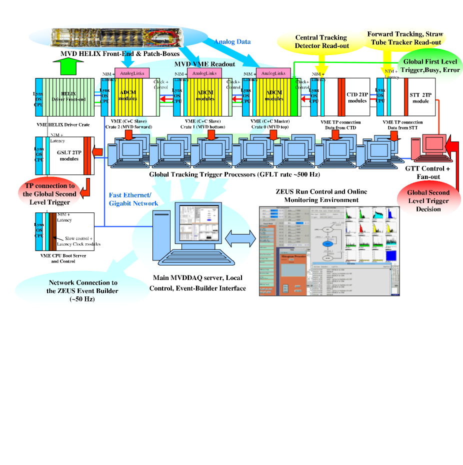
The final hardware implementation of the MVD DAQ and the GTT systems is shown in Fig.2. In table 1 the hardware characteristics are listed.
On GFLT accept data is transferred from the silicon detector HELIX read-out chip pipelines to 30 ADC boards where data is digitized and stored in strip and cluster FIFO buffers. On completion of digitization a VME interrupt is generated and the cluster data is read out, via VMEbus, by a read-out CPU (Motorola MVME 2400 PowerPC/LynxOS) and sent to a GTT reconstruction environment. The GTT result is then forwarded to the GSLT interface hosted in another VME system. If the event is accepted at GSLT the complete read-out of the strip/raw data from the 3 MVD crates together with the complete GTT output is sent to the event building process.
VI The CTD and STT Interfaces
The CTD and STT DAQ systems, as many other component in the ZEUS experiment, are based on transputers 222INMOS Transputers, were an advanced technological development in the early 90’s when the ZEUS experiment was designed. Provided with a 32 bit processing unit, on board memory, four 20 MHz serial links for processor interconnection and a high level parallel programming language (OCCAM), transputers were ideal for highly distributed parallel processing and data transfer.. In order to connect these component to the GTT, the existing transputer networks had to be extended and an interface from the transputer protocol to the plain Ethernet network was required. At the time of design no commercial solution with the required flexibility and bandwidth was available; a VMEbus system based on the same read-out CPUs used in the MVD was commissioned ctdint . As shown in Fig. 2 a Motorola LynxOS board gathers data through the VMEbus from NIKHEF 2TP modules 2tp , each module consisting of 2 transputers and a shared triple port memory and providing up to 8 transputer links. Data are collected by the CPU, merged event by event and sent through Fast Ethernet to the GTT environment.
On GFLT accept digitized pulse height and drift time data from the 4608 CTD sense wires are read out from custom FADC cards by 16 sector read-out transputers. To enable the data from the CTD to be used at the GTT 16 additional data splitting TPs were added to the CTD DAQ. These allow data from the FADC system to be parasitically read out from the network whilst causing minimal disruption to the data flow within the CTD network.
The STT, installed in 2001 and recommissioned in 2003, replace the Transition Radiation Detector (TRD) and has been designed to reuse the existing TP based read-out system which is similar in design to that of the CTD, using the same custom FADC and TP electronics. The STT interface to the GTT is implemented using the system developed for the CTD, although only 8 input TP links (one 2TP module instead of two) are used. The STT frontend electronics digitise hits above threshold and only drift time information is available to the GTT. The expected STT data volume per GFLT accept is 4kB with a read-out latency similar to that of the CTD. At the time of writing the STT interface to the GTT is fully operational although data was not transferred during luminosity running to the GTT.
| Number | Item | Purpose |
|---|---|---|
| 1 | DELL PowerEdge 6450 Quad 700MHz 1GB | NFS File Server, EVB Interface and Run Control |
| 1 | DELL PowerEdge 4400 Dual 1GHz 256MB | GTT Server+Credit/GSLT Decision |
| 12 | DELL PowerEdge 4400 Dual 1GHz 256MB | GTT Algorithm Processing |
| 5 | Motorola MVME2400 450MHz 64MB | MVD Read-out, CTD and STT Interfaces |
| 1 | Motorola MVME2700 367MHz 64MB | GTT to GSLT Trigger Result Interface |
| 1 | Motorola MVME2700 367MHz 64MB | LynxOS Boot Server and Development Node |
| 4 | NIKHEF-2TP VME-Transputer modules | Transputer Protocol Conversion |
| 1 | Motorola MVME2700 367MHz 64MB | HELIX Programming CPU |
| 2 | Intel Express 480T Fast/Giga-16Port Cu Switch | Network Connections |
VII The GTT Environment Process
The GTT as any of the components participating to the ZEUS second level trigger has to process events at the average rate Hz with a mean latency, including all the data transfers, of less than 10 ms and possibly small tails due to busy events or performance fluctuations.
Studies of the network throughput using commercial PCs and LynxOS PPC boards, indicated, after proper tuning of TCP socket options, Fast and Gigabit Ethernet to be a reliable low and stable latency connection. Feasibility tests using a single data source feeding 4 PCs running dummy GTT algorithms on a round-robin basis were made with the data being immediately forwarded to a dummy GSLT trigger sink. The results in terms of rate and latency indicated the use of TCP/IP and Fast Ethernet as acceptable. Additionally a port of the CTD-SLT TP code to a single CPU showed that processing speed was sufficient on PCs to satisfy the requirementsgtt .
In the current system all MVD DAQ and GTT components are connected using the TCP/IP protocol via point-to-point Fast and Gigabit Ethernet links to network switches.
The GTT environment process is a multi-threaded program with one thread per input data source (MVD, CTD, STT), one thread per trigger algorithm and a time limit thread.
Typically one environment runs on each of the 12 dual CPU farm PCs. The location of the next environment to receive event data is stored in a synchronized ordered list at the data interfaces. When available the environment sends its credit to the data source processes. The decision to use credits to control availability rather than round-robin distribution was determined from simulation studies.
For development and performance tests a playback capability has been provided: upon a First Level Trigger the component front-end electronics is read out and Monte Carlo or previously saved events stored in memory are injected into the GTT trigger chain at the component VME interfaces, and sent through the system exactly as for regular data.
Currently a barrel algorithm using CTD+MVD data is implemented. A forward algorithm, using STT+MVD is in preparation.
VIII GSLT and EVB Interfaces
As the GSLT is based on a transputer network a similar solution as for the CTD and the STT was commissioned. The GTT result, is sent to a Motorola PowerPC VME CPU which transfers the result, via a 2TP module and one of its TP serial links, to the GSLT. As the order of the GFLT number of the trigger results arriving at the GSLT is strictly sequential the interface is required to order the results from the different GTTs before sending.
No special hardware is required to receive the GSLT trigger decision as this is transferred via TCP. An interface process forwards it to the MVD data sources and GTT environment which processed the event. On accept the data sources send MVD strip data and the environment sends MVD cluster and algorithm calculation details to the EVB interface.
The EVB interface waits for MVD and GTT data associated with GSLT accepted events which are merged, formatted into the final ZEBRA and ADAMO banks and sent to the EVB via TCP/IP. A complete data quality monitor is performed on this system.
IX The VMEbus Access Implementation
A software package for VMEbus access on Motorola PPC boards running LynxOS has been developed. This package exploits the features of the hardware and the operating system to provide flexible VME memory mapping, DMA transfer, VME interrupt and process synchronization control in a multiuser environment. The package consists of a library named UVMElib uvmelib layered on an enhanced driver for the Tundra Universe II chip with respect to the default version distributed by LynxOS. The user performs all VME and related operations by using the library without any direct connection to the driver. Within the library, the basic data structure type handled by the user to describe Shared Memory Segments opened both on the internal PCI DRAM and/or on the VMEbus has six fields: an id, an ASCII name, a size (in bytes) an addressing mode and a virtual and physical address, corresponding to the address the application has to use respectively for normal read-write cycles and DMA operations. For simplicity both internal contiguous DRAM segments and VME ones are allocated in the same way. Standard API are provided to support process synchronization by waiting on or setting system semaphores. It is possible to connect VME interrupt handling to some UVME semaphores, making synchronization to hardware interrupts, DMA cycles or software signals equivalent. It is worth noting that segments are uniquely identified by id or name. This allows many processes to connect to already existing mapped regions (up to eight for the VME space) without overloading the system.
X The VMEbus Read-out Software
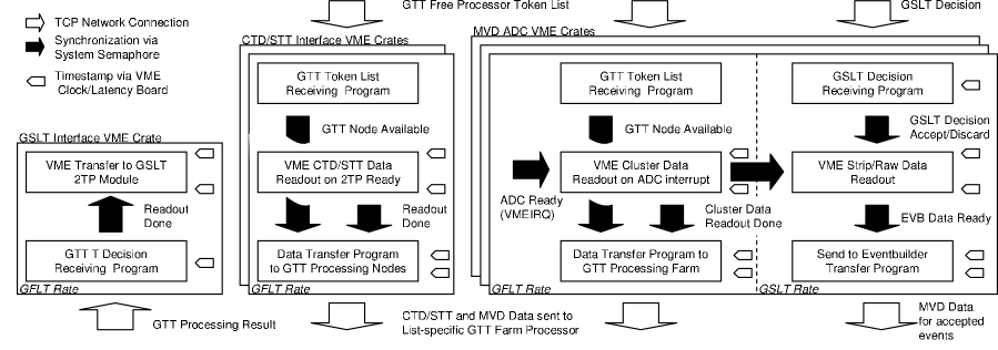
The MVD read-out software, due to the strict requirements imposed by the participation to the second level trigger, has required careful design: the DMA transfer and the VME mapping capabilities of the Universe II bridge together with LynxOS specific mapping of contiguous shared memories, use of system semaphores and flexible priority scheduling have allowed a modular design of the complex DAQ environment. A diagram of the main processes running on the VME computers when taking data is shown in Fig. 3
On the ADC systems two software pipelines running at FLT and SLT rates exist. At FLT rate the read-out program running at lower priority, is woken up on VME interrupt as soon as data are ready on the ADC boards. After data has been transferred via DMA to internal memory, the network tasks, synchonized by a semaphore and running at a higher priority, will send the data to the GTT farm. The machine destination list is independently updated by a network receiving task driven by the GTT process sending its credit. A similar software pipeline is available also on the CTD and STT interfaces although currently since the 2TP modules cannot generate a VMEbus interrupt, the PowerPC polls for data every 500s.
After the GTT processing the trigger result is sent to the GSLT and the list of the idle processors is updated.
All data transfers are performed using standard TCP protocol. To cope with the different platforms involved (PowerPC for the VME read-out and standard PC for the DAQ and GTT computing nodes) the communication and synchronization is done via short XDR encoded messages while detector data is sent with no additional overhead.
To precisely monitor read-out latencies and network transfer times an all purpose 6U VME board vmeallp , providing among other features a latency/clock register, has been developed and installed in all VME crates and connected to a common 16 clock bus.
Absolute timestamps and latency measurements are available for every event and stored in the data at several points of the data acquisition phase allowing a complete understanding of the system performance.
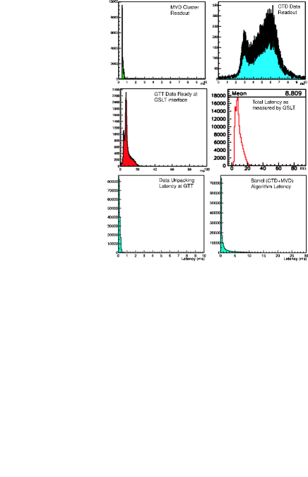
In Fig. 4 the latency distributions for the cluster read-out, the CTD data read-out, the algorithm processing and the total GTT system latency are shown for a typical luminosity run from 2003. A mean value smaller than 10 ms with steep tail, compatible with the initial requirements is obtained. The data unpacking and algorithm processing latencies for the same run are also shown. The distribution is monotonically falling, since the algorithm runs as a single process, and has a mean of 1.4 ms with a tail extending to around 15 ms for busy events. A significant contribution to the total latency results from the latency of the CTD transputer network in providing data to the CTD interface. This time is not completely wasted as it is used to transfer and unpack the MVD data, usually available much earlier. For the same run, the average number of credits, i.e. the number of GTT idle processors, was 9 with a lower tail of less then 5 occurring for less that 1% of the events. This indicates the current farm with 12 GTT nodes as more than adequate for the present GFLT rate and total latencies.
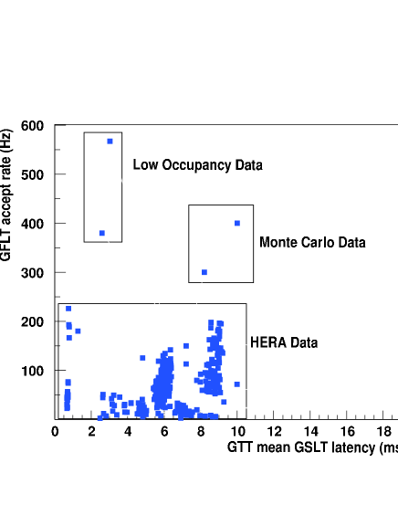
In Fig. 5 the GTT total latency versus the GFLT rate is shown. The dependence of the mean overall latency on the output rate of the GFLT, typically between 50 and 200Hz during this data taking period, shows a strong dependence on the background conditions, but always lies within 10ms.
Typical data sizes were 5 kB, 15 kB and 45 kB for CTD, MVD cluster and MVD strip total data.
Studies using the playback system, suggest that operating the GTT with GFLT output rates of up to 500Hz is achievable.
XI Computing Environment and Software
As already described, the DAQ computing environment consists of VME boards computers running LynxOS and Intel PCs running Linux interconnected via point-to-point Fast or Gigabit Ethernet via network switches. The VME systems are diskless and are booted over the network from a single, dedicated, VME system acting as a boot server. All Linux systems are booted from local disk. In order to simplify code usage a single DAQ file system, containing executable directories etc., is mounted via NFS by all participating hosts.
Standard C programming has been used throughout the DAQ and GTT systems. A number of ROOT based C++ GUIs have been developed to control the DAQ system in standalone mode, view online or archived histograms, control manually the detector slow control system, etc.
All non read-out or trigger data messages are transmitted through a hub process and not directly between processes. The hub is a multi-threaded processes which accepts connections at a known address and enforces a simple protocol, using XDR, which allow connecting processes to define themselves with known ’public’ names or remain anonymous and set up or cancel forwarding requests. Forwarding is based on public name, XDR union tag and a 128 bit MD5 hash field (matches can be made less specific with * wildcards with the public name to select groups or all names, and 0 when used with tag and hash fields which enables all matches).
The hub has a number of other useful features including retension of the most recent message based on name-tag-hash. The principle reason for implementing the hub was to reduce programming complexity in the MVD environment where many monitoring and logging tasks are running. There are, of course, many tasks running in the system which do not require network communication.
XI.1 Run and Process Control
The MVD run control can run in either standalone mode or as part of the ZEUS run control system. In both cases process control, stopping and starting tasks, is facilitated by daemon processes started at boot time. These advertise themselves to the run control system and identify, by name, what processes they are capable of running, usually this is host specific. Run configuration requests from ZEUS or the standalone run control specify a Runtype definition file naming all the processes to be started of stopped, the parameters they require, their required exit status etc. The C preprocessor (cpp) is then invoked to expand all of the definitions contained in the file (resolving required processes, their supporting daemon, startup parameters, etc.). The file produced corresponds to a sequential list of process control commands required to perform all the transitions specified. Provided no error is encountered the run control system can then sequence all the steps required for each transition request received. Transition requests fail if any process fails to reach and remains in the required state.
XII The GTT Algorithm
The current implementation of the GTT algorithm, described in detail below relies heavily upon the existing CTD-SLT programctd and extends into the MVD barrel region. Unlike the CTD-SLT, it does not have access to the CTD -by-timing information and uses instead the data from the CTD stereo superlayers for reconstruction. The algorithm consists of four stages:
-
•
CTD segment finding,
-
•
- track finding (CTD tracks, MVD - hit matching),
-
•
-track finding (CTD stereo segment matching, MVD hit matching),
-
•
primary vertex identification.
A second pass through one or all stages is performed depending on the found tracks and primary vertex, thus improving secondary vertex finding.
The segment finder operates on both axial and stereo CTD cell data. To reduce the processing time, left-right ambiguities, introduced by the drift time information and providing real and ghost segment candidates, are removed by taking the segment pointing more closely to the beam line. This has a high efficiency for identifying high tracks, but leads to a charge asymmetry for lower tracks due to the asymmetry of the CTD geometry. In order to assign hits in a cell to a segment, starting from seed pair of hits, the algorithm looks for linear segments consisting of three or more hits, using a linear extrapolation to identify further hits on adjacent wires until either the cell boundary is reached or there are no more hits consistent with the segment. The segment finder stops looking for new segments in each cell as soon as at most four segments have been found. This limit is implemented since the time consumption is very sensitive to the detector occupancy, which is very high in non background events.
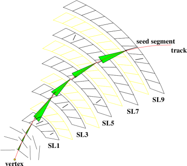
The - (axial) track finding, illustrated in Fig. 6, searches for tracks starting with a seed segment in the outer superlayer where the occupancy is lowest. Using this seed segment, the expected azimuthal position of the hit in the next innermost axial superlayer is calculated and segments consistent with this are matched to the track. The segment last matched is then used as a fresh seed and the matching proceeds again into the next inner axial superlayer until at least one segment is found in superlayer 1. Once the segment matching is complete, the track parameters are calculated assuming a circle in - using a fast circle fit constrained to the beam line to aid subsequent hit matching in the MVD. Since the MVD hits from both the - and sensors within an MVD half module are connected together, all hits must be considered as potential - hit candidates. Starting from the outermost MVD layer, the position for the track at the layer radius is calculated and ladders within a window of of this position are considered. All unmatched hits on these ladders are then considered, calculating the track at the radius of each hit. The closest hit on each possible ladder consistent with the track is then matched and the track recalculated with the MVD hits having a larger weight in the fit, allowing at most two hits per layer (one per ladder). The algorithm then proceeds in the next innermost MVD layer until all layers contain hits, or there are no further unmatched hits. When recalculating the track parameters for tracks with at least two MVD hits, the constraint that the track must come from the beam line is removed, in anticipation of secondary vertex finding and impact parameter calculation.
The stereo wire derived position position is only available when the - position of the hit on the track has been calculated. Since each stereo hit may be assigned to any track passing through the large range (4 cells) spanned by the wire, the - and positions of each hit must be calculated for each possible track candidate within its - range. For the innermost stereo layers, this range is up to , which presents a significant problem since the track occupancy nearer the interaction region is high and the degree of matching ambiguity which must be resolved is large.
The intersection of the track with the hit must be calculated considering the drift displacement of the hit with respect to the wire. This is done using an iterative algorithm vctrak and provides the position of the hit matched to the track, from which the wire position is obtained. The fraction of the length along the wire is then trivially extracted to provide the position of the hit.
Solving the track intersections in - with the stereo wires represents one of the most costly steps in terms of the processing latency. In order to keep the processing time within acceptable limits, as with the axial hit finding, segments are found in the stereo layers using the same algorithm as for the axial layers, with only the end points of the segments used for calculating the intersections in . This introduces some additional segment finding latency but significantly reduces the time consumption in the stereo matching.
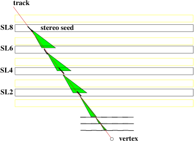
Since the ghost hits lie on the other side of the wire, matching to the track yields a similar hit position, but different wire position and thus a different position. The ambiguity is resolved by using the same beam line requirement as for the axial segments. Once the segments have been found, the stereo matching algorithm proceeds starting in the outer stereo superlayer for this track where the spatial separation of tracks is highest. All possible segments are considered as seed segments. The intersection of the segment end points with the track is calculated and fitted linearly in and , the transverse path length along the track, to provide a -track. The -track parameters are calculated and the track extrapolated into the next stereo layer. The positions of each segment in the next inner layer are then calculated by matching to the track as above. This continues in each successive stereo layer, with the fit being recalculated at each stage, until a track with segments in each stereo layer is found, or no matching segment is found. This is illustrated in Fig. 7. To improve the efficiency and resolution of track segment matching for events where more than a single segment candidate per cell exists, the algorithm makes additional passes to find the best candidate.
Once CTD stereo segments have been matched to an axial track, matching to MVD -hits is performed in a similar way as in the - case. Since MVD - positions are already known, the algorithm looks for unmatched hits only in the corresponding -sensors of the modules with - hits. Starting in the outermost MVD layer, if there are unmatched hits in the expected -sensor, the track intersection with the sensor is calculated. All unmatched hits are then compared with the predicted -position, and the closest hit consistent with the track is matched and the track recalculated using a higher weight for the MVD hit in the fit. The calculation of the track intersection and hit matching are then successively performed in the inner layers until either hits are found in all possible -sensors, or there are no hits remaining. The track-vertex and the weight from the fit are stored for use in the primary vertex fit.
The primary vertex algorithm is intended to make a fast estimation of the presence of a possible vertex and to ascertain it’s likely position in rather than a complete detailed reconstruction. The algorithm itself uses a binning algorithm with overlapping 13 cm bins. The algorithm loops over all tracks, binning the track-vertex intersections from the - fit with the square of the track weight to automatically take account of the track quality and the better spacial resolution of the MVD. The most probable bin (MPB) – the bin with the highest number of weights – is found and from the tracks in this bin an initial vertex position is calculated using
All tracks within cm of this initial vertex are then used to calculate the event vertex, again using the weighted mean. This has shown to be very stable against the presence of incorrectly fitted or assigned tracks.
XIII GTT Performance
The resolution and efficiency for the track and vertex reconstruction have been extensively studied using a sample of high transverse energy photoproduction Monte Carlo events gttalgo . The algorithm is able to adequately reconstruct complex event topologies with many tracks with a high precision. For tracks found using both CTD and MVD information, the resolution for the track -vertex position is found to be m for tracks within the acceptance of the MVD barrel. The efficiency for track finding rises steeply with the track transverse momentum, and is around 80% for 2D tracks found only in - and around 50% for full 3D tracks found in both - and . The loss of efficiency when requiring information is largely due to the strong pattern recognition ambiguities present from the use of the CTD stereo information and is a strong function of the track multiplicity in the event, falling from a maximum of around 60% at low multiplicities to as low as 35% for track multiplicities of 25, whereas the - finding efficiency is approximately constant with multiplicity, at 80%.
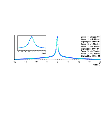
The vertex residual with respect to the true position found using the dijet photoproduction Monte Carlo sample is shown in Fig. 8. The distribution is reasonably well described by a sum of three Gaussians, interpolating between a resolution of m in the central region for event vertices found predominantly with tracks including MVD information, and long tails with a resolution of around 1cm for vertices found with tracks with little or no MVD information. The efficiency rises rapidly with the track multiplicity and approaches 100% for vertices within cm of the true vertex for events with greater than 5 tracks.
During the first commissioning stage of GTT operation with real luminosity data, between October 2002 and February 2003, the HERA beam gas related background was significantly worse than expected. To compensate, the CTD had to be operated at only 95% of the nominal high voltage setting leading to a small loss in chamber performance. In addition, since beam related background hits in the MVD were seen to bias the reconstruction, the GTT algorithm was running in a mode using only CTD information.
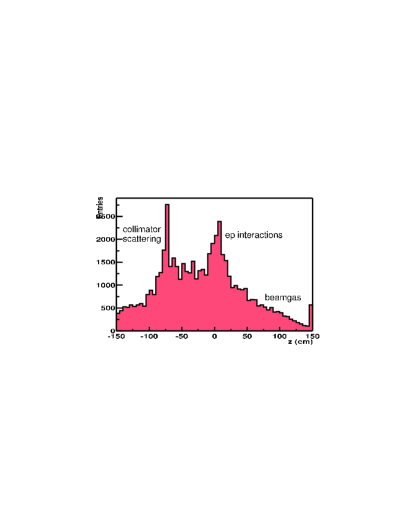
The performance and stability of the algorithm and GTT system as a whole, was well within the expectation during this period. The GTT event vertex available online is illustrated in Fig. 9 and clearly shows events from interactions in a vertex peak within cm, on the large proton-beam gas background, together with secondary scattering events from the collimator at -80cm. The efficiency found using GSLT passthrough events for reconstructing a vertex within cm of the offline vertex is found to be 84%.
XIV Summary and Outlook
The MVD DAQ and GTT system have been successfully integrated into the ZEUS experiment and their performance (latency, stability and efficiency) are satisfactory. 3.1 million events have been recorded between Nov/2002 and Feb/2003.
The GTT barrel algorithm performed well during the first commissioning luminosity running period of the upgraded HERA machine, with high stability and latencies well within those required by the ZEUS DAQ and trigger systems.
The HERA machine is currently undergoing modifications to the interaction region to reduce the beam related background. The GTT is being improved with the inclusion of a forward algorithm and the MVD data will be enabled in the barrel algorithm to improve tracking and vertex resolution and efficiency. These modifications should be available when HERA restarts in September 2003.
Acknowledgment
The author would like to thank Intel Corp. for the generous support in providing the GTT PC-farm and the network hardware.
The ZEUS MVD and GTT groups are thanked for their contributions to the DAQ and GTT systems.
References
- (1) E. N. Koffeman, Nucl. Instrum. Methods A 473, 26 (2001).
- (2) M. Feuerstack, Nucl. Instrum. Methods A 447, 89 (2000).
- (3) T. Fusayasu, K. Tokushuku, Nucl. Instrum. Methods A 436, 281 (1999).
- (4) A. Polini, ZEUS Note 99-071 (1999), unpublished.
- (5) ZEUS Collaboration, Status Report, ZEUS 1993, 1997.
- (6) A. Quadt et al., Nucl. Instrum. Methods A 438, 472 (1999).
- (7) ZEUS Collaboration, ZEUS Note 98-046 (1998), unpuplished.
- (8) A. Polini, M. Sutton, S. Topp-Jorgensen ZEUS Note 99-034 (1999), unpublished.
- (9) H. Boterenbrood et al., Nucl. Instrum. Methods A 332, 263 (1993).
- (10) M. Sutton, C. Youngman ZEUS Note 99-074 (1999), unpublished.
- (11) A. Polini, M. Pwalam, C. Youngman ZEUS Note 03-009 (2003), unpublished.
- (12) G. Hartner, ZEUS Note 98-059 (1998), unpublished.
- (13) R. Hall-Wilton, M. Sutton, B. West ZEUS Note 99-074 (1999), unpublished.