[
An Optical Lattice of Ring Traps
Abstract
A new geometry of optical lattice is proposed, namely a lattice made of a 1D stack of ring traps. It is obtained though the interference pattern of two counterpropagating beams: one of the beam is a standard gaussian beam, while the other one is a hollow beam obtained through a setup with two conical lenses. The resulting lattice is shown to have a high filling rate and a good confinement, so that it could be loaded directly from a MOT with applications in the domain of quantum computing, or with a Bose-Einstein condensate, which would have in this case a 1D ring geometry.
pacs:
32.80.Pj, 03.75.Lm, 03.67.Lx]
Optical lattices are obtained by dropping atoms in the interference pattern of coherent laser beams. Atoms undergo a force whose potential is proportionnal to the light intensity, so that cold atoms are located in confined sites, corresponding to the maximal (zero) intensity for bright (dark) lattices. By varying the shape of the interference pattern, atoms can be manipulated with an extreme precision and a relative ease: because of these possibilities, optical lattices have recently attracted increasing interest in various domains. Indeed, lattices may be loaded with atoms cooled in a magneto-optical trap (MOT), or with a Bose-Einstein condensate (BEC). Several spectacular results have been obtained recently with the latter configuration, as e.g. the realization of a BEC coherent accelerator and multiphoton beam-splitter[1], and the experimental demonstration of the quantum phase transition from a superfluid to a Mott insulator[2]. It is also possible to study more fundamental properties of the BEC, as e.g. their free expansion in a low-dimensionnal lattice[3], or their collective excitations[4]. Another attractive research field concerns low-dimensional BEC. In particular, recent experiments have demonstrated the formation of bright solitons in a 1D BEC with attractive interactions[5]. These experiments have been realized with simple waveguides, and thus a linear geometry of the BEC. Optical lattices could enable the use of more complex geometries, leading in particular to ring traps, in which BECs should exhibit new properties[6].
Optical lattices are also a key system in the realization of quantum computers with neutral atoms[7]. The qubits are the two-level atoms trapped in the lattice sites, and the interaction occurs through a cold collision between two atoms in neighboring sites. This requires to produce a lattice with at least one atom by site, a good confinement of the atoms in each site and a decoherence as low as possible. When the lattice is loaded from a MOT, the first condition is not fulfilled, simply because of the relative weak atomic density in the MOT (typically 1011 atoms/cm3), as compared to the relative high density of sites in the lattice (typically 1013 sites/cm3 in a 3D square lattice). A possibility is to limit the number of sites by using a 1D lattice, but in this case, the other conditions are not fulfilled. Indeed, if a bright lattice is used, the interactions of the trapped atoms with the light field is maximal, and the coupling between atoms and light modifies, through different physical processes, the light field, and disturb the trapping and cooling mechanisms[8]. Moreover, when such a lattice is near resonance, it induces decoherence, whereas at large detuning, the confinement of atoms, linked to the wavelength of light, decreases. In the same way, when a dark lattice is used, the atoms are not trapped, except in the particular situation of a lattice of toroidal trap. But in the proposed configurations, the radial confinement is low, of the order of the beam waist[9]. Until today, the only lattices able to strongly confine atoms with fluorescence rates of the order of 1 s, were the 3D dark lattices[10]. Therefore, a solution for a high filling rate is to increase the density of the atoms dropped in a 3D dark lattice, by using a BEC[2]. However, note that in this case, the BEC is not use for its particular coherent properties, but only because it makes possible the access to higher atomic densities.
We propose here a new lattice geometry, where each site is a ring trap, while the site density is typically 108 sites/cm Thanks to its properties, in particular the high confinement of the sites, and to its great adaptability, many applications of such a lattice can be considered. In particular, it can be loaded with a BEC, and thus could produce a 1D ring BEC, but thanks to the low density of sites, it can also be loaded directly with a MOT. The paper is organized as follows: we first discuss the principle of the lattice of ring traps, then describe the experimental realization, and finally show basic results concerning atoms loaded in the lattice.
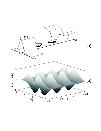
Each individual trap is a 3D dark ring, and the lattice is a 1D stack of such rings. Thus, the global shape of the potential is a bright full cylinder with a pile of ring wells inside. Such potentials can easily be obtained by making the interference of a standard gaussian beam with a counterpropagating hollow beam, as illustrated schematically in fig. 1a. Both beams have the same blue detuned frequency, so that the trapping sites correspond to the zero intensity sites. They propagate along the vertical axis with the same polarization, and the hollow beam has an inverse gaussian distribution along the radial direction , with a zero intensity in its center. The interference pattern is shown on fig. 1b through the longitudinal evolution of the transverse distribution. When the two beams are out of phase (on the figure, in with integer and the wavelength), two zeros of intensity appear symmetrically on each side of the center. Because of the cylindrical symmetry, these zeros correspond to a unique ring along the azimutal direction. On the contrary, when the two beams have the same phase (in ), the intensity profile reaches its maximum. This interference pattern results in a potential which is, in the limit of weak saturation and large detuning, proportional to the light intensity :
| (1) |
where is the detuning, the saturation intensity and the width of the atomic transition. This potential is a stack of rings separated by . Each ring has a radius of the order of the waist of the gaussian beam, and a thickness also of the order of . If is chosen as the vertical axis, the cylindrical symmetry of the potential is not broken by gravity.
In the context described above, two main properties of the lattice must be optimized: (i) the filling rate, and (ii) the confinement in the and directions. As the number of sites is fixed, the former is only linked to the number of atoms loaded in the lattice.. This number is of the order of the lattice volume, i.e. , where is the fixed length of the lattice, corresponding to the diameter of the atomic cloud used to load it. Thus in order to increase the filling rate, must be chosen as large as possible. On the other hand, the confinement following the direction is linked to the radial thickness of the rings, which accordingly must be chosen as small as possible. Therefore, the simple example given in Fig. 1, appears not to be optimal for our lattice, as both and are proportional to , while they should on the contrary be independent, in order to be adjusted separately. Moreover, an inverse gaussian beam has the disadvantage to concentrate most of the energy in the sides of the beam, where it is not useful. To summarize, a good configuration should concentrate most of the light intensity in the vicinity of , and make and independent.
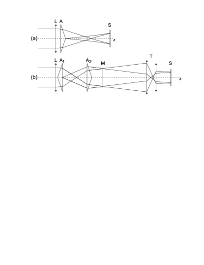
To obtain these properties, we use a hollow beam produced by a conical lens, as described in [11]. The conical lens is an axicon, i.e. an optical system that produces a line focus rather than a point focus from incident collimated beam[12]. Axicons are extensively used to produce Bessel-Gauss beams[13] or annular beams[14, 15]. The standard construction to generate an annular hollow beam is a doublet made by a converging lens and a conical lens, as illustrated in fig. 2a: the incident gaussian beam is transformed in a ring, as each part of the beam is deviated towards the optical axis . In fact, because of the diffraction on the lens vertex, the resulting beam exhibits, inside the main ring, secondary rings of lower intensity [11]. However, these rings can be easily removed with a mask, leading to a resulting annular beam with typically 80% of the intensity of the initial gaussian beam distributed in the unique ring (Fig. 3a). A second conical lens is used to collimate the radius of the ring, so that after this second lens, becomes constant with (Fig. 2b). Note that the beam is not really collimated, as its waist, which is now the thickness of the ring, evolves following the usual rules of propagation. In particular, the lens L in Fig. 2b produces a beam with a minimum thickness in M, where the mask used to suppress the secondary rings is located. The resulting hollow beam has a radius essentially dependent on the distance between the two conical lenses, while its thickness depends on the focal length of L. Thus and are adjustable independently.
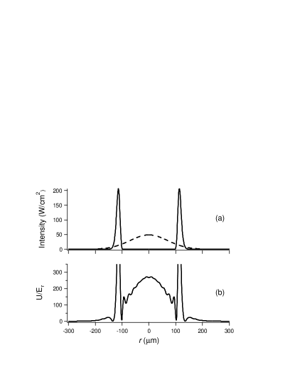
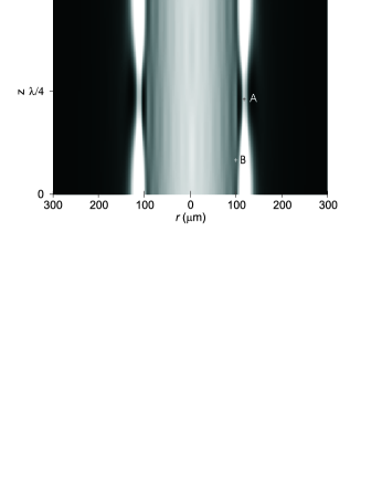
The potential is obtained by focusing the gaussian beam and the counterpropagating hollow beam at the same point, so that the wave surfaces are planes perpendicular to the propagation axis. The resulting potential has a periodicity of , with a shape depending locally on the phase between the two beams. It is illustrated through the theoretical plots of Figs. 3b and 4 where, for sake of simplicity, we used the parameters of experimental demonstration: the hollow and gaussian intensities are respectively mW and mW (fig. 3a), both beams are polarized , with GHz. Fig. 3b shows the potential transverse profile at the bottom of the wells. The geometry of the ring appears clearly, with a confinement of the order of for , and a height for the external barrier of . Secondary minima originating in the residual diffraction produced by the mask, appear inside the main ring, but because of their weak depth, they should not be annoying in most applications. A better understanding of the potential distribution can be obtained from Fig. 4, where is plotted in gray scale versus and . The potential is constituted by an external barrier, the height of which varies with . The minimum height , in point A of Fig. 4, occurs at the same as the zero (Fig. 3b). The internal barrier has a channel structure, with the lowest pass in point B (Fig. 4), at a height of , between two successive longitudinal sites. Atoms with low enough energy are confined in a torus with a half-ellipse cross-section with axes of the order of 0.1 m and 10 m. The diameter of the torus may be chosen of several hundreds of m, leading to a large capture volume. For example, with m (Fig. 4) and an initial cloud of diameter 1 mm, 6 % of the initial atoms are inside the external cylinder. Thus if the lattice is loaded with a cloud of atoms in 1 mm3, which are the typical characteristics obtained from a MOT, atoms are loaded in 2000 sites, leading to a filling rate much larger than 1. Thus the potential appears to hold the required properties, i.e. a 2D confinement and a high filling rate.
To test the feasibility of this lattice, we have implemented an experiment with the characteristics described above. Atoms of Cesium are initially cooled in a standard MOT with a detuning of from resonance. At time ms, the magnetic field is turned off, while at time ms, the detuning is increased to and the trap beam intensity is decreased: this sequence allows us to obtain at time a molasse with a temperature of 15 K, corresponding to an energy of , and 107 atoms in typically 1 mm3.
The hollow and gaussian beams are produced by two diode lasers injected by a single master diode laser in an extended cavity, which ensure the same frequency for both beams. For this demonstration, the beams are tuned GHz above the atomic transition, and are polarized, in order to increase the depth of the potential wells. In these conditions, the power of the gaussian and hollow beam, which are respectively 15 and 30 mW, are sufficient to reach the needed potential depth of . The gaussian beam has a minimum waist, at the level of the MOT, of 140 m. The axicon setup is mounted on an optical rail, to guarantee a good stability of the beam. The two conical lenses, with a vertex angle of 2∘, are separated by 146 mm. With an incident collimated beam waist equal to 645 m and a L focal length of 500 mm, we obtain a hollow beam with mm and m. A telescope located just before the trap reduces these values to m and m. We obtain in the MOT a transverse distribution of the hollow beam which is in excellent agreement with the theoretical one.
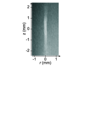
To load the cold atoms inside the lattice, the later is turned on at a time , so that when the molasse is switched off, the atoms are already distributed inside the wells. At time , the atoms start to fall under the effect of gravity, except for those which are trapped in the lattice. The free atoms needs typically ms to quit the lattice zone, so that for ms, only trapped atoms remain. To observe the atoms, we switch on during some ms the trap laser beams near resonance, and we used a low-noise cooled CCD camera to detect the fluorescence emitted by the atoms. A typical picture is shown in fig. 5: as the resolution of the imaging setup is larger than , individual rings cannot be distinguished, and so atoms appear to be distributed on a cylinder, with a diameter widening at its ends, due to the defocusing of the beams. The typical number of atoms obtained at ms is , leading to a filling rate of several atoms by sites.
In conclusion, we propose here a new lattice geometry, namely a 1D stack of ring traps, enabling large filling rates and high confinement of atoms. A preliminary experiment allows us to realize such a lattice, loading it directly from a MOT, with a typical filling rate of 10 atoms per site. Several improvements are necessary before to make such a lattice useful to e.g. the realization of a quantum gate. In particular, the detuning should be increased, together with the intensities of lattice beams. The method to load the cold atoms from a MOT in the lattice should be optimized. To avoid too much losses in the number of atoms, we plan to make this operation in two steps: first, the hollow beam is switched on just after the trap beams are switched off, so that the atoms inside the beam are trapped and remain in the cylinder. Then, the gaussian beam is switched on progressively, so that the atoms are adiabatically pushed in the ring traps. This precaution prevents the atoms to be heated by a sudden increasing of the potential. An interesting alternative would be to load the lattice with a Bose-Einstein condensate, leading to 1D BEC with a ring geometry.
The Laboratoire de Physique des Lasers, Atomes et Molécules is “Unité Mixte de Recherche de l’Université de Lille 1 et du CNRS” (UMR 8523). The Centre d’Etudes et de Recherches Lasers et Applications (CERLA) is supported by the Ministère chargé de la Recherche, the Région Nord-Pas de Calais and the Fonds Européen de Développement Economique des Régions.
REFERENCES
- [1] J. Hecker Denschlag, J. E. Simsarian, H. Häffner, C. Mckenzie, A. Browaeys, D. Cho, K. Helmerson, S. L. Rolston and W. D. Phillips, J. Phys. B: At. Mol. Opt. Phys. 35, 3095 (2002)
- [2] M. Greiner, O. Mandel, T. Esslinger, T. W. Hänsch and I. Bloch, Nature 415, 39 (2002)
- [3] O. Morsch, M. Cristiani, J. H. Müller, D. Ciampini and E. Arimondo, Phys. Rev. A 66, 021601(R) (2002)
- [4] C. Fort, F. S. Cataliotti, L. Fallani, F. Ferlaino, P. Maddaloni and M. Inguscio, Phys. Rev. Lett. 90, 140405 (2003)
- [5] K. E. Strecker, G. B. Partridge, A. G. Truscott and R. G. Hulet, Nature 417, 150 (2002); L. Khaykovich, F. Schreck, G. Ferrari, T. Bourdel, J. Cubizolles, L. D. Carr, Y. Castin and C. Salomon, Science 296, 1290 (2002)
- [6] G. M. Kavoulakis, Phys. Rec. A 67, 011601(R) (2003); R. Kanamoto, H. Saito and M. Ueda, Phys. Rev. A 67, 013608 (2003)
- [7] P. S. Jessen, D. L. Haycock, G. Klose, G. A. Smith, I. H. Deutsch and G. K. Brennen, QIC 1, 20 (2001)
- [8] J. Dalibard, Opt. Commun 68, 203 (1988); T. Walker et al, Phys. Rev. Lett. 64, 408 (1990); A. Hemmerich et al, Europhys. Lett. 21, 445 (1993)
- [9] T. Freegarde and K. Dholakia, Opt. Commun. 201, 99 (2002)
- [10] T. Esslinger, F. Sander, A. Hemmerich, T. W. Hänsch, H. Ritsch and M. Weidemüller, Opt. Lett. 21, 991 (1996)
- [11] B. Dépret, Ph. Verkerk, D. Hennequin, Opt. Commun. 211, 31 (2002)
- [12] J. H. McLeod, J. Opt. Soc. Am. 44, 592 (1954)
- [13] R. M. Herman et al, J. Opt. Soc. Am. A 8,932 (1991); J. Arlt et al, Opt. commun. 177, 297 (2000)
- [14] P.-A. Bélanger, Appl. Opt. 17, 1080 (1978)
- [15] I. Manek et al, Opt. Commun. 147, 67 (1998); L. Cacciapuoti et al, Eur. Phys. J. D 14, 373 (2001)