Variable Free Spectral Range Spherical Mirror Fabry-Perot Interferometer
Katherine Kernera, Simon M. Rochestera, Valeriy V. Yashchuka, and D. Budkera,b,∗
aDepartment of Physics, University of California at Berkeley, Berkeley, CA 94720-7300
bNuclear Science Division, Lawrence Berkeley National Laboratory, Berkeley CA 94720
∗budker@socrates.berkeley.edu
ABSTRACT
A spherical Fabry-Perot interferometer with adjustable mirror spacing is used to produce interference fringes with frequency separation , . The conditions for observation of these fringes are derived from the consideration of the eigenmodes of the cavity with high transverse indices.
PACS numbers: 42.62.Fi, 07.60.Ly, 01.50.Pa.
Introduction
A spherical mirror Fabry-Perot interferometer in the confocal configuration has many advantages over plano-plano interferometers, such as easier construction and alignment. These interferometers are used in a variety of spectroscopic applications, including laser spectrum analysis and generating frequency markers for laser frequency scans. Here we describe how one can employ a spherical mirror interferometer to produce fringes with significantly smaller free spectral range (=frequency interval between adjacent transmission peaks) by adjusting the mirror separation to specific values different from the confocal condition1. This is useful when closely- or variably-spaced frequency markers are required.
Theory
Consider a symmetric optical resonator consisting of two spherical mirrors with radius of curvature , separated by a distance in the direction2. The optical modes in this resonator are well approximated by the Hermite-Gaussian modes (in the paraxial approximation), with and direction transverse mode numbers corresponding to the number of null points in the transverse intensity profile (Fig. 1). In free space, a Gaussian beam with transverse mode numbers experiences an additional phase shift in passing through a focal region of (the Gouy phase shift) relative to a plane wave. In a resonator, the beam is confined to a finite region around the focal point, so that the total Gouy phase shift is reduced. In this case, the phase shift experienced by the beam with wavelength in a double pass (of distance ) of the resonator is
| (1) |
where the first term represents the phase shift that would be experienced by a plane wave, and the second term is the total Gouy phase shift inside the resonator. The resonance condition is that the round trip phase shift , where is an integer (the axial mode number). Substituting this condition into Eq. 1, gives the resonance frequencies:
| (2) |
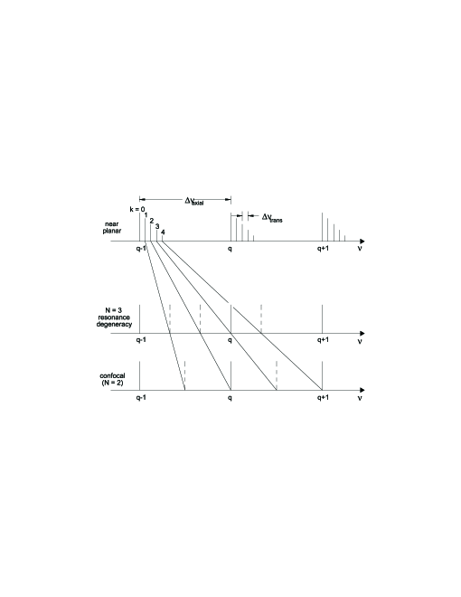
Without mode-matching (i.e. preferential coupling into a single mode), one typically excites many transverse modes of the interferometer. For example, for the interferometer used in the present work ( cm, cm, nm), the size of the fundamental transverse mode on a mirror is mm. Since the width of higher transverse modes with index is roughly , if we illuminate the input mirror with a laser beam, for example, of a width mm, we expect that transverse modes with will be excited (and even higher modes if the beam is offset from the axis). Similarly, we have for the other transverse direction. As Eq. 2 indicates, the frequencies of the transverse modes generally do not coincide with those of the axial modes, producing a complex and irregular pattern of fringes at the output as a function of the input laser frequency. As the mirror separation is changed, the frequencies of the transverse modes move with respect to those of the axial modes (Fig. 2). In the confocal configuration (where ), every other transverse mode becomes degenerate with an axial mode, producing a pattern of fringes with half the axial spacing (). This removes the need for mode matching and is one of the reasons a confocal interferometer is particularly useful3.
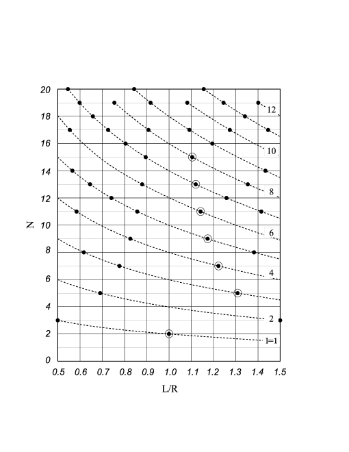
If the mirror separation is adjusted away from the confocal condition, we can find higher-order degeneracies where every transverse mode is degenerate with an axial mode, i.e. , where are integers. The output fringes in this case have smaller . From Eq. 2, one obtains the resonance conditions
| (3) |
The additional conditions are added to avoid double counting resonances with higher degeneracies.
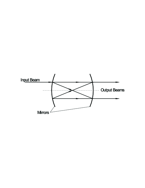
The appearance of resonances corresponding to different values of may also be understood in the ray-tracing approach applied in Ref. 4. In that work, the relation of the extra cavity resonances to the appearance of closed ray paths and applications to laser resonators and absorption cells are discussed. For an arbitrary mirror separation, a light ray (coming into the cavity off-axis) never overlaps with its original location on the mirror. However, in the confocal configuration, the beam returns to its original position after traversing the cavity four times (Fig. 3). Two spots may usually be observed where the beam hits the output mirror and is partially transmitted. At certain mirror spacings (given by Eq. 3), different from the confocal separation, the beam returns to its original position after making more than four traversals. In this situation, spots are observed, where corresponds to the resonance number described above.
Apparatus
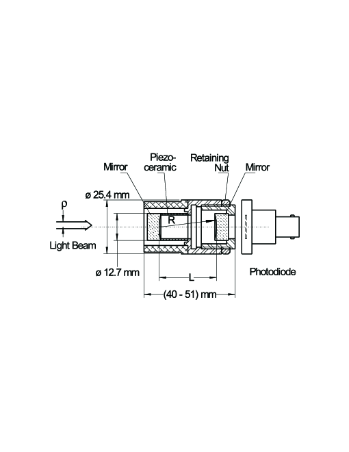
In recent years, inexpensive home-made confocal devices have found broad application both in research and instruction laboratories. In our design5 (Fig. 4), the body of the interferometer is constructed of two fine-threaded metal pipes. One pipe threads into the other allowing accurate adjustment of the mirror separation. A standard concave mirror (intensity reflectivity , radius of curvature cm) is glued directly to one of the pipes. The second identical mirror is glued to a piezo-ceramic hollow cylinder, which, in turn, is glued to the second metal pipe. Application of voltage between the walls of the piezo-ceramic tube displaces the mirror, providing frequency tuning of the interferometer, typically, by several free spectral ranges per 100 V. While scanning the interferometer and observing the transmission fringes, one adjusts the average mirror separation to achieve the confocal (or higher-order degeneracy) condition (tolerance mm), where the width of the observed transmission peaks is minimal and their amplitude is at a maximum. Once the desired separation between the mirrors is found, the spacing may be fixed by tightening the retaining nut.
Experimental Results
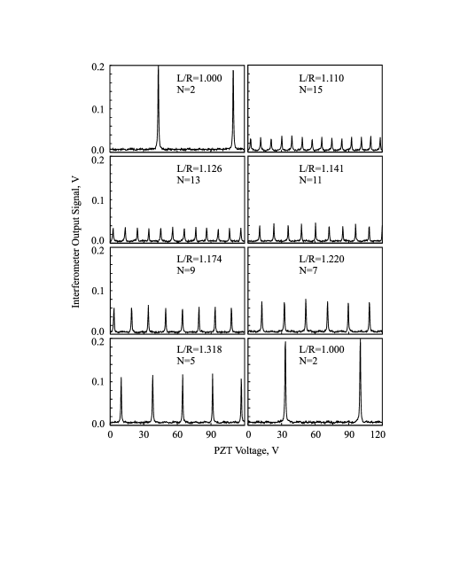
We have investigated the properties of the device described above at mirror separations different from the confocal separation. Narrow-band light from a commercial diode laser at nm was directed into the interferometer. The mirror separation was scanned by applying voltage to the piezo-ceramic cylinder, and the output fringes were observed. The average mirror separation was adjusted to values corresponding to resonances given by Eq. 3. We were able to produce well-resolved fringes with up to 15 (Fig. 5), and measured the mirror spacings corresponding to the resonances. Since a smaller number of modes are degenerate between each other for compared to the confocal case, the peak transmission of the interferometer is reduced, roughly as . The widths of the transmission peaks corresponding to a given mode are mostly determined by the mirrors’ reflectivity and do not change with . Thus, the effective finesse (the ratio of to the transmission peak width at half maximum) of the device also scales as . However, the decrease in as increases results in fringes with small adjustable , which allows the use of a single compact device in place of multiple interferometers of much greater length. The measured mirror separations corresponding to the resonances coincided with the prediction of the theory of Eq. 3 within experimental uncertainty of microns. The predicted and measured values of are shown in Fig. 6.
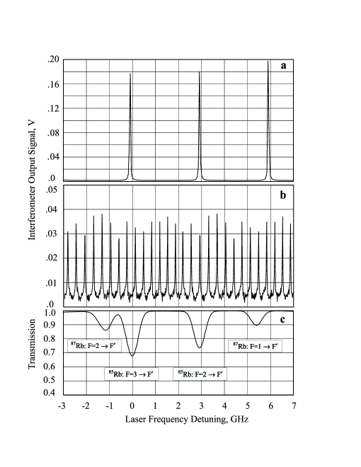
Examples of experimental transmission patterns of an interferometer with mirror separation in the vicinity of a confocal resonance and a resonance with are given in Figure 7. This Figure also shows the Doppler-limited absorption spectrum of the Rb D2 line (Fig. 7c). While the confocal fringes are adequate as frequency markers for the Doppler-broadened scan, the higher order fringes are useful for higher resolution scans, e.g. when a scan extends over just one of the four peaks shown in Fig. 7c. which is often the case in Doppler-free spectroscopy6,5.
This work has been supported by NSF, grant PHY-9733479 and by ONR, grant N00014-97-1-0214.
REFERENCES
- 1
-
D. Budker, S. Rochester, and V. V. Yashchuk, Rev. Sci. Instr. 71(8), (2000).
- 2
-
In this discussion we follow the approach given by A. E. Siegman. Lasers, University Science Books, Mill Valley, California, 1986.
- 3
-
As the transverse mode number increases, the paraxial approximation breaks down. In order to limit the order of the transverse modes excited, we require that , where is a typical size characterizing the width and offset from the axis of the input laser beam. This means that is limited to for the interferometers used in this work. Larger beam sizes and offsets lead to broader and asymmetric transmission peaks.
- 4
-
D. Herriott, H. Kogelnik, and R. Kompner, Appl. Opt. 3(4), 523(1964).
- 5
-
D. Budker, D. J. Orlando, and V. Yashchuk, Am. J. Phys. 67, 584 (1999).
- 6
-
W. Demtrder. Laser specroscopy, Springer-Verlag, Berlin, Heidelberg, New-York, 1998.