A New Implementation of the Region-of-Interest Strategy for the ATLAS Second Level Trigger
Abstract
Among the many challenges presented by the future ATLAS detector at the LHC are the high data taking rate and volume and the derivation of a rapid trigger decision with limited resources. To address this challenge within the ATLAS second level trigger system, a Region-of-Interest mechanism has been adopted which dramatically reduces the relevant fiducial volume necessary to be readout and processed to small regions guided by the hardware-based first level trigger. Software has been developed to allow fast translation between arbitrary geometric regions and identifiers of small collections of the event data. This facilitates on-demand data retrieval and collection building. The system is optimized to minimize the amount of data transferred and unnecessary building of complex objects. Details of the design and implementation are presented along with preliminary performance results.
I INTRODUCTION
ATLAS (A Toroidal LHC ApparatuS) is one of the four detectors currently being built around the LHC (Large Hadron Collider) at the European Organization for Nuclear Research (CERN) in Geneva, Switzerland. The LHC will collide protons at a centre-of-mass energy of 14TeV. ATLAS is a multipurpose detector designed to have a 4 hermeticity around the interaction region. The physics goals of ATLAS are numerous: from Higgs searches, to Top physics, from SUSY searches to QCD physics, not forgetting physics as well as exotic searches. In addition, part of the excitement for reaching this energy frontier is the discovery potential associated with this unchartered territory. These physics requirements combined with a bunch crossing rate of 40 MHz in addition to an average of 25 inelastic proton-proton underlying interactions in each bunch crossing (at a design luminosity of ) put very stringent constraints on the data acquisition and trigger system.
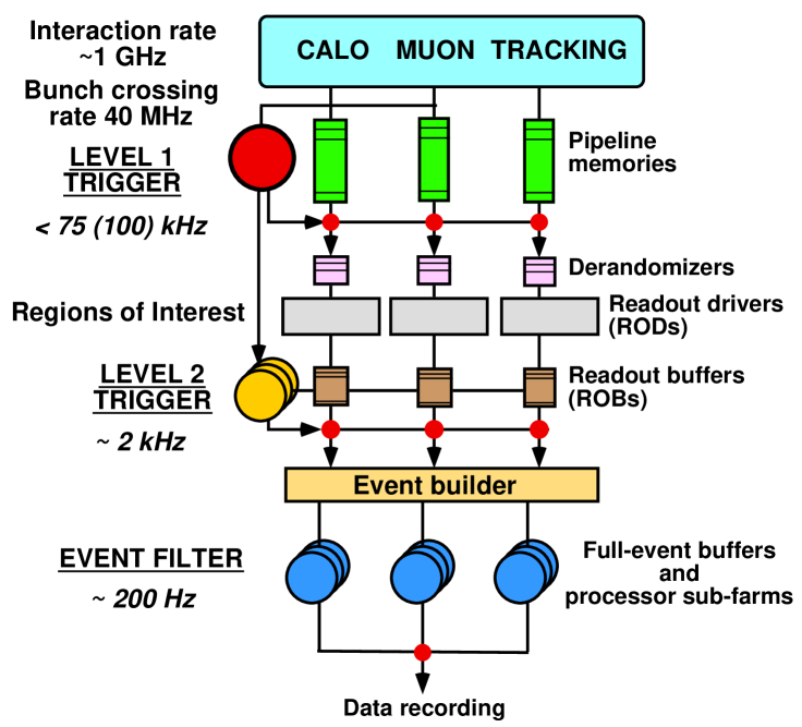
The overall architecture of the three-level ATLAS trigger system is shown in figure 1 TP . It is designed to reduce the nominal 40 MHz bunch crossing rate to a rate of about 200 Hz at which events, that will have a size of about 1.6 MB on average, will be written to mass storage. The first stage of the trigger, LVL1, is hardware-based and it reduces the rate to about 75KHz. Using the fast calorimeter and muon sub-detectors, it has a latency (time taken to form and distribute the LVL1 trigger decision) of about 2.5 . During that time, the data from all the sub-detectors (about electronic channels) are kept in pipeline memories. After the LVL1 decision, selected data fragments are transferred to the Readout Drivers (RODs) and then to the Readout Buffers (ROBs). It is foreseen that there will be a total of about 1700 ROBs. The second stage of the trigger system, LVL2, is software-based and it reduces the rate to about 2KHz. Making use of the so called Region-of-Interest mechanism the average latency is about 10ms. In order to achieve this goal, the main characteristic of this stage is a fast rejection achieved by optimized trigger algorithms. The last stage of the trigger system, the Event Filter, occurs after the event building process. At this stage, the average latency is about 1s. The goal of the Event Filter is both to reduce the rate to about 200Hz, necessary for mass storage, but also to classify the events. Hence full calibration and alignment information is available at this stage. The trigger algorithms used for this stage have much in common with the offline algorithms and massive reuse of those is foreseen. The LVL2 and the Event Filter stages are commonly referred to as the High Level Trigger (HLT).
I.1 The Region-of-Interest Mechanism
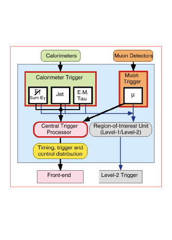
An important piece of the strategy of the ATLAS trigger relies on the Region-of-Interest (RoI) mechanism for which the LVL2 trigger makes use of information provided by the LVL1 trigger in localized region of the calorimeter and muon sub-detectors. This process is shown schematically in figure 2. The information contained in the RoI typically include the position ( and ) and the of the candidate objects as well as energy sums. Candidate objects selected by the LVL1 can be high- muons, electrons or photons, hadrons or taus, and jets. The energy sums include the missing- vector and the scalar value. For all selected LVL1 events, the RoI information is sent to the LVL2 using a dedicated data path. Making use of this RoI information, the LVL2 algorithms only transfer the necessary ROBs in order to arrive quickly at a LVL2 decision. It is important to note that all the data from all the sub-detectors with full granularity is available for the LVL2 algorithms if necessary. However, typically only a small fraction of the detector, centred around the RoI information selected by the LVL1, is needed by the LVL2 algorithms. On average there are a few RoI per event and as a consequence to this mechanism only a few percent of the total event data is required at the LVL2 stage. On the other hand, even though the bandwidth requirements on the Data Acquisition system is much reduced, it makes for a more complex system.
I.2 The Data Access
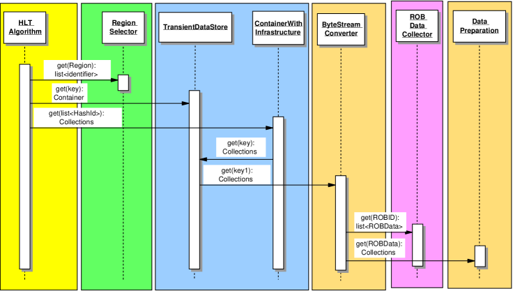
As discussed above, the Region-of-Interest mechanism allow for an optimized retrieve of the data necessary to perform the LVL2 decision. Figure 3 shows in more details the sequence associated with the data access. The data is stored in collections within the Transient Data Store (TDS) paolo . These collections are organized inside a ContainerWithInfrastructure for easy retrieval and sorting. The collections are identified uniquely via an offline identifier offlineid . We can see from the diagram that the HLT algorithm first ask the RegionSelector tool for the list of collection identifiers associated with a particular region, that could correspond for example to an region that would come from LVL1. With the list of collection identifiers in hand, the HLT algorithm request the associated data to the TDS. If the data is already cached within the TDS, the requested collections are returned. If the data is not cached, the TDS launches the ByteStreamConverter which goal is to fill the collections in the TDS using the data in ByteStream format. To get a hold of this data, the ByteStreamConverter must request specific ROBs to the ROBDataCollector. Finally, at LVL2 there is the possibility to do some data preparation from within the ByteStreamConverter, which leads to a faster execution of the LVL2 trigger algorithms. One consequence from this sequence is the fact that the RegionSelector tool plays a central role within the trigger chain, since every Trigger Algorithm that needs access to the data in a certain region will have access to this tool. Another remark that stems from this data access sequence is the need for an optimization of the collection granularity. There needs to be a trade off between a useful navigation for the trigger algorithms and a minimization of the data requests. Finally, we mentioned that the collection request was made using the offline identifiers, rather than the online identifiers. This choice comes primarily from two issues, one is the fact that the current design for the trigger architecture calls for the use of offline code in the online environment. That is to say, both the trigger algorithms and the architecture in which they run can be developed in an offline environment and be directly ported to the online environment. The benefits are numerous: this will facilitate the development of algorithms; this will allow the study of the boundary between LVL2 and Event Filter and it will lead to easy performance studies for physics analysis. The second issue related with the use of offline identifiers for the collection and the RegionSelector comes from the fact that a possible region for which a trigger algorithm could require data is the InnerDetector sub-detectors, for which there are no LVL1 online identifiers.
II THE REGION SELECTOR TOOL
Having described the usefulness and environment surrounding the RegionSelector tool we now turn to its requirements and implementation.
II.1 Requirements
As we have just seen, the RegionSelector tool is central to any LVL2 trigger algorithm, hence its foremost requirement is that it should be fast and use up only a fraction of the available latency at LVL2. Another requirement imposed on the RegionSelector is the fact that it should translate an arbitrary geometrical region into a list of collection identifiers. Such a region can be a simple cone that span the various sub-detectors. It can also be a more complex cone which accounts for the uncertainty in the position of the primary vertex, coming from the beam spread. In that case, has a radial dependence. Finally, another geometrical region of interest is that of a helical road, which could correspond for example to a reconstructed track in need of confirmation by a more refined Event Filter algorithm which has access to calibration and alignment constants. In the current implementation of the RegionSelector tool the innermost sub-detectors take into account the direction spread while the outermost sub-detectors follow a cone.
II.2 Implementation
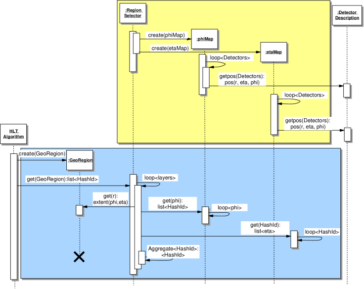
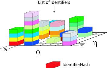
In figure 4 we show the sequence diagram associated with the RegionSelector tool. We can distinguish two main parts, the top one represents the initialization phase, and the lower part shows the execution phase. At initialization two maps are filled for each layer of each sub-detector: a map between the index and a set of identifiers, and a second map between an identifier and a vector of a range in . Figure 5 shows schematically the concept of a set of identifiers corresponding to a value in and a range in . During the execution phase, the algorithm asks for the list of identifiers corresponding to a range in and a range in , for a specified sub-detector. There is an outer loop over the layers, then there is a loop over the range to get the associated sets of identifiers. Following this step there is also a loop over the identifiers to check if the value is within the required range. The built identifier list is then returned to the algorithm. This procedure ensures that there are no duplicate identifier within the list. Care must be taken regarding the compact boundary.
A key ingredient to the RegionSelector tool are mappings made by the sub-detector communities that tie together a range in and and a collection identifier. Those mappings are then used to make the internal maps during the initialization period of the RegionSelector. As mentioned in section I.2, there needs to be an optimization performed for each sub-detector concerning the granularity of the collections. In the current implementation table 1 shows the current collection granularity for each sub-detector, as well as the total number of ROBs for this sub-detector. For the Pixel sub-detector a collection corresponds to a module, which is a single silicon wafer. For the silicon strip detector (SCT) the collection granularity corresponds to a side of a module which is a bonded pair of wafers whose strips are oriented in the same direction, either axial or stereo. For the Transition Radiation Tracker (TRT) sub-detector, the collection granularity corresponds to a radial straw layer in the barrel and to 1/32 in in the endcap wheels. For the Liquid Argon calorimeter the collection granularity is that of a Trigger Tower while for the barrel hadronic Tile calorimeter the collection granularity is a phi wedge. Finally for the muon spectrometer there are four technologies used. Two types of chambers are used for trigger purposes: the Resistive Plate Chambers (RPC) and the Thin Gap Chambers (TGC); and two types of chambers are used for precision measurements: the Monitored Drift Tube chambers (MDT) and the Cathode Strip Chambers (CSC). For all of the muon spectrometer the collection granularity corresponds to a single chamber. For more information on each sub-detector see for example atlas .
| Collection | Number | Num. ROBs | |
|---|---|---|---|
| Pixel | module | 1744 | 81 |
| SCT | side of module | 8176 | 256 |
| TRT | straw layer | 19008 | 256 |
| LAr | Trigger Tower | 7168 | 768 |
| Tile | module | 256 | 32 |
| muon MDT | chamber | 1168 | 192 |
| muon CSC | chamber | 32 | 32 |
| muon RPC | chamber | 574 | 32 |
| muon TGC | chamber | 1584 | 32 |
III TIMING MEASUREMENTS
As mentioned earlier, the main requirement for the RegionSelector tool is that it should only use up a small fraction of the available latency at LVL2. Preliminary timing measurements were performed on a 1GHz Pentium III machine using the TAU (Tuning and Analysis Utilities) TAU timing tool. Table 2 shows the timing measurements for various sub-detectors for different ranges in and .
| 0.1 | 0.2 | 0.5 | ||
|---|---|---|---|---|
| Pixel ( = 0.06) | 0.20 | 0.22 | 0.23 | |
| SCT ( = 0.11) | 0.56 | 0.59 | 0.62 | |
| TRT ( = 0.23) | 1.05 | 1.12 | 1.21 | |
| 0.1 | LAr ( = 0.06) | 0.33 | 0.33 | 0.35 |
| Tile ( = 0.008) | 0.03 | 0.03 | 0.03 | |
| MDT ( = 0.038) | 0.06 | 0.06 | 0.06 | |
| RPC ( = 0.009) | 0.05 | 0.05 | 0.06 | |
| Pixel | 0.22 | 0.22 | 0.23 | |
| SCT | 0.60 | 0.61 | 0.63 | |
| TRT | 1.13 | 1.15 | 1.23 | |
| 0.5 | LAr | 0.33 | 0.34 | 0.35 |
| Tile | 0.03 | 0.03 | 0.03 | |
| MDT | 0.06 | 0.06 | 0.07 | |
| RPC | 0.05 | 0.05 | 0.06 | |
We can see from the results that the timing is mainly independent on the extent of the and range. If one looks at the LAr calorimer timing and arbitrarily divide by 3 to account for a 4GHz machine, one gets a timing of the Region Selector of about 0.11ms. Since preliminary timing measurements of LVL2 calorimeter algorithms are of the order of 1ms on a 1GHz machine, we get a combined RegionSelector and algorithm timing of less than 0.5ms, extrapolated to a 4GHz machine. This number is well below the expected 10ms average latency allowed at LVL2. Note that the timing for the data access is not included in this number.
IV CONCLUSION
We have shown an implementation of a tool used to translate a region into a list of collection identifiers. This tool is used by all algorithms that request data access in a given region of the ATLAS detector. Although this tool is of crucial importance at LVL2, specially when combined with the Region-of-Interest mechanism, it can also be of used in the Event Filter and in offline reconstruction whenever an algorithm is interested in a particular seed, be it a simple sub-detector region or an object spanning a sub-detector region. Already the timing budget of this tool is within the accepted latency, scaled to a representative machine speed for 2007. It is foreseen that continuous improvements will be achieved in the implementation and that more complex geometrical regions will be supported.
Acknowledgements.
The authors wish to thank the ATLAS PESA core software group. The authors also wish to thank the various sub-detector communities for their assistance in providing the necessary mappings, central to the implementation of the RegionSelector tool: K. Assamagan, S. Goldfarb, G. Gorfine, F. Luehring, H. Ma, S. Sivoklokov, and S. Solodkov.References
-
(1)
The ATLAS High Level Trigger group
http://atlas.web.cern.ch/Atlas/GROUPS/
DAQTRIG/HLT/AUTHORLISTS/chep2003.pdf 222S. Armstrong, J.T. Baines, C.P. Bee, M. Biglietti, A. Bogaerts, V. Boisvert, M. Bosman, S. Brandt, B. Caron, P. Casado, G. Cataldi, D. Cavalli, M. Cervetto, G. Comune, A. Corso-Radu, A. Di Mattia, M. Diaz Gomez, A. dos Anjos, J. Drohan, N. Ellis, M. Elsing, B. Epp, F. Etienne, S. Falciano, A. Farilla S. George, V. Ghete, S. González, M. Grothe, A. Kaczmarska, K. Karr, A. Khomich, N. Konstantinidis, W. Krasny, W. Li, A. Lowe, L. Luminari, H. Ma, C. Meessen, A.G. Mello, G. Merino, P. Morettini, E. Moyse, A. Nairz, A. Negri, N. Nikitin, A. Nisati, C. Padilla, F. Parodi, V. Perez-Reale, J.L. Pinfold, P. Pinto, G. Polesello, Z. Qian, S. Rajagopalan, S. Resconi, S. Rosati, D.A. Scannicchio, C. Schiavi, T. Schoerner-Sadenius, E. Segura, T. Shears, S. Sivoklokov, M. Smizanska, R. Soluk, C. Stanescu, S. Tapprogge, F. Touchard, V. Vercesi, A. Watson, T. Wengler, P. Werner, S. Wheeler, F.J. Wickens, W. Wiedenmann, M. Wielers, H. Zobernig - (2) ATLAS HLT/DAQ/DCS Groups, ATLAS High-Level Triggers, DAQ and DCS: Technical Proposal, CERN/LHCC/2000-17, March 2000
- (3) P. Calafiura, StoreGate: a Data Model Toolkit for the Atlas Software Architecture, Proceedings CHEP03, MOJT008
- (4) S. Goldfarb and A. Schaffer (editors), Definition of Offline Readout Identifiers for the ATLAS detector, ATLAS Internal Note ATLAS-SOFT-2001-004
- (5) ATLAS collaboration, ATLAS detector and physics performance Technical Design Report, CERN/LHCC/99-14, May 1999
- (6) http://www.cs.uoregon.edu/research/paracomp/tau/