Impact of the Wiggler Coherent Synchrotron Radiation Impedance on the Beam Instability111Work supported by the Department of Energy contract DE-AC03-76SF00515
,,Submitted to Physical Review Special Topics—Accelerators and Beams)
Abstract
Coherent Synchrotron Radiation (CSR) can play an important role by not only increasing the energy spread and emittance of a beam, but also leading to a potential instability. Previous studies of the CSR induced longitudinal instability were carried out for the CSR impedance due to dipole magnets. However, many storage rings include long wigglers where a large fraction of the synchrotron radiation is emitted. This includes high-luminosity factories such as DAPHNE, PEP-II, KEK-B, and CESR-C as well as the damping rings of future linear colliders. In this paper, the instability due to the CSR impedance from a wiggler is studied assuming a large wiggler parameter . The primary consideration is a low frequency microwave-like instability, which arises near the pipe cut-off frequency. Detailed results are presented on the growth rate and threshold for the damping rings of several linear collider designs. Finally, the optimization of the relative fraction of damping due to the wiggler systems is discussed for the damping rings.
pacs:
29.27.Bd; 41.60.Ap; 41.60.Cr; 41.75.FrI Introduction
When an electron bunch passes the curved trajectory inside a dipole, the coherent synchrotron radiation (CSR) induces an impedance Mur97 ; Derb95 ; Warnock90 ; KYNg90 . The CSR impedance is known to impact single pass bunch compressors where the beam currents are extremely high BraunPRL ; BraunPRST ; H01 ; L02 but it is also possible that CSR might cause a microwave-like beam instability in storage rings. A theory of such an instability in a storage ring has been recently proposed in Ref. SH02 where the impedance is generated by the synchrotron radiation of the beam in the storage ring bending magnets.
A similar instability may arise due to coherent synchrotron radiation in long wigglers. Many storage rings have used large wiggler systems to reduce the damping times and control the beam emittance. In particular, the high luminosity colliding beam factories DAPHNE DAPHNE , PEP-II PEPII , KEK-B KEKB , CESR-C CESRC all have wiggler systems that can radiate significantly more power than is radiated in the arc bending magnets. Similarly, damping ring designs for future linear colliders rely on large wiggler systems to obtain the required damping rates where, again, more power can be radiated in the wiggler systems than in the arc bending magnets.
In a previous study, the wakefield and impedance in a wiggler with large parameter has been obtained WRS02 based on the work of Saldin et al. Saldin98 . In this paper, we study the impact of the wiggler synchrotron radiation impedance on the beam longitudinal dynamics in rings with dipoles and wigglers. We focus our attention on the limit of a large wiggler parameter because this is the most interesting case for many applications.
The paper is organized as follows. In Sec. II, we will briefly review the theory of the beam instability in a ring due to the CSR impedance SH02 . Using the synchrotron radiation impedance of a wiggler WRS02 , we study the beam instability problem for a ring including both dipoles and wigglers in Sec. III. In Sec. IV, we then focus on a low-frequency microwave-like CSR instability near the pipe cut-off frequency which is the primary limitation. Finally, in Sec. V, we discuss effect of the CSR instability on the design optimization of damping rings for future linear colliders. Finally, we give some discussions and conclusion in Sec. VI.
II Longitudinal beam instability
We consider the longitudinal dynamics of a thin coasting beam. The beam can be described with a longitudinal distribution function . The positive direction for the internal coordinate is pointing to the direction of the motion. The relative energy offset of a particle having energy with respect to the nominal energy is expressed as . The position of the reference particle in the beam line is with equal to the speed of light in vacuum.
The longitudinal beam instability due to the synchrotron radiation impedance in a ring has been studied theoretically by Stupakov and Heifets SH02 . In this section, we briefly review and reproduce the equations we need for our study in this paper. The reader is advised to refer to reference SH02 for the details of the theory.
For a matched beam, one can use a 1-D Vlasov equation to describe the evolution of the longitudinal distribution function .
| (1) | |||||
where, the slippage factor is defined as
| (2) |
with equal to the momentum compaction factor. For ultrarelativistic beams, we have . Based on our definition of , the sign convention for is then the following. If a particle with a higher energy than the nominal energy, i.e., , would go to the head of the bunch, then the beam line provides a negative . According to this convention, then in a simple bending magnet, we will have , while in a wiggler, we have .
| NLC | TESLA | ATF | |
| Circumference /km | 0.3 | 17 | 0.14 |
| Dipole radius /m | 5.5 | 80 | 5.7 |
| Total bending angle | 1 | 5/3 | 1 |
| Momentum compaction | 2.95 | 1.2 | 19 |
| Synchrotron frequency /kHz | 3.5 | 0.8 | 17.4 |
| Extracted X emittance m | 3 | 8 | 5 |
| Extracted Y emittance m | 2 | 2 | 5 |
| Energy /Gev | 1.98 | 5 | 1.3 |
| Energy rms spread | 9.09 | 9 | 6 |
| Bunch rms length /mm | 3.6 | 6 | 5 |
| Particles in a bunch | 0.75 | 2 | 1 |
| Wiggler peak field /T | 2.15 | 1.5 | 1.88 |
| Wiggler period /m | 0.27 | 0.4 | 0.4 |
| Wiggler total length /m | 46.24 | 432 | 21.2 |
| Wiggler -function /m | 1.87 | 6.67 | 6 |
| Pipe radius /cm | 1.6 | 2 | 1.2 |
| 2.2 | 13.4 | 1.8 | |
| Cut-off wavelength /mm | 4.9 | 1.8 | 3.1 |
| Threshold at cutoff (wiggler off) | 0.60 | 27.44 | 0.95 |
| Threshold at cutoff (wiggler on) | 0.52 | 24.56 | 0.76 |
| Growth time at cutoff (wigger off) | 54.9 | N/A | 34.3 |
| Growth time at cutoff (wigger on) | 32.9 | N/A | 6.5 |
The distribution function is written as a sum of the equilibrium distribution function and a perturbation, , with . We look for a perturbation as
| (3) |
where is the wavenumber, the frequency. Linearizing the 1-D Vlasov Eq. (1) leads to the dispersion relation SH02 :
| (4) |
which determines the existence of a solution as in Eq. (3). Here, m is the classical electron radius and is the Lorentz factor. In addition,
| (5) |
is the CSR impedance and the wake Green function describes the interaction of two particles due to the synchrotron radiation where for while for . The positive values of correspond to the energy loss and the negative values imply the energy gain.
We assume that the initial energy distribution function is a Gaussian, i.e., , where is the linear density, i.e., the number of particles per unit length. In this case, Eq. (4) can be rewritten as,
| (6) |
where, ; and . The upper (lower) sign in Eq. (6) refers to the case of a positive (negative) . We refer the reader to Ref. SH02 for further details.
III Storage Rings with Wigglers
As mentioned, a number of storage rings utilize long damping wigglers where a significant fraction of the energy loss per turn is emitted. As concrete examples, we study the NLC main damping ring Andy02 , the TESLA damping ring Deck9901 , and the KEK ATF prototype damping ring ATF02 . Parameters are given in Table 1.
In our paper, we use the steady state CSR impedance and assume a distributed impedance model. For a dipole, the steady state CSR impedance is Mur97 ; Derb95
| (7) |
with
| (8) |
The wiggler impedance is computed in Ref. WRS02 . Hence, the total impedance is then
| (9) |
where, , , and are the dipole bending radius, the total bending angle, the wiggler total length and the damping ring circumference given in Table 1 respectively.
To study the instability, we numerically solve the dispersion relation Eq. (6). Since we are assuming a coasting beam model, we only consider instability wavelengths short compared to the bunch length.
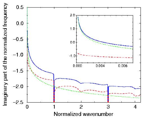
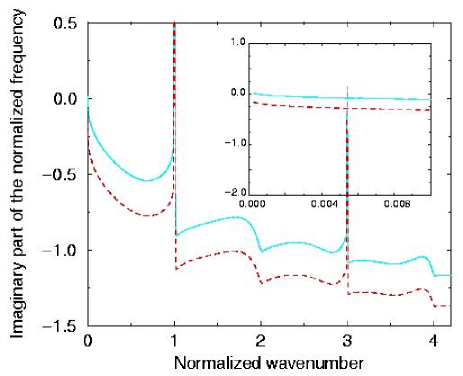
In Fig. 1, the imaginary part of is plotted as a function of the instability wavenumber for the NLC main damping ring using the parameters listed in Table 1. At low frequencies, the dipole CSR impedance dominates while at shorter wavelengths the wiggler CSR impedance is usually more important. In the region where Im(), the beam is stable and this is true for all regions except at the longest wavelengths as shown in the inset. This low frequency instability will be discussed in the following section.
Similar calculations were made for the TESLA “dog-bone” damping ring, where the total bending angle is about , and the KEK ATF prototype damping ring. For the design current in the TESLA damping ring, the impedance from the dipoles and wigglers will not drive an instability while the results for the ATF are very similar to those of the NLC damping ring shown in Fig. 1.
One interesting effect can be seen at the wiggler radiation fundamental frequency and the odd harmonics where the ring is actually stabilized by the wiggler impedance. This is opposite to the single-pass behaviour through a wiggler where there is an instability at the wiggler fundamental frequency usually refered to as the FEL instability. The effect will be discussed further in Appendix A but is a direct result of the positive sign of the momentum compaction in the ring.
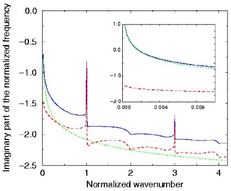
To illustrate this, Fig. 2 is a plot for the NLC damping ring with identical wiggler and arc parameters but the momentum compaction is assumed to be opposite in sign. Here, one can see that at low frequencies the growth is slightly lower. In contrast, the wiggler impedance makes the system less stable at the wiggler fundamental unlike the case with positive momentum compaction. Furthermore, if the magnitude of the momentum compaction is reduced, the system will become unstable similar to that illustrated in Appendix B. This is similar to the FEL instability however, it is also noted in Appendix A that our theory does not correctly treat the full FEL instability.
IV Low-frequency CSR instability
As seen in Figs. 1 and 2, the instability is most important at relatively low frequency. The longest instability wavelength that is possible is determined by two effects: first, the instability wavelength has to be short compared to the bunch length and, second, the vacuum chamber causes an exponential suppression of the synchrotron radiation at wavelengths greater than the ‘shielding cutoff’ Warnock90
| (10) |
Here, is the dipole bending radius, and is the vacuum chamber half height. The numerical coefficient of Eq. (10) assumes that the vacuum chamber is made up of two infinitely wide plates. Different cross sections give different numerical factors SK02 . Given the previous discussion, the threshold will be the lowest at the smaller of the bunch length or the ‘shielding cutoff’ wavelength.
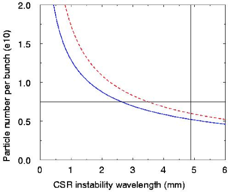
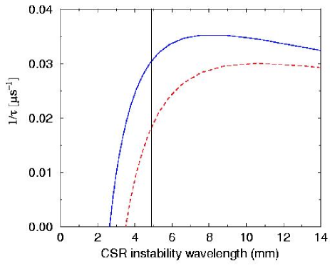
For the NLC main damping ring, we find that perturbations with wavelengths mm are not stable due to the dipole CSR impedance alone. Adding the CSR impedance from the wiggler causes perturbations with wavelengths mm to be unstable. In Fig. 3, the threshold particle number is plotted as a function of the perturbation wavelength. Next, in Fig. 4, the growth rate, which is defined as the inverse of the time needed for the perturbation to grow by a factor of
| (11) |
is plotted versus the perturbation wavelength. Based on the parameters in Table 1 and Eq. (10), the ‘shielding cutoff’ wavelength is computed to be mm. At this cutoff wavelength, the threshold currents and growth time are summarized in Table 1. The growth time is significantly faster than the synchrotron period, in agreement with the analysis for a microwave-like instability.
It is clearly seen that the threshold current decreases as we approach the longer wavelength perturbations, however, the growth rate is not monotonic. This is the result of two opposite mechanisms: one is the energy modulation growth due to the CSR impedance, and the other is the Landau damping. For very long wavelength perturbation, Landau damping effect is small, hence, we could expand the denominator of the integrand in Eq. (4) to get
| (12) |
which indicates that Im() , i.e., the growth rate will increase for a shorter wavelength perturbation, since , with . This is shown in Fig. 4: when we approach from the long wavelength perturbation to the short wavelength perturbation, the growth rate increases.
However, this process stops when Landau damping becomes effective. The finite energy spread in the beam will produce a phase mixing due to the slippage and this will destroy density modulation due to the CSR induced energy modulation. The Landau damping due to the phase mixing is more serious for short wavelength perturbations. This damping can be seen in the second term of Eq. (1), or more clearly, in the denominator of the dispersion relation in Eq. (4). This is demonstrated in Fig. 4, the growth rate finally decreases when we approach very short wavelength, and eventually, the system becomes stable.
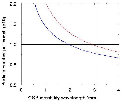
For the KEK ATF prototype damping ring, the cut-off wavelength would be about mm according to Eq. (10). In Fig. 5, the threshold particle number is plotted as a function of the perturbation wavelength. Taking the dipole CSR impedance alone, for the single bunch charge, the instability sets in for perturbations with wavelengths mm. Adding the wiggler CSR impedance, the electron beam would be unstable for perturbations with wavelengths mm. Other results are summarized in Table 1.
It is interesting to note that in both the NLC and the ATF damping rings roughly twice as much synchrotron radiation power is emitted in the wiggler as in the arc dipoles. However, the instability threshold is not dramatically impacted by the additional radiation in the wiggler and decreases by less than a factor of two in each case. This arises because of the very different low frequency behavior of the impedances.
We can use a simple scaling analysis to understand this. According to Eq. (7), the dipole CSR impedance scales as . Similarly, the low frequency behavior of the wiggler impedance is WRS02
| (13) |
which is accurate enough for practical calculation in , where is the wiggler fundamental radiation wavenumber:
| (14) |
and the wiggler parameter is approximately , with the peak magnetic field of the wiggler in units of Tesla and the period in meters. Thus, the wiggler CSR impedance scales as Re(), and Im(), which have a weaker scaling than when , i.e., the CSR impedance from the wiggler is weaker than that from the dipole when we approach low frequency region.
Hence, it suggests an optimization of the damping ring design where a larger fraction of radiation is emitted in the wigglers as will be discussed subsequently.
V Damping Ring Optimization
Damping rings are used in linear colliders to attain the very small transverse emittances that required to attain the desired small spot sizes at the collision point. In the damping rings, the emission of synchrotron radiation damps the phase space volume of the injected beams towards the equilibrium values. An -folding reduction of the transverse phase space occurs after the emission of synchrotron radiation energy comparable to the beam energy.
There are usually three conflicting requirements on the damping rings: first, the equilibrium emittances must be small which usually requires weak bends and strong focusing; second, the dynamic aperture must be large to accept the injected beams and this is difficult to attain in a strong focusing storage ring; and, third, the damping rates must be fast so that the incoming phase space and transients can be damped before the beam are extracted and accelerated to the collision point.
To achieve these conflicting requirements most damping ring designs have been forced to include long damping wigglers where a significant fraction of the energy loss per turn is emitted. Of course, the ring characteristics can be greatly modified by changing the ratio of the damping due to the wiggler versus that due to the bending magnets. However, historically the wiggler systems have been a concern because they are a significant source of non-linearity and because they generate intense radiation which may directly or indirectly impact the beam.
Other work has improved the confidence in the dynamic aperture predictions and has shown that properly designed wigglers should not impose a limitation marco03 . Thus, we can further optimize the ring designs based on quantitative evaluations of the effect of the wiggler radiation fields.
To study the ring optimization, we use expressions derived in Ref. ER02 for the damping ring parameters. The primary constraint is the damping times. Because all linear collider designs presently only consider flat beams with , the tightest requirement is on the vertical damping time which, using Eq. (11) of Ref. ER02 , can be written
| (15) |
where is the arc bending field, is the ring circumference, and is the total bending angle of the arcs. In addition, is a parameter equal to the ratio of the damping due to the wiggler over the damping due to the arc bending magnets which can be written:
| (16) |
Here, and are the second synchrotron integrals calculated over the arcs and the wigglers respectively, which can be written
| (17) |
where is the standard energy dependent magnetic rigidity, (kG m), and , , and are the magnetic field of the bending dipole, the peak wiggler field, and the wiggler length.
According to Eq. (15), we can scale the bend field as
| (18) |
for a given ring size and damping time and, given a maximum wiggler field, the required wiggler length can be found from Eqs. (17). At this point, we can calculate the other ring parameters. According to the dispersion relation in Eq. (6), we will need the momentum compaction factor , the energy spread , and the bunch rms length . Using Eqs. (37), (39) and (40) from Ref. ER02 , the scaling can be written:
| (19) |
Examples of the scaling of these parameters versus can be found in Figs. 11 and 13 of Ref. ER02 for an earlier version of the NLC damping ring. Using these relations, we estimated parameters for NLC ring with and . These parameters are summarized in Table II along with the nominal parameters where .
| 0 | 2.2 | 6.5 | |
| Dipole field /T | 3.8 | 1.2 | 0.55 |
| Dipole radius /m | 1.7 | 5.5 | 12.0 |
| Wiggler length /m | 0 | 46.24 | 66 |
| Momentum compaction | 0.69 | 2.95 | 14 |
| Energy rms spread | 13 | 9.09 | 8.4 |
| Bunch rms length /mm | 2.4 | 3.6 | 5.5 |
| Cutoff wavelength /mm | 8.7 | 4.9 | 3.3 |
| Threshold at cutoff | 2.0 | 5.2 | 31.3 |
At this point, we can calculate the impedance. Based on our previous studies, we expect the CSR impedance from the wiggler to be small compared to the CSR impedance of dipoles in the low frequency region of interest. Hence, the threshold is essentially determined by the dipole CSR impedance. According to the impedance in Eqs. (9) and (7), and the relation of and in Eq. (15), the total impedance should scale as
| (20) |
at a fixed wavenumber . Clearly, this is an increasing function with however, according to the dispersion relation in Eq. (6), the threshold will scale as:
| (21) |
where it was assumed that , so is roughly constant. Thus, it is expected that increasing will increase the threshold significantly.
In addition, the cutoff wavelength . Hence, as increases and decreases, the cutoff wavelength will decrease. Since, the threshold is lowest at long wavelength, the threshold will increase as is increased due to the shift in the cutoff wavelength as well as the change in the ring parameters.
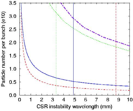
The above scaling analysis has been compared to numerical calculations for the NLC damping ring. The results are given in Fig. 6 where we plot the threshold particle number as a function of the CSR instability wavelength for (dashes), (solid) and (dots). In addition, the cutoff wavelength for the three cases is indicated with vertical lines using the same notation. Clearly, the threshold increases rapidly as is increased as expected. The approximately quadratic scaling given above is followed as is increased from the nominal value of 2.2 to 6.5 but the dependence is weaker as is decreased to 0 because of the change in the beam energy spread which was assumed constant. Based on these results a new version of the NLC damping ring has been designed with an which has a significantly higher threshold for both this CSR instability as well as the conventional microwave instability driven by the vacuum chamber impedance newNLCDR .
VI Discussion and conclusion
In this paper, we studied a possible beam instability due to coherent synchrotron radiation from dipole and wiggler magnets in a storage ring. This instability may be important in many high luminosity factories such as DAPHNE, PEP-II, KEK-B, and CESR-C as well as the damping rings of future linear colliders. We used the results to analyze the stability of the damping ring designs and found that a possible instability due to the CSR will exist in the NLC damping ring design and the ATF prototype damping ring at KEK. We then discuss optimization of the rings and the pros and cons of increasing the damping fraction due to the wigglers. This led to a redesign for the NLC damping which increases the threshold to more than four times the nominal charge per bunch.
As we discussed above, in our calculation, we used steady state impedance for both the dipoles and wigglers. In the future, it may be important to consider transient effects in our calculation. In addition, the shielding cutoff of the CSR should be calculated as part of the impedance and not treated as an ad hoc limit. This is also important because we assumed the same shielding cutoff around the ring but in practice it will differ in the bending magnets and the wigglers. Finally, the bunch length is the same order of the instability wavelength, while in the theory, we use a coasting beam model. In the future, the finite bunch length should be taken into consideration. All of these topics are under study and will be reported in a separate paper.
Acknowledgements.
The authors thank A.W. Chao, P. Emma, S.A. Heifets, M. Ross, M. Woodley of Stanford Linear Accelerator Center, S. Krinsky, J.B. Murphy, J.M. Wang of National Synchrotron Light Source, Brookhaven National Laboratory, and K.J. Kim of Advanced Photon Source, Argonne National Laboratory for many discussions. Work was supported by the U.S. Department of Energy under contract DE-AC03-76SF00515.Appendix A Growth rate at the FEL frequency and the odd harmonics
In this appendix, we discuss the growth rates calculated at the wiggler fundamental frequency, frequently refered to as the FEL frequency, and at the odd harmonics. The wiggler CSR long-range wakefield is WRS02
| (22) |
To the leading order in , this gives us the CSR impedance as
| (23) | |||||
where, is the Heaviside step function, i.e., for , , and for .
At the FEL frequency and the odd harmonics, the impedance has a logarithmically divergent imaginary part, Im, with , and the real part is finite. We write , where is the resistance and is the inductance, and . As a first estimate, we neglect the resistance and write only. In the dispersion relation Eq. (6), then . Now because of the factor , is huge compared with in the -nonvanishing integral region. Hence the integrand could be expanded. Keeping the first non-zero term, the integral is simplified as
| (24) |
for large to get
| (25) |
The upper (lower) sign in Eq. (25) refers to the case of a positive (negative) . For the rings which we study in this paper, they all have and we take the upper sign. Hence, Im, i.e., the growth rate will be zero and the system is stable at the FEL frequency and all the odd harmonics. This agrees with the conventional knowledge that a ring is stable with a purely inductive impedance and a positive momentum compaction or a purely capacitive impedance and a negative momentum compaction.
Appendix B Single wiggler
In this appendix, we study the beam instability in a single wiggler. From FEL theory, we would expect instability at the wiggler fundamental radiation frequency and all the harmonics. In addition, we need to look at a microwave-like low-frequency instability.
In a wiggler, the slippage factor is
| (26) |
i.e., the slippage factor is negative, therefore, we choose the lower () sign in Eq. (6). In Fig. 7, we plot the imaginary part of as a function of the instability wave number for the wigglers in the NLC and TESLA damping rings Andy02 ; Deck9901 . For the region where Im(), the beam is stable. We find that, for the nominal current, the system is stable within the entire interesting region where the perturbation wavelength cm, except at the wiggler fundamental radiation wavelength and the third harmonic.
In fact, according to Eq. (26), we have and we need take the lower sign in Eq. (25). When we approach the fundamental and the third harmonic frequency, becomes large, and Eq. (25) gives us a large Im(), i.e., a large growth rate as we find in Fig. 7. However, according to Eq. (25), we will have Im, where is the peak current of the electron bunch; while in the FEL theory, the growth rate scales as Im BPN84 . To correctly calculate the FEL instability from the wake impedance approach, the electron density distribution function has to be taken at the retarded time in the standard Vlasov equation SK03 . This then leads to a cubic dispersion relation same as in the FEL theory, and results in the cubic root scaling in the growth rate: Im.
Nevertheless, here we further use the FEL theory to study the instability at the FEL frequency and the third harmonic. We use the simulation code TDA TW89 to calculate the instability growth length at the fundamental frequency and a newly developed code JHW02 to calculate the instability at the third harmonic. The wiggler and beam parameters used are listed in Table 1. In the NLC damping wiggler, the growth length at the FEL frequency is about 50 m assuming that the phase errors between wiggler sections is small. Fortunately, the separation between the 2-meter long wiggler sections will further reduce the gain. In addition, any modulation that is induced at the fundamental wavelength of m will be smeared out by the energy spread and the momentum compaction as the beam is transported around the remainder of the ring. A similar conclusion is found for the TESLA damping ring wigglers and the instability at the FEL frequency and the odd harmonics are not expected to be a limitation in either case.
References
- (1) J.B. Murphy, S. Krinsky, and R.L. Gluckstern, Part. Accel. 57, 9 (1997); J.B. Murphy, S. Krinsky, and R.L. Gluckstern, in Proceedings of the 1995 IEEE Particle Accelerator Conference (IEEE, Piscataway, NJ, 1996), p. 2980; A. Faltens and L.J. Laslett, Part. Accel. 4, 152 (1973).
- (2) Ya.S. Derbenev et al., DESY Report No. DESY-TESLA-FEL-95-05, 1995.
- (3) R. Warnock, P. Morton, Part. Accel. 25, 113 (1990); R. Warnock, SLAC Report: SLAC-PUB-5417, 1991; SLAC-PUB-5523, 1991.
- (4) K.Y. Ng, Part. Accel. 25, 153 (1990).
- (5) H. Braun, F. Chautard, R. Corsini, T.O. Raubenheimer, P. Tenenbaum, Phys. Rev. Lett. 84, 658 (2000).
- (6) H. Braun, R. Corsini, L. Groening, F. Zhou, A. Kabel, T.O. Raubenheimer, R. Li, T. Limberg, Phys. Rev. ST Accel. Beams 3, 124402 (2000).
- (7) M. Hning, P. Piot and H. Schlarb, Nucl. Instrum. Meth. A 475, 348 (2001).
- (8) M. Borland and J. Lewellen, in Proceedings of the 2001 IEEE Particle Accelerator Conference (IEEE, Piscataway, NJ, 2002), p. 2839.
- (9) G. Stupakov, S. Heifets, Phys. Rev. ST Accel. Beams 5, 054402 (2002).
- (10) G. Vignola [DAPHNE project team Collaboration], LNF-91-037-R Presented at Workshop on Physics and Detectors for DAPHNE, Frascati, Italy, Apr 9-12, 1991.
- (11) PEP-II: An Asymmetric B-factory, SLAC-418 (1993).
- (12) KEK Report 95-7 (1995).
- (13) G. Dugan et al., in Proc. of the APS/DPF/DPB Summer Study on the Future of Particle Physics (Snowmass 2001) ed. N. Graf, eConf C010630, T201 (2001).
- (14) J. Wu, T.O. Raubenheimer, G.V. Stupakov, Phys. Rev. ST Accel. Beams 6, 040701 (2003).
- (15) E.L. Saldin, E.A. Schneidmiller, and M.V. Yurkov, Nucl. Instrum. Methods Phys. Res., Sect. A 417, 158 (1998).
- (16) A. Wolski, “NLC Damping Rings: Lattice Parameters, Information and Resources”, (URL: http://awolski.lbl.gov/nlcdrlattice/default.htm).
- (17) W. Decking, “Damping Ring Lattice Update”, talk given at the TTF Collaboration Meeting, DESY, 7-9 July 1999; “The TESLA Damping Ring”, talk given at the Snowmass 2001, July 2001.
- (18) http://www-jlc.kek.jp/atf/ATF.overview-e.html .
- (19) R. Bonifacio, C. Pellegrini, L. Narducci, Opt. Commun., 50, 373 (1984).
- (20) G. Stupakov and S. Krinsky, “Derivation of FEL gain using wakefield approach,” submitted to 2003 Part. Acc. Conference, Portland, Oregon (2003).
- (21) T.M. Tran, J.S. Wurtele, Comput. Phys. Commun. 54, 263 (1989).
- (22) J. Wu, “Harmonic contents of and detailed study on a High-Gain Harmonic Generation Free Electron Laser,” submitted to 2003 Part. Acc. Conference, Portland, Oregon (2003).
- (23) G.V. Stupakov, I.A. Kotelnikov, Phys. Rev. ST Accel. Beams 6, 034401 (2003).
- (24) M. Venturini, ”Wigglers and Single-Particle Dynamics in the NLC Damping Rings,” submitted to 2003 Part. Acc. Conference, Portland, Oregon (2003).
- (25) P. Emma, T. Raubenheimer, Phys. Rev. ST Accel. Beams 4, 021001 (2001).
- (26) A. Wolski et al., “A Lattice With Large Momentum Compaction for the NLC Main Damping Rings,” submitted to 2003 Part. Acc. Conference, Portland, Oregon (2003).