Selective nanomanipulation using optical forces
Abstract
We present a detailed theoretical study of the recent proposal for selective nanomanipulation of nanometric particles above a substrate using near-field optical forces [Chaumet et al. Phys. Rev. Lett. 88, 123601 (2002)]. Evanescent light scattering at the apex of an apertureless near-field probe is used to create an optical trap. The position of the trap is controlled on a nanometric scale via the probe and small objects can be selectively trapped and manipulated. We discuss the influence of the geometry of the particles and the probe on the efficiency of the trap. We also consider the influence of multiple scattering among the particles on the substrate and its effect on the robustness of the trap.
pacs:
PACS numbers: 03.50.De, 78.70.-g, 42.50.VkI Introduction
Thirty years ago, it was demonstrated by Ashkin that optical fields produce a net force on neutral particles. [1, 2] Since then it has been shown that it was possible to exploit the mechanical action of optical fields in a wide range of applications. From atomic and nonlinear physics to biology, optical forces have provided a convenient way to manipulate, non destructively, small particles in a liquid environment [3, 4, 5, 6]. These optical forces can also be used to create microstructures by optical binding, [7] or measure the van der Waals force between a dielectric wall and an atom. [8] But one of the most interesting applications of optical forces is the the optical tweezers. They have proved useful not only for trapping particles, but also for assembling objects ranging from microspheres to biological cells [9, 10] (notice that in Ref. [B 5] the trapped spheres are 50 times larger that the wavelength used in the experiment). More recently, optical tweezers have been used to transport Bose-Einstein condensates over large distance.[11] However, most of these manipulations involve objects whose size is of the order of one to several micrometers. While for much smaller objects, such as atoms or molecules, the scanning tunneling microscope provides a powerful tool for manipulation and engineering[12], dealing with neutral particles of a few nanometers requires new experimental approaches.
A novel approach was presented recently, where an apertureless near-field probe is used to create localized optical traps and allow for the selectively capture and manipulation of nanoparticles in vacuum or air above a substrate . [13] In this paper we analyze in detail the scheme presented in Ref. [13] and we discuss the interplay of the different physical processes that contribute to the force experienced by the particles (including van der Waals forces). The particles are not in a liquid environment, hence there is no Brownian motion (which would otherwise induce a disruptive force for small particles) and the apertureless probe can be used as a near-field optical probe to localize and select the particles [14, 15].
In Sec. II we describe briefly the method used to compute the optical forces. In Sec. III A we study the optical force experienced by a sphere in presence of a tungsten tip. First we explain the principle of the manipulation of a nano-object with the apertureless probe and then we look at the influence of the different parameters of the system, (geometry of the tip, size of the nanoparticle, illumination) on the trapping. In Sec. III B the presence of many particles on the substrate is investigated to study the influence of neighbors on the manipulation of a particle. Finally in Sec. IV we present our conclusions. In appendix A we underline the importance of using total internal reflection to get an efficient optical trap at the tip apex, and in appendix B we compare the optical force with the other forces present in this system (gravitational force, van der Waals force, electrostatic force, and capillary force).
II Computation of the optical forces
The theory used to compute the optical forces has been presented previously. [16]. We use the couple dipole method (CDM). Here we only recall the main steps. First, the coupled dipole method [17, 18] is used to derive the field inside the different objects (probe and particles). Each object is discretized into dipolar subunits and the field at each subunit satisfies the following self-consistent equation
| (1) | |||||
| (2) |
is the dynamic polarizability of subunit , [19], is the field linear response to a dipole in free space, [20, 21] and the field linear response to a dipole, in the presence of a substrate. [22, 23] Note that the field obtained in Eq.(1) takes into account all the multiple interactions between the particles, the substrate, and the tip. The second step is to derive the optical forces experienced by each subunit. Once the electric field is known, the component of the total force [24] on the th subunit is given by
| (3) |
where or , stand for either , or , and is the electric dipole moment of the th subunit. [25] Notice that the derivative of the field is obtained by differentiating Eq.(1). To compute the force exerted by the light on any given object, one has to sum the force experienced by each dipole forming the object. The main advantage of using the CDM to compute the optical force is that retardation and multiple scattering between the objects, the tip and the substrate are accounted for.
III Results
We consider a particle in glass, placed either in air or vacuum, with relative permittivity and a radius , above a dielectric substrate. The particle is illuminated by two evanescent waves created by total internal reflection at the substrate/air interface (angle of incidence with where is the relative permittivity of the substrate). The importance of illuminating the particle on the substrate with evanescent waves is explained in appendix A. The two evanescent waves are counterpropagating , i.e., , with the same polarization and a random phase relation (Fig.1). As discussed later, this is to ensure a symmetric lateral force. The optical trap is created by the interaction of the incident waves with a tungsten probe with a radius of curvature at the apex .

Notice that all forces are computed for an irradiance of 0.05 W/m2, which correspond, for a laser with a power of 5 W, to a beam focused over an area of 100 m2.
A isolated particle
1 principle of the manipulation
In order to foster understanding of the selective trapping scheme, we start by studying the interaction between a single sphere with radius nm, and a tungsten tip ( a tip often used in apertureless microscopy as they are not expensive and easy to prepare) with a radius at the apex 10 nm, which is a typical size for tips used in experiments. The illumination wavelength is nm. Figure 2 shows the component of the force experienced by the sphere versus the vertical position of the tip above the sphere, for both TE and TM polarizations. The illumination angle is close to the critical angle, . As the tip gets closer to the sphere, the evolution of the force is radically different for the two polarizations. The sphere experiences mainly three gradient forces (because the sphere is small, the scattering force is negligible, and since the relative permittivity is real, absorption does not contribute to the force). The three forces are: first, the negative gradient force due to the evanescent incident field (notice that for a dielectric sphere, the gradient force always pushes the sphere toward the region of high field intensity, as the evanescent field decays in the direction of positive, the gradient force is negative), second, the negative gradient force due to the interaction of the sphere with itself via the substrate (this force can be understood as the interaction between the dipole associated to the sphere and the field at the dipole location, radiated by this dipole and reflected by the surface; this force is always negative whatever the dielectric constant of the sphere[16]), and third, the gradient force resulting from the interaction between the probe and the sphere. This last gradient force can be either positive or negative. For TM illumination, there is a large enhancement of the field near the apex of the probe due to the discontinuity across the air/tungsten boundary [26]. This enhancement generates a positive gradient force which, at short distances, counterbalances the two negative contributions (due to the interaction of the particle with itself via the substrate, and the incident evanescent waves). The inset in Fig. 2a shows that the force experienced by the sphere changes sign when the tip is 25 nm away from the sphere. On the other hand, for TE polarization (Fig. 2b), as the tip gets closer to the particle, the magnitude of the component of the force increases while the force remains negative (directed toward the substrate and away from the tip), hence preventing any trapping. This due to a decrease of the field at the tip apex for this polarization (one can see the electromagnetic field around a gold tip apex in Ref.[B 5]), thus giving a third negative contribution to the gradient force. Because the apex of the tip and the sphere are small compared to the wavelength, the nature of the interaction between the tip and the sphere can be understood by considering the tip and the sphere as two dipoles. In TM polarization, these two dipoles have two components, parallel and perpendicular to the substrate. As shown in Ref.[B 5] two aligned dipoles tend to attract each other and two parallel dipoles tend to repel each other. For the same magnitude of the two components (parallel and perpendicular) the attractive force due to the component perpendicular to the substrate is twice that of the repulsive force due to the parallel component. Hence in TM polarization the sphere is attracted by the tip. For the TE polarization however, the two dipoles are essentially parallel to the substrate and the sphere experiences a negative gradient force. Notice that if we only use a single laser beam, a lateral force would appear as shown in Fig. 3. For TE polarization, the lateral force is very small (in the fN range) and negative showing that it is mainly due to the gradient force arising from the presence of the tip (the radiation pressure from the incident field always gives a force in the direction of the wave vector, hence in this case a positive force). When the sphere is in contact with the substrate, the lateral force ( component) is weaker than the component of the force by a factor 40. As the static friction coefficient is one (glass on glass), the sphere cannot slide along the surface. Indeed, as shown by Kawata and Sugiura, [28] for the sphere to slide on the substrate, its radius has to be large enough for radiation pressure to overcome the gradient force. For TM polarization the lateral force may have a disruptive effect as it tends to push the sphere away from the tip, particularly when becomes positive. In order to avoid this problem, we introduce a second, counterpropagating, evanescent wave with a random phase relation with respect to the first wave. In this way, the sphere experiences no lateral force when it is right underneath the tip. Note that due to the coherence time of the laser (e.g. 200 ps for an Argon laser), one can suspect that the sphere experiences spatial fluctuations. We compute these spatial fluctuations for a glass sphere with a radius nm, trapped by an optical force pN. From the second law of Newton the distance covered by the sphere, during the time of coherence, is equal to pm. Therefore, in any realistic configuration, the trapped particle will only be sensitive to the time-averaged trapping potential, without actually being perturbed by the laser fluctuations. If the sphere is larger, its sensitivity to the spatial fluctuation becomes even smaller due to its larger weight.


To assess fully the probe-particle coupling we need to study the evolution of the force experienced by the particle, as the probe is moved laterally. The coordinates represent the lateral position of the sphere. The tip is at (0,0) (see Fig. 4a). Figure 4 shows the component of the force when the tip is 25 nm above the substrate, for TE and TM polarizations, and for an angle of incidence . For TM polarization, Fig. 4b represents the magnitude of the component of the force.
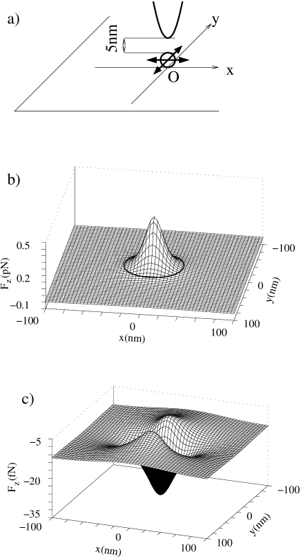
We see that when the tip is far from the particle the force is negative: the sphere does not feel the tip. As the tip gets closer, the particle starts to experience a positive force along . The change of sign of the component of the force occurs when the sphere is about 30 nm away laterally from the tip. Below this distance the sphere is in the area of the enhancement of the field at the tip apex and the gradient force changes sign, hence the sphere is attracted toward the tip. The region where is represented by a solid closed curve in Fig.4b.

If the tip is farther away from the substrate, the zero force curve becomes smaller because of the dependence of the force on the tip-surface distance (Fig. 2). If we approximate the zero force curve by a circle, the radius of the circle is about 7 nm when the tip is 31 nm above the substrate (and as shown by Fig.2 it vanishes when the tip is 45 nm above the substrate). Figure 4c, which pertains to TE polarization, shows that the component of the force is always negative and smaller in magnitude by a factor 100 than the force associated to the TM polarization. Note that the force becomes stronger (more negative) when the sphere gets closer the tip. Figure 5 represents the lateral force () experienced by the sphere when the tip scans the surface (the arrows represent the direction of the force experienced by the sphere at the origin of the arrow, and the length of the arrows shows the magnitude of this force). We only consider an area of 40 nm around the origin as the lateral force decreases very quickly away from the tip. In Fig. 5a, the vectors show that the sphere is attracted by the tip, hence the lateral force pushes the sphere toward the tip. Therefore, when the tip and the particle are close enough to each other for the component of the force to be positive (the zero force, is always represented by the black circle), and large enough to lift the particle off the surface, the lateral force actually helps bringing the particle in the trap. This effect is due to the symmetric illumination. Again TE polarization gives a different result. Figure 5b shows that the lateral force pushes the particle away from the tip. However, since the magnitude of the (downward) component of the force is larger than the component by a factor of 5, we expect that the sphere is not displaced when the tip is scanned over it under TE illumination. Note that apertureless probes are often used in tapping mode when imaging a surface. This mode minimizes the lateral motion imparted to the object by the optical force.
We have shown that a tungsten probe can be used to trap efficiently a nanometric object above a surface using TM illumination. For nanomanipulation purposes it is important to assess the stability of the trap as the probe lifts the particle off the substrate. Figure 6 shows the component of the force when the sphere is located at the apex of the tip and the tip is moved vertically. For the TM polarization (Fig. 6a) the optical force remains positive over a large distance, at least 200 nm. The particle can therefore be manipulated vertically as well as horizontally. The stability of the trap when the tip-particle pair is away from the substrate prevents any disruptive interaction with the surface roughness as shown in the next section. Note that the evolution of the force versus the distance to the substrate is linear rather than exponential. The particle experiences a negative gradient force due the exponential decay of the intensity of the illumination. At the same time, the particle experiences a positive gradient force due to the field enhancement at the tip apex, which also decreases exponentially with because this enhancement depends on the intensity of the evanescent illuminating light. The competition between these two contributions results in a weak decrease of the trapping force as the particle is moved away from the substrate.

As described in [13], the procedure to trap a small object with a tungsten tip is the following: first TE illumination is used while the tip scans the surface in tapping mode or in constant-height mode if the area under investigation is small enough. Such modes avoid the displacement of the particle by the tip. Once an object has been selected, the probe is placed above the object and the polarization of the illumination is rotated to TM. The probe is then brought down over the particle and captures it. The probe can then move the particle above the substrate, both horizontally and vertically, to a new position (note that if, for some reason, one wishes to move the particle over distances larger than the size of the illumination spot, one could move the sample with a piezoelectric device once the sphere is trapped at the apex of the tip). As shown by Fig. 6b, as the component of the force in TE polarization is always negative, the nanoparticle can be released by switching back to TE polarization. The lack of trapping under TE illumination is actually an important advantage during both the imaging (selection) and release phases of the manipulation. Indeed, under TE illumination, when the tip is above a particle, it actually increases the downward optical force, which contributes to prevent the tip from sweeping the particle away.
2 Efficiency of the manipulation scheme
In the previous section we have established the possibility to manipulate selectively a nanoparticle above a flat dielectric substrate. Now we study the influence of the different parameters of the system (tip radius at the apex, angle of incidence, etc) on the efficiency of the trap.
a Influence of the illumination
So far we have considered an angle of incidence of 43 degrees, which corresponds to a slow decay of the evanescent field above the substrate.
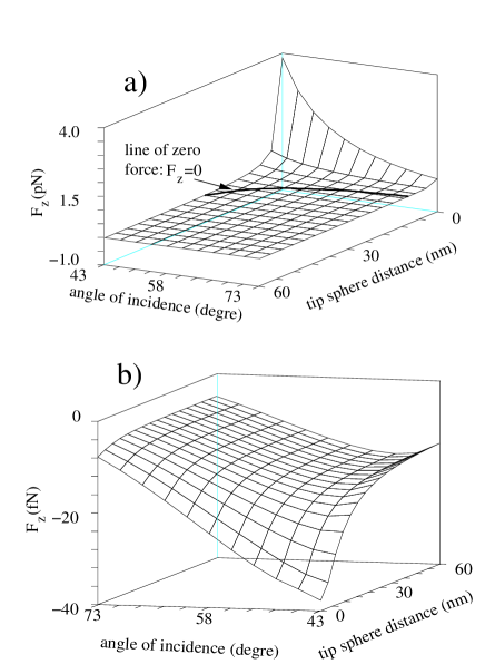
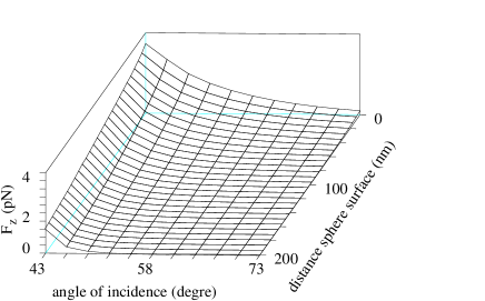
Figures 7 and 8 show the influence of the angle of incidence on the capability of the tip to manipulate the nano-object. Figure 7 shows the evolution of the component of the force as the tip gets closer the surface, versus the angle of incidence for both polarizations. In Fig.7a (TM polarization) one can see that for a fixed distance between the tip and the substrate, the larger the angle of incidence, the smaller the magnitude of the force experienced by the trapped object. Note that as the angle of incidence increases, the initial (evanescent) field decays faster. Accordingly, a weaker field reaches the tip and the enhancement of the field at the tip apex is less important leading to a smaller positive gradient force. As a consequence, when the tip approaches the sphere, the change of sign for the component of the force occurs for smaller tip-sphere distances at larger angles of incidence (Cf. the thick line on Fig. 7a which represents the level curve ). For example for , =25 nm and for , =8 nm. This means that it is easier to manipulate the sphere when the angle of incidence is close to the critical angle. Notice that for TE polarization (Fig. 7b), when the angle of incidence increases, the magnitude of the negative force decreases. The explanation for this evolution is similar to that of the TM polarization case: the incident field that reaches the apex of the tip is weaker for large angles of incidence. Accordingly, the interaction between the tip and the particle becomes weaker as the angle increases, and the magnitude of the repulsive force decreases. Figure 8 represents the force experienced by the sphere when it is located at the apex of the tip, versus the angle of incidence and the distance between the trapped sphere and the substrate. The force along decays more rapidly for larger angles of incidence. The exponential decay of the incident field is stronger when the angle of incidence is far from the critical angle. As the positive force along is due to the enhancement of the field at the apex of the tip and it depends on the value of the incident evanescent field at the tip apex, the component of the force follows the same behavior as the incident field. Note that the influence of the wavelength is easy to infer. The initial field decays as with , where is the wavelength in vacuum. When increases, decreases, hence the exponential decay is slower and the manipulation is easier to perform.
b Influence of the geometry
In the previous section, both the radius of the tip , and the radius of the sphere were 10 nm. In this paragraph we study the influence of these two geometrical parameters. Figure 9 shows the evolution of the force along versus , for both polarizations, and two angles of incidence. The tip (=10 nm) is in contact with the sphere. One might expect a force proportional to as the gradient force is proportional to the real part of the polarizability, hence to the volume of the sphere. Actually, this behavior is only observed for the TE polarization (Fig. 9b). For the TM polarization, when increases, so does the distance between the tip and the substrate. Thus we have a competition between the increase of the gradient force due to a larger and the decrease of the field enhancement at the tip apex due to a larger distance between the tip and the substrate. For the smallest angle (), because the decrease of the field is slow, the force starts by increasing linearly for small values of . When increases, the enhancement of the field at the tip decreases and the positive gradient force due to this enhancement vanishes. The competition between these two effects leads to a maximum of the force for =40 nm. For the largest angle () the incident field decays rapidly in that case, and for larger than 40 nm the force experienced by the sphere becomes negative. Thus it would not be possible to manipulate a larger particle. For TE polarization the component of the force varies roughly as . This implies that the main contribution to the force is due to the incident field: the tip has a very weak influence on the force experienced by the sphere. To check this argument we plot the force along without the presence of the tip (line with the “+” symbol in fig9.b).

These curves show that for the largest angle () the above argument is true, only when the radius is small we can see a slight shift of the force due to the presence of the tip (see inset in fig.9b). For the smallest angle () the presence of the tip shifts the force curves toward negative values, as explained in the previous section. This holds even for a very large radius of the sphere because of the slow evanescence of the incident field.
We must now check that for large radii it is always possible to manipulate the sphere above the substrate. Figure 10 shows the component of the force at two different angles of incidence for two different radii: 30 nm and 50 nm. One can see that it is possible to lift the spheres up to 200 nm above the surface without any problem, even for the case with nm which corresponds to a radius close to the limiting case (Fig. 9a shows for nm if ). In that case, the force is small and the trap is less robust than for smaller angles of illumination. Therefore, the trapping scheme presented here works over a wide range of particle sizes. Notice that although we could not compute the largest radius that we could manipulate at because it would require too many subunits, we can estimate that spheres with a radius up to around 90 nm can be trapped and manipulated.

Another relevant geometric parameter is the radius of curvature at the apex of the tip. It is easy to see the importance of this parameter for our optical trap because the enhancement of the field at the tip apex depends directly on this radius. Figure 11 shows the component of the force versus , for a particle with radius 10 nm, for two different angles of incidence. One can see that the component of the force depends strongly on the radius of the tip apex. For the squares are the CDM results and show a decay of the force for larger radii. The solid line is a fit of the form where and are the parameters of the fit. This form is associated to the dependence of the force, which is found irrespective of the angle of incidence (see circles on Fig. 11).

B Many particles on the surface
In the preceding section we studied the case of an isolated sphere to illustrate how to select and manipulate a nano-object above a surface. It is nevertheless important to know whether the proposed manipulation scheme would still work if several particles are clustered together. We consider a set of three spheres (radius 10 nm, permittivity 2.25) aligned along the axis. The probe is placed above the middle sphere. We account for the multiple scattering between the three spheres, the substrate, and the tip. The optical binding induced among the spheres [27] is also included in our description. For this configuration again, TE illumination does not permit trapping. For TM illumination, we plot in Fig. 12 the component of the force experienced by the middle sphere and by those on the sides as a function of the vertical distance between the probe and the middle sphere. For an angle of incidence , as the tip gets closer to the middle sphere, the component of the force, although the strongest for the middle sphere, remains positive for the two side spheres. This could be a problem if one wanted to manipulate only one particle among several. The central particle can be selectively trapped by increasing the angle of incidence of the illuminating beams to tighten the trap in the direction. In Fig. 12 we see that for the optical force induced by the probe is positive only for the middle sphere. This remains true for three spheres aligned along . Figure 13 shows the extraction of the middle sphere by the tip. Our calculation shows that the vertical force experienced by the two side spheres remains negative when the probe moves away from the substrate for the angle of incidence . Therefore, the spheres on the sides do not hinder the capture of the middle sphere if the angle of incidence is adequately chosen.


Notice that this computation is done for three identical spheres. We show in Fig. 14 that if the middle sphere is larger than the other two, it is still possible to trap the middle sphere without disturbing the side spheres. Figure 14a shows the component of the force experienced by the middle sphere for three different radii: =10, 17, and 28 nm. The side spheres have a fixed radius: 10 nm. When the middle sphere is lifted off the surface by the tip (angle of incidence ) the force along is always positive, hence the manipulation of the middle sphere is not disturbed by the side spheres. Figure 14b shows the evolution of the force experienced by the sides spheres during the extraction of the middle sphere. This force is always negative, therefore the side spheres are not attracted by the tip. Moreover, as the radius of the middle sphere increases, the component of the force becomes larger while being negative, thus excluding the possibility of having the side spheres captured by the tip. This reflects the fact that as the radius of the middle sphere increases, so does the distance between the side spheres and the apex of the tip. Hence as the tip is farther from the sides sphere its influence is weaker.

In Fig. 15 we present the case where the middle sphere is smaller than the side spheres. First for an angle of incidence close to the critical angle () the three spheres experience a positive force when the tips approaches the substrate. If we look carefully (see the inset), we see that the component of the force becomes positive for the side spheres before the middle sphere experiences a positive force. Hence it is impossible to only manipulate the middle sphere. If the angle of incidence is increased to the value to make the trap smaller, we show that the component of the force becomes positive for the middle sphere first. However, when the tip is in contact with the middle sphere the force is positive for all three spheres. Notice that to get a smaller trap one can increase the angle of incidence but in that case the force would be very small compare to the other force in the system (see appendix A and B). Therefore, in this case it is impossible to capture selectively the middle sphere. The solution would be to first move the side spheres aways to isolate the smaller middle sphere, and only after would it be possible to trap it. Notice that when the tip is far from the surface the negative force is stronger for the largest spheres. This is due to the gradient force proportional to .

In the previous section we showed that a tungsten probe can be used to trap efficiently a nanometric object above a surface using TM illumination. By moving the tip laterally, it is possible to transport the selected particle in a precise manner. However, we must check that the electromagnetic field scattered by another particle on the substrate would not disturb the trap during the transport. Figure 16 shows the evolution of the force experienced by the sphere trapped by the tip when a second sphere is on the surface as show by Fig. 16a (both spheres have a radius of 10 nm). Figure 16b shows that the component of the force on the trapped sphere is not altered by the presence of the other sphere. When the two spheres are 30 nm apart ( nm), the force along does not depend on the position of the tip. Figure 16c shows that the lateral force is more sensitive and we can see some oscillations when the two spheres are close to each other. However, this is not really a problem since even if the two spheres are only 30 nm apart, the lateral force is a thousand times smaller that the force along , and therefore, would not hinder the optical trapping. We have studied the case where the tip and the trapped sphere scan the surface at nm. When the tip is located at the origin, the two spheres are in contact (the trapped sphere and the sphere on the substrate) and the component of the force becomes negative, of the order of -5 pN, and the lateral force when the spheres are close to each other is about 1 pN. In this configuration the trapped sphere can escape and thus be lost by the tip. In summary, if the distance between the two spheres is larger than three times the radius of the sphere on the surface, then the trapped sphere is not disturbed.

IV conclusion
We have presented a detailed study of a trapping scheme that allows one to trap and nanomanipulate, in a selective manner, nanometric particles in air above a substrate. The substrate is illuminated under total internal reflection by two laser beams which create two counter-propagating evanescent waves. An apertureless tungsten probe is used to scatter these two waves and generate a localized optical trap. An object of a few nanometers can be selectively brought into the trap and manipulated with the probe. An important advantage of this scheme is the possibility to use the probe to localize the particles upon the surface. Using TE polarization the tip can scan the surface in tapping mode or constant-height mode, and allow one to acquire an optical near-field image of the surface. Because in TE polarization the component of the optical force is directed toward the substrate, there is no risk of displacing the particles during the imaging phase. Then, just by switching to TM polarization, we can manipulate the particles. As we showed, even if many particles are clustered, varying the angle of incidence still makes it possible to manipulate selectively only one particle.
An interesting extension of this work will be a study of the influence of different illuminations (e.g. focused beam), and the study when the particle is either absorbing or metallic. In that case the optical force has two contributions: the gradient force and the momentum transfer from the laser to the particle due to absorption. For metallic particles, the strong spectral dependence of the electromagnetic response (or the resonances in the response of dielectric and metallic particles) could lead to new effects. For example at some wavelength the gradient force on a silver particle vanishes, and only the absorbing force remains. Such phenomena could lead to a material selective trapping. It will also be interesting to explore the possibility of trapping a small gold particle, a few nanometers in size, and use it as a highly localized probe for topographic or spectroscopic studies [29, 30].
A Importance of the evanescent illumination
In this appendix we show that the choice of total internal reflection illumination is the most adequate to get a strong optical force. Figure 17 shows the component of the force when the angle of incidence is varied between 0 and 90 degrees for an illumination either from above or from below the surface. For an illumination from below the surface (internal reflection), and for TM polarization, the largest force is obtained for . The magnitude of the force decreases exponentially when increases. For smaller than the critical angle, the force is small and even negligible for smaller than 20 degrees. For TE polarization the minimum of the component of the force is obtained for . This negative force is important as it prevents the tip from displacing the particle during scans. If the surface is illuminated from above, for TM polarization the components of the force remains weaker that the force obtained with an evanescent wave, and for TE polarization the negative force is very weak compared to those obtained with an evanescent wave above the surface. Hence to trap and manipulate a nano-object it is best to choose an angle of incidence close to but larger than the critical angle.

B Discussion on the role of forces other than the optical force
In an actual experiment, there would be other forces attracting the sphere toward the substrate. These forces are mainly four: van der Waals, electrostatic, capillary, and gravitational forces. One must therefore compare their effect with that of the optical forces in order to assess the robustness of the scheme.
1 The van der Waals force
The van der Waals force [31] between two particles (which is the Casimir force in the nonretarded case [32]) can be described as a short range force, derived from the Lennard-Jones 6-12 potential, in the form
| (B1) |
being the distance between the two particles, the Hamaker constant ( zJ for glass, and about 200 zJ for tungsten), corresponds to the separation of lowest energy between two particles (i.e. the position of the minimum of the Lennard-Jones potential) that we have estimated at 0.5 nm, and is the Derjaguin geometrical factor related to the mutual curvature of the two particles. Notice that the van der Waals force is maximum when .
If we compute the van der Waals force between the glass sphere and the glass surface we have ( radius of the sphere), hence the force is pN. This force is not a problem as the optical force when the tip is in contact with the sphere is larger than 1 pN. In addition we have to consider the van der Waals force between the apex of the tip and the sphere when they are in contact. We have estimated it for the case where the radius of the sphere and the curvature of the tip apex are equal to 10 nm, with nm, zJ, for which we obtain pN. Hence the two van der Waals forces are of comparable magnitude and cancel each other out when the particle is in contact with both the substrate and the tip. Therefore the van der Waals force does not hamper the manipulation of the particle. A problem can arise when we want to release the sphere from the trap, as switching back to TE polarization may not create a strong enough repulsive force. There are many ways to avoid this problem. One is to approach the tip-sphere system to the surface to benefit from the van der Waals force between the substrate and the sphere. Another solution is to choose an angle of incidence close to the critical angle to increase the magnitude of the repulsive force. Of course, one could also increase the intensity of the incident field.
Notice that the van der Waals force is computed here for perfectly smooth bodies. In reality this force should be weaker. Indeed, for a surface roughness about 2 nm, the van der Waals force is reduced by a factor of 10. [33]
2 The electrostatic force
The electrostatic force (Coulomb force) between an electrically charged sphere and an uncharged plane can be expressed as [33]
| (B2) |
being the charge surface density ( Cm-2 in very dry conditions), Fm-1 the permittivity of vacuum, and the relative permittivity of the dielectric substrate. For nm and , we get pN. This force is clearly negligible compared to the optical force. And moreover this force will be weaker for a conductor. [33]
3 The capillary force
If there is water on the surface, there will be a capillary force which can be expressed as [33]
| (B3) |
being the surface tension of water. With Nm-1. For a radius of the sphere nm we get pN. This force is of the same order as the optical force hence it is necessary to work in a dry environment in order to reduce this capillary force.
4 The gravitational force
The force of gravity is
| (B4) |
where ms-2 is the gravitational acceleration and kgm-3 is the density of glass. If the radius is equal to 10 nm we find aN, and the component of the optical force experienced by the sphere is larger (by a factor ) than the gravitational force. Hence gravity can be neglected.
5 Conclusion
In conclusion, in a dry environment (no capillary force) only the van der Waals force could perturb the release of the particle but as we mentioned previously, this force becomes weaker when roughness is taken into account. Note, however, that these four forces do not depend of the illumination whereas the optical forces depends of the intensity of the incident field. Therefore, one solution to avoid any disruptive contribution from the van der Waals force is to increase the power of the laser beam. For example, with the power used by Okamoto and Kawata [34], which corresponds to an irradiance of 0.2 W/m2, the optical force is multiplied by a factor 4 compared to the computation presented in this manuscript. Another way of increasing the optical force is to choose another material for the probe. For example, at a wavelength of 450 nm, a silver tip when in contact with the sphere, generates an optical force six times stronger than that created by a tungsten tip at nm.
REFERENCES
- [1] A. Ashkin, Phys, Rev. Lett. 24, 156 (1970).
- [2] A. Ashkin, Phys. Rev. Lett. 25, 1321 (1970).
- [3] A. Ashkin, J. M. Dziedzic, J. E. Bjorkholm, and S. Chu, Opt. Lett. 11, 288 (1986).
- [4] A. Ashkin, J. M. Dziedzic, and T. Yamane, Nature 330, 769 (1987).
- [5] S. M. Block, D. F. Blair, and H. C. Berg, Nature 338, 514 (1989).
- [6] A. Ashkin, Proc. Natl. Acad. Sci. USA 94, 4853 (1997).
- [7] M. Burns, J.-M Fournier, and J. Golovchenko, Phys. Rev. Lett. 63, 1233 (1989).
- [8] A. Landragin, J.-Y. Courtois, G. Labeyrie, N. Vansteenkiste, C. I. Westbrook, and A. Aspect, Phys. Rev. Lett. 77, 1464 (1996).
- [9] R. Holmlin, M. Schiavoni, C. Chen, S. Smith, M. Prentiss, and G. Whitesides, Angew. Chem. Int. Ed. 39, 3503, (2000); E. R. Dufresne, G. C. Spalding, M. T. Dearing, S. A. Sheets, and D. G. Grier, Rev. Sci. Inst. 72, 1810 (2001). E. R. Dufresne and David G. Grier, Rev. Sci. Instr. 69, 1974 (1998).
- [10] M. P. Macdonald, L. Paterson, K. Volke-Sepulveda, J. Arlt, W. Sibbet, K. Dholakia, Science 296, 1101 (2002).
- [11] T. L. Gustavson, A. P. Chikkatur, A. E. Leanhardt, A. Görlitz, S. Gupta, D. E. Pritchard, and W. Ketterle, Phys. Rev. Lett. 88, 020401 (2002).
- [12] S. Hla, L. Bartels, G. Meyer, and K. Rieder, Phys. Rev. Lett. 85, 2777 (2000); T. W. Fishlock, A. Oral, R. G. Edgell, and J. B. Pethica, Nature 404, 743 (2000); H. C. Manoharan, C. P. Lutz, and D. M. Eigler, Nature, 403, 512 (2000).
- [13] P. C. Chaumet, A. Rahmani, and M. Nieto-vesperinas, Phys. Rev. Lett. 88, 123601 (2002).
- [14] F. Zenhausern, Y. Martin, and H. K. Wickramasinghe, Science 269, 1083 (1995); R. Bachelot, P. Gleyzes, and A. C. Boccara, Opt. Lett. 20, 1924 (1995).
- [15] F. de Fornel, Evanescent Waves, Springer series in Optical Sciences, vol.73 (Springer Verlag, Berlin, 2001).
- [16] P. C. Chaumet, and M. Nieto-Vesperinas, Phys. Rev. B. 61, 14119 (2000); 62, 11185 (2000)
- [17] Purcell, and Pennypacker, Astrophys. J. 186, 705 (1973).
- [18] P. C. Chaumet, A. Rahmani, F. de Fornel, and J.-P Dufour, Phys. Rev B 58, 2310 (1998).
- [19] B. T. Draine, Astrophys. J. 333, 848 (1988).
- [20] J. D. Jackson, Classical Electrodynamics, 2nd ed. (John Wiley, New York, 1975), p395.
- [21] A. Rahmani and G. W. Bryant, Opt. Lett. 25, 433 (2000).
- [22] G. S. Agarwal, Phys. Rev. A 11, 230 (1975); 12, 1475 (1975).
- [23] A. Rahmani, P. C. Chaumet, and F. de Fornel, Phys. Rev A 63, 023819 (2001).
- [24] In fact the optical force is the time averaged force as shown in Ref.[B 5].
- [25] P. C. Chaumet, and M. Nieto-Vesperinas, Opt. Lett. 25, 1065 (2000).
- [26] L. Novotny, R. X. Bian, and X. Sunney Xie, Phys. Rev. Lett. 79, 645 (1997).
- [27] P. C. Chaumet, and M. Nieto-Vesperinas, Phys. Rev. B. 64, 035422 (2001).
- [28] S. Kawata, and T. Sugiura, Opt. Lett. 17, 772 (1992).
- [29] O. Sqalli, M.P. Bernal, P. Hoffmann, and F. Marquis-Weible, Appl. Phys. Lett. 76, 2134 (2000).
- [30] T. Kalkbrenner, M. Ramstein, J. Mlynek, and V. Sandoghdar, J. Microsc. 202, 72 (2001).
- [31] A. Feiler, I. Larson, P. Jenkins, and P. Attard, Langmuir, 16, 10269 (2000).
- [32] H. B. G. Casmir, and D. Polder, Phys. Rev. 73, 360 (1948).
- [33] F. Arai, IEEE/RSJ Conf. on Intell. Robots and systems, vol 2:236, Pittsburgh, PA, 1995.
- [34] K. Okamoto and S. Kawata, Phys. Rev. Lett. 83, 4534 (1999).