FEATHER:
a fast intra-pulse feedback system for the JLC.
Ground motion at the Future JLC detector may affect beam alignment and cause huge luminosity loss. The FEATHER (FEedback AT High Energy Requirements) project addresses this problem by designing a fast intra-pulse feedback system that will correct the observed beam offset.
1 Need for a fast feedback system
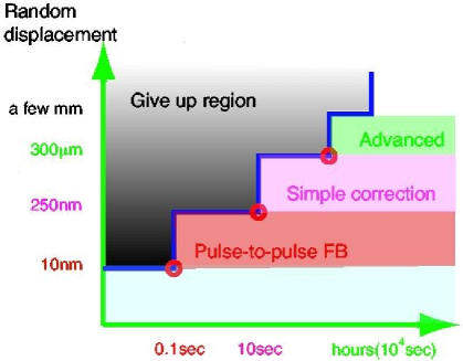
Ground motion arises from both natural and human activities. At frequencies higher than a few tens of hertz most of the motion comes from “cultural noise” (ie. human activities). At these frequencies the amplitude of the ground motion, a few nanometers, is comparable to the vertical beam size proposed for the JLC. This means that beams may be misaligned, leading to loss of luminosity (see figure 1) and poorer performances for the collider. The effects of beam misalignment have been studied using CAIN [Chen:1995jt].
![[Uncaptioned image]](/html/physics/0305017/assets/x1.png)
|
Figure 1: Fraction of the total luminosity lost as a function of the vertical offset of the beams at the interaction point. The horizontal unit, , is the vertical size of the beam (a few nanometers). |
This problem will partly be addressed during the site selection (see [uchida]) but it is unavoidable that some noise will remain (at least the noise arising from the accelerator operation). The figure 2 shows the acceptable noise amplitude for various frequency range.
Ground motion will also be reduced by various mechanical device, but in the high frequency region, an active device is needed to completely correct the beam misalignment. This is the purpose of the fast feedback system proposed by the FEATHER (FEedback AT High Energy Requirement) collaboration [feather].
2 Different models of fast feedback system
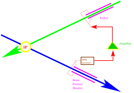
As the beam travels at the speed of the light, it is not possible to use the position of a bunch to correct the same beam. Furthermore, the beam size is of the order of a few nanometers, and most displacements are well beyond the reach of current Beam Position Monitors (BPM). But after the interaction point (IP) both beams are deflected with a deflection angle defined by their misalignment (see figure 3). Thus it is easier to measure the misalignment on the outgoing beam after the IP to correct the incoming beam. This can be done either on only one arm or on the two arms of the collider. The two arms solution reduces the correction required but is more complicated as good and fast communication between the two systems is required to avoid “opposite” corrections.
![[Uncaptioned image]](/html/physics/0305017/assets/x3.png)
|
Figure 3: Relation between the incoming offset and the deflected angle after the IP. |
2.1 Simple model of feedback
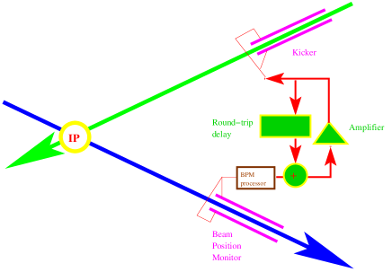
A simple system of feedback just needs to read the outgoing beam position from the BPM, compute the correction needed and then apply it to the incoming beam with a kicker. The layout of such system can be seen on figure 4.
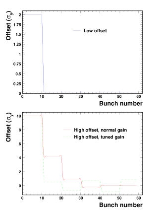
Earlier studies of simple model of feedback have been done in 1999 [Schulte:1999jn, Schulte:2000ax]. These studies used a kicker with a slow rise time (ie. high capacity), different from what is usually used at KEK. The beam offset as a function of the bunch number as calculated in these studies can be seen on figure 5.
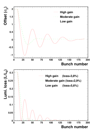
As the kicker will have a slow rise time there will be an initial rising period during which the kicker can not fully correct the beam offset. With a high gain (red line), when full correction is achieved, the beam reaching the BPM is still not fully corrected and thus the system will “overcorrect” the beam position, leading to oscillations as seen on figure 5. This can be avoided by lowering the gain of the correcting device, overcorrection will then be avoided but converging time will be much slower (blue dotted line). An average solution minimizing the luminosity loss is to use a moderate gain that will lead to a small overcorrection (green dashed line).
This is modified if a fast rise time kicker (as those available at KEK) is used. The figure 6 shows the beam offset as a function of the bunch number in that case.
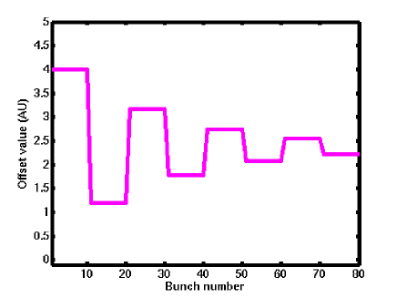
Now, we can see that once the first bunches reach the BPM, correction is applied to the beam to reduce its offset. But when the corrected bunches (with a small offset) reach the BPM, the correction applied becomes small (or even 0 if the bunches are fully corrected). The system will then oscillate between high and low correction state. If the gain applied is lower than 1, the system will eventually converge to an equilibrium state different from the full correction state.
Animations showing the behavior of this model with these 2 kinds of kicker can be seen on the FEATHER website [feather].
2.2 Delayed model of feedback
To avoid the oscillations featured by the “simple model”, a “memory” can be added so that when corrected bunches reach the BPM, the previously applied correction is remembered and can be again applied.
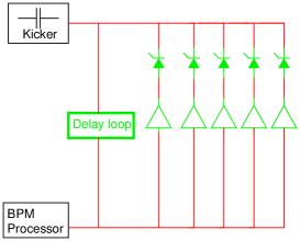
The memory needs to remember the correction applied around 10 bunches ago, which means keeping the information just during a few tens of nanoseconds. This can be done simply by adding a long wire in the circuit as a “delay” loop (see figure 7). The beam position as a function of the bunch number can be seen on figure 8.
In this delayed feedback, once the corrected bunches reach the BPM, the delay loop brings the information on the previously applied correction, avoiding the oscillations previously observed. But the choice of the correction to be applied as function of a given offset will trigger another problem as the relation between the position measured and the beam offset is non linear. If the correction is tuned for low offsets the high offsets will be undercorrected (red line on the bottom plot of figure 8). On the other hand, tuning the system for high offsets would lead to overcorrection and oscillations at low offset (dashed green line on the bottom plot of figure 8).
2.3 Improved model of feedback
The delayed model of feedback system can be further improved to suppress the problem arising from the non linearities by fitting lines on the figure 3 showing the relation between offset and deflection angle. This fit is shown on figure 9. It can be realized with an array of non linear components starting to operate at a different threshold as shown on figure 10.
![[Uncaptioned image]](/html/physics/0305017/assets/x9.png)
|
Figure 9: Fit (in blue, dotted line) of the simulated values (in red, plain line) of the deflected angle as function of the vertical beam offset at the IP. |
3 Bench and beam tests
3.1 Feasibility of the 3 models
The plots shown in the previous section have been made using numerical simulations in Perl (and later cross-checked with Matlab). It has not yet been possible to test these models in real beam conditions, however, the technical feasibility of these circuits has been checked on a test bench using a pulse generator.
3.1.1 Simple feedback
As the simple model of feedback just computes a correction from a given position, its electronic layout is fairly simple: as shown on figure 11 it should consist simply of an amplifier whose gain is adjusted to the required correction. As tunable amplifier are not easily available on the market, it is easier to amplify more than needed and then tune the gain with well chosen attenuators as shown on figure 12. On that figure, the device used to merge the signal from the BPM antenna and to split it to both kicker strips is also shown.
![[Uncaptioned image]](/html/physics/0305017/assets/x11.png)
|
Figure 11: Electronic design of the simple model using a tunable amplifier. |

This design has been tested and its performances can be seen on figure 13. The response time measured is of the order of 15 ns.
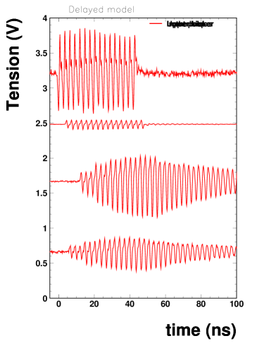
3.1.2 Delayed feedback
The delay loop to be added to the “delayed feedback” circuit could be made of a simple cable, but as there are losses, an amplifier must be included in the design to ensure that the delay loop has a gain of 1. The noise figure of this amplifier must be low to avoid accumulating and amplifying noise in the loop. The circuit layout is shown on figure 14.

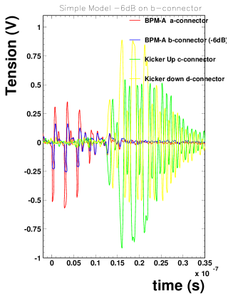
The figure 15 shows the input and output that were measured with this layout, using a delay loop with a length equivalent to 3 pulses. It can clearly be seen that the information is “accumulated” in the delay loop while bunches arrives with offset (which means that the correction is not yet enough) and then that once full correction is reached (no more signal on the input) almost the same level of correction is kept (the decay comes from the fact that the gain of the delay loop was not matched to one).
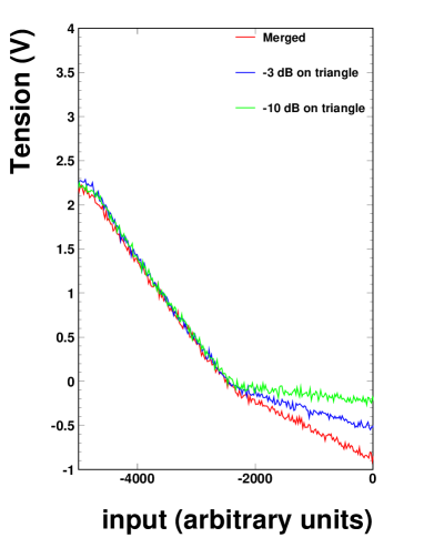
3.1.3 Improved feedback: Non linearity at RF frequencies.
A key issue to check the feasibility of the improved model of feedback is the possibility of generating a non linear response out of the components available at the working frequency.
This non-linearity can be simulated by using a diode. The blocking tension of this diode can by shifted by adding a DC (or low frequency) component to the incoming signal and subtracting this DC components after the diode, as shown on figure 16. Using this design, a kink of various angle has been observed when a normal triangle signal was sent through the circuit (see figure 17 ).

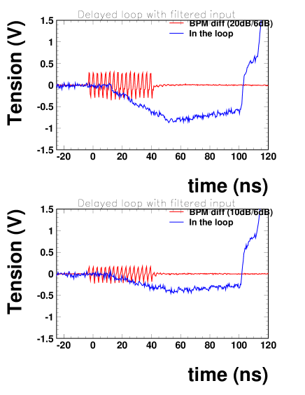
3.2 Kicker requirements and signal filtering
With the kickers currently available at KEK the tension required to kick the beam is of the order of the kilovolt. The only available amplifiers able to deliver this power does not work in the hundreds of megahertz range and thus the signal must be brought to a lower frequency.
This can be done by using a specific filter that reduces the frequency of the signal. It has been checked that the delayed model design remains valid with such filter (see figure 18).
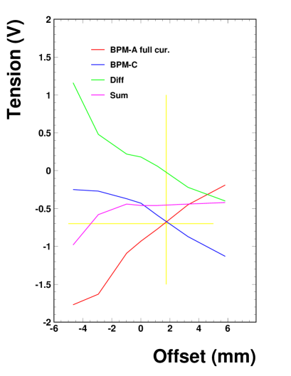
3.3 Online measurements
The response of a BPM as a function of the Beam Position has been measured at the ATF (here a “button” type BPM was used) as shown on figure 19.
Other beam tests have been done to measure how the trajectory is modified by a given kick. Initial results were not conclusive due to insufficient power but the effect of the kick was later observed with a more powerful pulse generator (see figure 20). To be able to check the full feedback system a new kicker requiring less power needs to be designed.
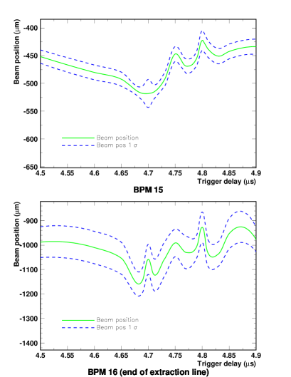
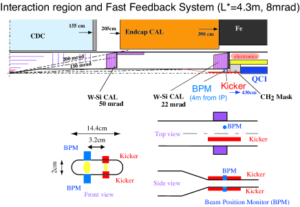
4 In the detector
The location of the feedback system will greatly influence its efficiency. The closest from the IP, the better performances can be reached. On an other hand, a system close from the IP will suffer from high radiation rate and absorb valuable particles, affecting the detector’s resolution. The best location seems to be 4 meters away from the IP as shown on figure 21.
5 Conclusion
The feasibility of a fast feedback system has been checked by the FEATHER collaboration. A new kicker is currently been designed. Once this new kicker will be ready new beam tests will be performed to confirm the results obtained on a test bench.