Now at: ]Los Alamos National Laboratory, Los Alamos, NM 87545
Experimental Identification of the Kink Instability as a Poloidal Flux Amplification Mechanism for Coaxial Gun Spheromak Formation
Abstract
The magnetohydrodynamic kink instability is observed and identified experimentally as a poloidal flux amplification mechanism for coaxial gun spheromak formation. Plasmas in this experiment fall into three distinct regimes which depend on the peak gun current to magnetic flux ratio, with (I) low values resulting in a straight plasma column with helical magnetic field, (II) intermediate values leading to kinking of the column axis, and (III) high values leading immediately to a detached plasma. Onset of column kinking agrees quantitatively with the Kruskal-Shafranov limit, and the kink acts as a dynamo which converts toroidal to poloidal flux. Regime II clearly leads to both poloidal flux amplification and the development of a spheromak configuration.
pacs:
52.55.Ip,52.35.Py,52.30.CvThe spheromak Jarboe94 ; Bellan00 is a simply-connected plasma configuration in which the magnetic fields are largely determined by dynamo-driven plasma currents. Because of its topological simplicity and ease of formation, the spheromak is of interest as a magnetic fusion confinement scheme Mclean02 . Spheromak formation has traditionally been explained by Taylor’s hypothesis Taylor86 that a turbulent magnetohydrodynamic (MHD) system relaxes to a state of minimum magnetic energy subject to the constraint of constant magnetic helicity. While this hypothesis has successfully explained the existence and many equilibrium properties of spheromaks, it says nothing about the actual 3D dynamics underlying the relaxation process, e.g., for coaxial gun spheromaks, the dynamo mechanism which converts injected toroidal flux into required poloidal flux al-Karkhy93 . The dynamics must be 3D because Cowling’s theorem Cowling34 shows that purely axisymmetric processes cannot accomplish this. This Letter experimentally identifies the MHD kink instability Freidberg87 as a 3D mechanism which converts toroidal to poloidal flux in a coaxial gun system, thereby leading to spheromak formation. This mechanism should also be of fundamental importance to coaxial helicity injection in spherical tori Raman03 , relaxation in reversed-field pinches Taylor86 , solar coronal plasma instabilities Vrsnak91 , and astrophysical jets Li01 .
Plasmas in this experiment fall into three regimes depending on peak (where is the gun current and is the bias poloidal magnetic flux intercepting the inner gun electrode), with (I) low values resulting in a straight plasma column with helical magnetic field along the symmetry axis, (II) intermediate values leading to kinking of the column axis, and (III) high values leading immediately to a detached plasma with . Onset of column kinking agrees quantitatively with the Kruskal-Shafranov limit Freidberg87 , and the kink acts as a dynamo which converts toroidal to poloidal flux. Regime II clearly leads to both poloidal flux amplification and magnetic field profiles consistent with spheromak formation. These results are qualitatively consistent with recent time-dependent resistive MHD numerical simulations of electrostatically driven spheromaks Sovinec01 .
Early coaxial gun experiments Lindberg64 demonstrated poloidal flux amplification, and it was postulated that this was due to an observed helical instability. More recently, toroidal mode number central column instabilities in coaxial gun experiments were reported by several spheromak research groups Knox86 ; Browning92 ; Nagata93 ; Duck97 ; Brennan99 . Typically, the observations were based on edge magnetic measurements, and the mode was studied in the context of relaxation during sustainment. Two hypotheses were proposed to explain the mode: (1) development of a surface in the closed-flux region Knox86 ; Nagata93 or equivalently a magnetic axis kink, and (2) current-driven instability of the central column Duck97 ; Brennan99 or equivalently a geometric axis kink. Additionally, the mode was shown to couple power from the central column to the spheromak Browning92 . The present work offers a significant new result in that a nonlinear geometric axis kink is directly observed to produce the dynamo and poloidal flux amplification leading to spheromak formation.
Building on a prior Caltech spheromak formation experiment Yee00 , the present experiment simplifies, and makes more accessible, the spheromak formation process by using a novel coaxial gun Hsu02a . A schematic of the gun is shown in Fig. 1, along with the cylindrical coordinate system. The gun consists of two concentric, co-planar copper electrodes: a 20 cm diameter disk (blue) biased to negative polarity high voltage surrounded by a 50 cm outer diameter annulus (green) connected to vacuum chamber ground. The width of the gap between electrodes is 6 mm. The inner electrode is mounted on the end of a vacuum re-entrant port; both are electrically insulated from the vacuum chamber by a ceramic break. The co-planar arrangement of the electrode surfaces is geometrically simple, allows the spheromak formation process to be diagnosed with no mechanical obstructions, and is feasible to model numerically Tokman02 . Bias field poloidal flux -contours are also shown in Fig. 1; can be adjusted from 0–7 mWb. Both and bias field point toward the inner electrode. The rise time of is 10 ms, making it essentially stationary on the much faster time scale of the gun discharge (tens of s). The gun is installed at one end of a much larger vacuum chamber (about 2 m long and 1.5 m diameter), and thus boundary effects on the spheromak formation process are minimized. The gun is powered by an ignitron-switched 120 F, 20 kV capacitor bank. Hydrogen gas is injected transiently using fast puff valves at eight equally spaced toroidal positions on each electrode. Due to the Paschen effect, the optimum path for plasma breakdown is along the bias field and not at the gap between electrodes. The capacitor bank is discharged at , at which time the bias field and gas puff have already been introduced, and breakdown occurs at approximately 4 s.
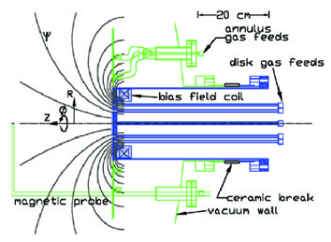
The main diagnostics are a multiple-frame fast CCD camera and a 60-channel magnetic probe array. The camera takes a sequence of time-resolved images in one plasma shot. The capability to visually follow the global evolution of a plasma in one plasma shot is a new and unique aspect of this work. The inter-frame time is typically 1 or 1.5 s, and the exposure time of each frame is 10 or 20 ns. False color is applied to the images for viewing. The magnetic probe array, shown in Fig. 1, measures all three components (, , ) of at 20 radial positions with 2 cm radial spacing. Probe signals are acquired using a digital acquisition system and integrated numerically on a computer. For all measurements in this paper, the probe is located at cm from the plane of the gun electrodes. Kink occurrence is independent of the probe (see Figs. 2 and 3). Propagation of the plasma in past the stationary probe relates temporal information to -spatial information. This relationship improves as the propagation past the probe becomes fast compared to the plasma expansion rate; this was exploited in the prior Caltech spheromak experiment Yee00 . The time dependence thus acts as a proxy for the -dependence. is measured with a Rogowski coil surrounding the ceramic break, and gun voltage is measured using a high-voltage probe. Typical parameters are: –6 kV (charge voltage) and 2–2.5 kV (after breakdown), peak –120 kA, –2 mWb, –1 kG, cm-3, and eV.
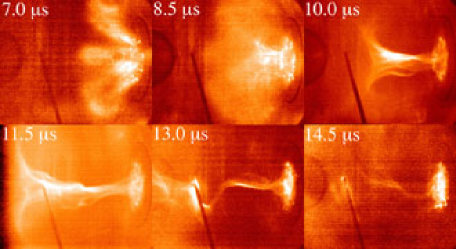
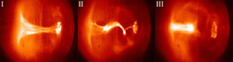
Figure 2 shows the time evolution of a kinked plasma (shot 2472). Gun electrodes are on the right side of each frame, and the -axis is oriented horizontally across the middle of each frame. At 7 s, bright arches are visible soon after breakdown, showing that breakdown occurs along the vacuum bias field lines. As increases, the arches expand and quickly merge together (8.5 s), forming a plasma column (10 s) which begins to kink (11.5 s) and then becomes strongly kinked (13 s). It will be shown that this sequence leads to a spheromak. Depending on peak , three distinct plasmas result, as shown in Fig. 3. Regime I leads to a stable column, II to a kinked column and then a spheromak, and III to an immediately detached plasma. The transition from regime I to II (II to III) occurs for peak (60) m-1.
In order to show that the helical perturbation is an MHD kink mode, consider the time evolution of the profile (relative to geometric axis), which is shown in Fig. 4 (shot 2472). The kink mode becomes linearly unstable when , where is the column length; this is the Kruskal-Shafranov limit. Since the kink involves a shift of the current channel, this requires on axis and in its vicinity. As seen in Fig. 4, near the axis is greater than unity at 9.5 s but flattens and approaches unity by 11.5 s, coinciding with onset of column kinking (Fig. 2). The kink is fully developed at 13 s and has broken apart by 14.5 s. The profile is determined using local and data from the magnetic probe array, and is determined from the CCD images. In addition, for an ensemble of plasma shots in which a column forms (regimes I and II), the Kruskal-Shafranov limit (recast Hsu02b as ) is a good predictor Hsu02b of whether a kink actually develops (Fig. 5). Thus, two sets of independent data (magnetic probe measurements of and , and Rogowski/flux loop measurements of ) both give direct evidence that the helical perturbation is an MHD kink mode. It is interesting to note that the observed kinks always have one axial wavelength, even though there is no fixed boundary at the end of the plasma column. One explanation Nakamura01 for this is that there is a strong axial gradient in , and thus an effective Alfvén speed discontinuity, which acts as a rigid boundary. This conjecture is consistent with the “mushroom cap” on the left side of the kink in Fig. 3.


Next, it is shown that the kink is followed immediately by three signatures of spheromak formation: (1) appearance of closed -contours [calculated assuming axisymmetry, ], (2) -amplification, and (3) magnetic field radial profiles consistent with spheromak formation. It is important to note that the relationship between closed -contours and closed flux surfaces becomes ambiguous when axisymmetry is broken. Thus, in the presence of a non-axisymmetric rotating kink, closed -contours indicate closed flux surfaces only in a time-averaged way. Shortly after 13 s, the kink breaks apart (Fig. 2). This coincides with signatures of spheromak formation as observed in the magnetic probe measurements (Fig. 6). At approximately 13 s, closed -contours appear and is amplified to larger than (-amplification is due mainly to broadening of the profile after 12 s). At 15 s, magnetic field profiles consistent with spheromak formation are observed (Fig. 7). The measured radial profiles of and at 15 s are compared with Taylor state solutions Taylor86 in cylindrical geometry, i.e. uniform solutions of
| (1) |
The solutions are and , where and are Bessel functions of order zero and one, respectively, and the best fit is found for m-1 with a radial offset of 4 cm (displacement of spheromak off the geometric axis). The slight disagreement between measured profiles and the Taylor solution is not surprising since the spheromak is expected to be either (1) still undergoing relaxation toward the Taylor state or (2) in a modified relaxed state since it is still being driven by the gun which has peak m-1.


The kink modifies the direction of current-flow from (poloidal) to (toroidal), as seen in Fig. 2. Equivalently, it converts toroidal to poloidal flux. This process is paramagnetic, amplifying over the initial applied mWb. The paramagnetism is understood by realizing that kinks involve perturbations with dependence where . The latter means . Thus, a locus of constant phase of the kink is given by , meaning that the kinked current channel is a right (left) handed helix if (). This will always lead to amplification of the original . The additional introduced by the kink can be estimated by approximating the helix as a solenoid with current , turns per length , and radius . The solenoid formula for the field inside the solenoid is ; the produced by the solenoid is and thus depends non-linearly on the kink amplitude . Using the measured values cm, cm, and kA at 13.5 s, the generated by the kink is predicted to be approximately 1 mWb, which is within a factor of 2 of the observed amplification of over . The discrepancy is within the accuracy of and measurements and of the calculation assuming axisymmetry in the presence of the rotating kink. Because the coaxial gun can only inject toroidal flux, 3D plasma dynamics must be responsible for exceeding . The dynamics are provided by the kink, which amplifies by converting toroidal to poloidal flux; thus, in this case, the kink constitutes the dynamo intrinsic to spheromak formation.
Regime II clearly leads to all three signatures of spheromak formation: closed -contours, -amplification, and proper magnetic field profiles. Regime I lacks both closed -contours and -amplification. Regime III may have closed -contours; however, associated with high , which could indicate that the plasma is still relaxing. This work indicates a close relationship between the kink threshold () and the spheromak formation threshold, which according to a static force-free treatment is also proportional to an inverse length. For example, solutions of Eq. (1) for uniform indicate that closed -contour equilibria exist for threshold , where () is the radius (length) of the flux conserver and is the first root of Bellan00 . Geometric differences among different experiments could result in different eigenmode spectra of Eq. (1) relative to the kink stability thresholds.
In summary, the MHD kink instability has been identified experimentally as a poloidal flux amplification mechanism for coaxial gun spheromak formation. An central column helical instability was observed during formation using multiple-frame CCD imaging. Onset of the perturbation was shown using two independent sets of data to agree quantitatively with the Kruskal-Shafranov limit. The kink acts as a dynamo which converts toroidal to poloidal flux, and it is followed immediately by three key signatures of spheromak formation: (1) closed -contours, (2) -amplification, and (3) magnetic field profiles similar to the Taylor state.
The authors acknowledge S. Pracko, C. Romero-Talamás, and D. Felt for technical assistance and H. Bindslev for asking about kink paramagnetism. Supported by a US-DoE Fusion Energy Postdoctoral Fellowship and US-DoE Grant DE-FG03-98ER544561.
References
- (1) T. R. Jarboe, Plasma Phys. Control. Fus. 36, 945 (1994).
- (2) P. M. Bellan, Spheromaks (Imperial College Press, London, 2000).
- (3) H. S. McLean et al., Phys. Rev. Lett. 88, 125004 (2002).
- (4) J. B. Taylor, Rev. Mod. Phys. 58, 741 (1986).
- (5) A. al-Karkhy et al., Phys. Rev. Lett. 70, 1814 (1993).
- (6) T. G. Cowling, Mon. Not. R. Astron. Soc. 94, 39 (1934).
- (7) J. P. Freidberg, Ideal Magnetohydrodynamics (Plenum Press, New York, 1987).
- (8) R. Raman et al., Phys. Rev. Lett. 90, 075005 (2003).
- (9) B. Vrs̆nak, V. Ruz̆djak, and B. Rompolt, Solar Physics 136, 151 (1991).
- (10) H. Li et al., Astrophys. J. 561, 915 (2001).
- (11) C. R. Sovinec, J. M. Finn, and D. del-Castillo-Negrete, Phys. Plasmas 8, 475 (2001).
- (12) L. Lindberg and C. T. Jacobsen, Phys. Fluids 7, S44 (1964).
- (13) S. O. Knox et al., Phys. Rev. Lett. 56, 842 (1986).
- (14) P. K. Browning et al., Phys. Rev. Lett. 68, 1718 (1992).
- (15) M. Nagata et al., Phys. Rev. Lett. 71, 4342 (1993).
- (16) R. C. Duck et al., Plasma Phys. Control. Fus. 39, 715 (1997).
- (17) D. Brennan et al., Phys. Plasmas 6, 4248 (1999).
- (18) J. Yee and P. M. Bellan, Phys. Plasmas 7, 3625 (2000).
- (19) S. C. Hsu and P. M. Bellan, IEEE Trans. Plasma Sci. 30, 10 (2002).
- (20) M. Tokman, S. C. Hsu, and P. M. Bellan, Bull. Amer. Phys. Soc. 47, 42 (2002).
- (21) S. C. Hsu and P. M. Bellan, Mon. Not. R. Astron. Soc. 334, 257 (2002).
- (22) M. Nakamura, Y. Uchida, and S. Hirose, New Astron. 6, 61 (2001).