Also at ]Moscow Institute of Physics and Technology, Dolgoprudny, Moscow region 141700, Russia
Also at ]General Physics Institute of RAS, Moscow 119991, Russia
Generation of High Quality Laser Accelerated Ion Beams
Abstract
In order to achieve a high quality, i. e. monoergetic, intense ion beam, we propose the use of a double layer target. The first layer, at the target front, consists of high-Z atoms, while the second (rear) layer is a thin coating of low-Z atoms. The high quality proton beams from the double layer target, irradiated by an ultra-intense laser pulse, are demonstrated with three dimensional Particle-in-Cell simulations.
pacs:
52.50.Jm, 52.59.-f, 52.65.Rr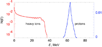
The high efficiency of ion acceleration recently observed in the interaction of petawatt laser pulses Mourou98 with solid targets ions1 has lead to important applications such as the use of laser produced fast ion beam injection to conventional accelerators (see Ref. injector-00 ), the fast ignition of thermonuclear targets, as discussed in Refs. Roth01 , and hadrontherapy in oncology BKh . Laser accelerated protons have been used for proton imaging of small scale objects in laser produced plasmas with high time resolution Borghesi . The process of ion acceleration has been studied in detail with multi-dimensional Particle-in-Cell (PIC) simulations Es99 . In the recent experimental results presented in Refs. ions1 , electron energy in a range of hundreds of MeV was observed, while the proton energy was about tens of MeV with a number of fast protons from to per pulse and with the transformation of of the laser energy into fast ion energy. In Refs. Es99 it was shown with PIC simulations that, by optimizing the laser-target parameters, it becomes possible to accelerate protons up to several hundreds MeV with a number of fast ions approximately particles per pulse.
The typical energy spectrum of laser accelerated particles observed both in the experiments and in the computer simulations can be approximated by a quasi-thermal distribution with a cut-off at a maximum energy . The effective temperature , that may be attributed to the fast ion beams, is much less than the maximal energy. On the other hand, almost all above mentioned applications require high quality proton beams, i.e., beams with sufficiently small energy spread . For example, for the hadron therapy it is highly desirable to have a proton beam with in order to provide the conditions for a high irradiation dose being delivered to the tumor saving neighboring healthy tissues KhM . In the concept of Fast Ignition with laser accelerated ions presented in Refs. Roth01 , the proton beam was assumed to be quasi-monoenergetic. An analysis carried out in Ref. Atzeni has shown that the Fast Ignition with a quasi-thermal beam of fast protons requires several times larger energy than that with a monoenergetic beam. Similarly, in the case of the injector (see Ref. injector-00 ), a high-quality beam is needed in order to inject the charged particles into the optimal accelerating phase efficiently. Thus we see that the generation of high quality beams is a key problem for many applications. However energy spectra of the laser accelerated ions at present are rather far from required ones.
In this Letter we show with three dimensional (3D) PIC simulations that such a required beam of laser accelerated ions can be obtained using a double layer target (see also Refs. BKh ). Multi layer targets have been used for a long time in order to increase the efficiency of the laser energy conversion into plasma and fast particle kinetic energy (see Refs. in Double ). In contrast to the configurations discussed previously, we propose to use a double layer target to produce fast proton beams with controlled quality.
In the proposed scheme the target is made of two layers. The first layer consists of high-Z atoms (atomic mass ), while the second layer is a very thin coating of low-Z atoms (atomic mass ). Such the target can be a metal foil coated with a thin hydrogeneous film. An ultra-intense laser pulse is incident on the first layer, and so we say that the first layer is at the target front, while the second layer is at the rear side of the target. We use the term ‘longitudinal’ for the direction of propagation of the laser pulse, and the term ‘transverse’ for perpendicular directions.
When an ultra-intense laser pulse irradiates the target, heavy atoms are partly ionized and electrons are expelled from the foil. A quasi-static electric field is generated due to charge separation. The first layer of heavy ions (the foil) should be sufficiently thick so as to produce a large enough quasi-static electric field, and, at the same time, it should be sufficiently thin to be able to produce strong electric field at the rear side. Such an electric field has opposite signs on the two sides of the target, and vanishes inside the target and at some finite distance from it. The number of low-Z ions in the second layer (the coating) should be sufficiently small not to produce any significant effect on the electric field. The quasi-static electric field accelerates both high-Z ions (with average charge ) and low-Z ions (with average charge ). If the ratio is sufficiently large, light ions are accelerated much more efficiently than heavy ones. The coated thin layer can be then accelerated forward. It detaches from the foil, and moves as a whole in the longitudinal direction. The light ions within a small solid angle have a quasi-monoenergetic energy spectrum. The thinner the coating the narrower energy spectrum of light ions is.
The important requirement is that the transverse size of the coating must be smaller than the laser waist since an inhomogeneity in the laser pulse causes nonuniform accelerating electric field and thus a degradation of beam quality, as seen in experiments presented in Refs. ions1 where the exposed targets had a thin proton layer on their surface. The laser pulse inhomogeneity results in an additional energy spread of the ion beam as seen in the experiments. The effect of the finite waist of the laser pulse leads also to an undesirable defocusing of the fast ion beam. In order to compensate for this effect and to focus the ion beam, we can use properly deformed targets, as suggested in Refs. Es99 ; W .
In a target, whose transverse size is much greater than the laser focal spot, quasi-static electric field can be affected by background ‘cold’ electrons from the periphery. To increase the quality and life-time of the quasi-static electric field, we should use targets with transverse size less than the laser waist.
In order to estimate the typical energy gain of fast ions, we assume that the main portion of the free electrons produced by ionization in the irradiated region of the foil are expelled. In this case the generated electric field near the positively charged layer is equal to . Here is the ion density and is an average ion electric charge in the foil, and is the foil thickness. The region of strong electric field has a transverse size of the order of the diameter of the focal spot. Thus the longitudinal size of the region where the electric field remains essentially one-dimensional is of the order of and the typical energy of an ion with charge accelerated by this electric field can be estimated as . We have assumed that the electron energy in the laser field is well above the ion energy and larger than the energy required for the electrons to leave the irradiated region. The maximum electron energy in the electromagnetic wave is given by , where is the dimensionless amplitude of the laser pulse. From this condition we can find the required value of the laser pulse intensity and its power.
Consider a double layer target in the form of a prolate ellipsoid coated at the rear side with a very thin proton layer. We assume that ellipsoid semiaxes are and . We can estimate the energy spectrum of protons, using formulae for the electric field of the electrically charged prolate ellipsoid LLEDCM . Let the -axis be in the longitudinal direction, originating from the target center. On this axis the -component of the electric field is given by . The distribution function of the fast protons obeys the kinetic equation . If particles trajectories do not intersect or self-intersect (for our ellipsoidal target this it true), we have , where is the distribution function at the initial time . The number of particles per unit volume in phase space, , is equal to We assume that at all particles are at rest and that their spatial distribution is given by which corresponds to the distribution function , with the Dirac delta function. For the applications discussed in this paper we are interested in the particle distribution function integrated over time. Time integration of the distribution gives the energy spectrum of the beam Here the Lagrange coordinate of the particle and the Jacobian are functions of the particle energy . The Lagrange coordinate dependence on the energy is given implicitly by the integral of the particle motion: , where is the electrostatic potential. In the case under consideration, we have and . The Jacobian is equal to the inverse of the particle acceleration at , i.e. . On the other hand the function is equal to . Hence, we obtain the expression for the energy spectrum in the form
| (1) |
We notice that the expression for the energy spectrum follows from the general condition of particle flux continuity in the phase space.
As we can see, in the vicinity of the target the electric field on the axis is homogeneous and equals to . Therefore, the form of the energy spectrum (1) is determined from the distribution of the proton density . We see that in general a highly monoenergetic proton beam can be obtained when the function is a strongly localized function, i.e. when the thickness of the proton layer is sufficiently small, and then .
The longitudinal emittance of the beam is defined as the product of the energy spread and the time length of the beam: . Using the expressions obtained above we find the longitudinal emittance of the accelerated proton beam . For MeV, m and we obtain MeV ps which is about 150 times smaller than the emittance observed in the experiments with non-optimized targets in Ref. Roth02 .
Near the axis, the radial component of the electric field depends linearly on the radius : . We find that the particle trajectory is described by where is the initial radial coordinate of the particle and . From this expression, for we find the transverse emittance of the fast proton beam: Here is the transverse size of the proton layer and is the beam divergence angle. For m, m and m the transverse emittance is of the order of 2.5 mm mrad.
For the hadron therapy the particle flux must be approximately to protons per second KhM . If the laser pulse is focused onto a spot with diameter m, CH layer with average density 1g/cm3 and thickness m provides fast protons per pulse.
In order to take into account the numerous nonlinear and kinetic effects as well as to extend our consideration to a multidimensional geometry, we performed numerical simulations of the proton acceleration during the interaction of a short, high power laser pulse with a two-layer target. We used the three dimensional massively parallel and fully vectorized code REMP (Relativistic Electro-Magnetic Particle-mesh code) REMP . In these simulations the largest number of grid cells was and the number of quasiparticles was up to . The boundary conditions for the particles and for the fields are periodic in the transverse directions and correspond to absorption at the ends of the computation box along the axis. The simulations were performed on 64 processors of the vector supercomputer NEC SX-5 at CMC, Osaka University.
Here we present the results of these simulations. The size of the simulation box is . A linearly polarized laser pulse with dimensionless amplitude propagates along the -axis. The pulse size is . The pulse has a trapezoidal shape (growth-plateau-decrease), with in the -direction, and in the - and -directions. The plasma consists of three species: electrons, protons with , and heavy ions (gold with ) with .
The first layer (gold) is placed at . It has the form of a disk with diameter and thickness . The second layer (protons) also has the form of a disk with diameter and thickness , and is placed at the rear of the first layer, at . The electron density in the heavy ion layer corresponds to the ratio between the plasma and the laser frequencies, for the proton layer it corresponds to . The number of electrons in the first layer is approximately times larger than that in the proton layer.
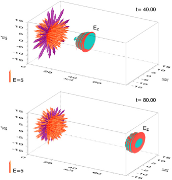
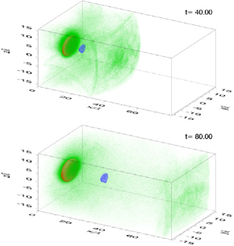
The simulation results are shown in Figs. 1 to 3, where the coordinates are measured in wave lengths of the laser light and the time in laser periods. In Fig. 1 we present the electric field inside the computation box, to show the shape of the transmitted laser pulse and the longitudinal electric field accelerating the protons. The electric field is shown as a three-dimensional vector field; it is localized in the vicinity of the first layer (the layer of heavy ions) of the target and can be described as an electrostatic field from a positively charged disk. The transmitted laser pulse is presented by the isosurfaces of constant value of the -component of the electric field. In Fig. 2 we show the densities of plasma species inside the computation box. We see that the proton layer moves along the -axis and that the distance between the two layers increases. The heavy ion layer expands due to Coulomb explosion and tends to become rounded. Part of the electrons is blown off by the laser pulse, while the rest forms a hot cloud around the target. We notice that for the simulation parameters the electrons do not expelled from the region irradiated by the laser light completely. Even if only a portion of the electrons is accelerated and heated by the laser pulse, the induced quasi-static electric field appears to be strong enough to accelerate the protons up , as seen in Fig. 3 presenting the energy spectra of the protons and heavy ions. The energy per nucleon acquired by the heavy ions is approximately 380 times smaller than the proton energy. The heavy ions have a wide energy spectrum while the protons form a quasi-mono-energetic bunch with . We emphasize that the thinner the proton layer (or low-Z coating) the better the beam quality is. The proton beam remains localized in space for a long time due to the bunching effect of the linearly decreasing electric field in the acceleration direction.
In conclusion, the use of the multi-layer targets with different shapes and compositions opens up new opportunities for controlling and optimizing the parameters of the fast proton (ion) beam, such as the energy spectrum, the number of particles per bunch, the beam focusing and the size of the region where the beam deposits its energy.
References
- (1) G. A. Mourou, C. P. J. Barty, M. D. Perry, Physics Today 51, 22 (1998).
- (2) A. Maksimchuk, S. Gu, K. Flippo, D. Umstadter, et al., Phys. Rev. Lett. 84, 4108 (2000); E. L. Clark, K. Krushelnick, M. Zepf, et al., Phys. Rev. Lett. 85, 1654 (2000); S. P. Hatchett, C. G. Brown, T. E. Cowan, et al., Phys. Plasmas 7, 2076 (2000); R. Snavely, M.H. Key, S.P. Hatchett, et al., Phys. Rev. Lett., 85, 2945 (2000); A. J. Mackinnon, M. Borghesi, S. Hatchett, et al., Phys. Rev. Lett. 86, 1769 (2001).
- (3) K. Krushelnik, E.L. Clark, R. Allot, et al., IEEE Trans. Plasma Science 28, 1184 (2000).
- (4) M. Roth, T. E. Cowan, M. H. Key, et al., Phys. Rev. Lett. 86, 436 (2001); V. Yu. Bychenkov, V. Rozmus, A. Maksimchuk, D. Umstadter, Plasma Phys. Rep. 27, 1076 (2001).
- (5) S. V. Bulanov, V. S. Khoroshkov, Plasma Phys. Rep. 28, 453 (2002); S. V. Bulanov, T. Zh. Esirkepov, A. V. Kuznetsov, V. S. Khoroshkov, F. Pegoraro, Phys. Lett. A, in press (2002).
- (6) M. Borghesi et al, Plasma Phys. Control. Fusion 43, A267 (2001); M. Borghesi et al, Phys. Rev. Lett. 88, 135002-1 (2002); M. Borghesi et al, Phys. Plasmas 9, 2214 (2002).
- (7) T. Zh. Esirkepov, Y. Sentoku, K. Mima, et al., JETP Lett. 70, 82 (1999); S. V. Bulanov, N. M. Naumova, T. Zh. Esirkepov, et al., JETP Lett. 71, 407 (2000); Y. Sentoku, T. V. Lisseikina, T. Zh. Esirkepov, et al., Phys. Rev. E 62, 7271 (2000); H. Ruhl, S. V. Bulanov, T. E. Cowan, et al., Plasma Phys. Rep. 27, 411 (2001); A. M. Pukhov, Phys. Rev. Lett. 86, 3562 (2001); Y. Sentoku, V. Yu. Bychenkov, K. Flippo, et al., Appl. Phys. B 74, 207215 (2002); A. J. Mackinnon, Y. Sentoku, P. K. Patel, et al., Phys. Rev. Lett. 88, 215006-1 (2002).
- (8) V. S. Khoroshkov, E. I. Minakova, Eur. J. Phys. 19, 523 (1998); G. Kraft, Physica Medica - Vol. XVII, Supplement 1, p. 13 (2001); U. Amaldi, Physica Medica - Vol. XVII, Supplement 1, p. 33 (2001).
- (9) S. Atzeni, M. Temporal, J.J. Honrubia, Nucl. Fusion 42, L1 (2002).
- (10) J . Badziak, E. Woryna, P. Parys, et al., Phys. Rev. Lett. 86, 215001 (2001).
- (11) S. C. Wilks, A. B. Langdon, T. E. Cowan, et al., Phys. Plasmas 8, 542 (2001).
- (12) M. Roth, et al., in: Proceed. Second International Conference on Superstrong Fields in Plasmas, Villa Monastero, Varenna (Lc), Italy, August 27 - September 1, 2001// edited by M. Lontano et al. (American Institute of Physics 0-7354-0057-1/02), p. 199.
- (13) L. D. Landau and E. M. Lifshits, Electrodynamics of Continouos Media (Pergamon. Oxford, 1988).
- (14) T. Zh. Esirkepov, Comput. Phys. Comm. 135, 144 (2001).