Improved large-mode area endlessly single-mode photonic crystal fibers
Abstract
We numerically study the possibilities for improved large-mode area endlessly single mode photonic crystal fibers for use in high-power delivery applications. By carefully choosing the optimal hole diameter we find that a triangular core formed by three missing neighboring air holes considerably improves the mode area and loss properties compared to the case with a core formed by one missing air hole. In a realized fiber we demonstrate an enhancement of the mode area by without a corresponding increase in the attenuation.
pacs:
060.2280, 060.2300, 060.2310, 060.2400, 060.2430Applications requiring high-power delivery call for single-mode large-mode area (LMA) optical fibers. While standard-fiber technology has difficulties in meeting these requirements the new classknight1996 of all-silica photonic crystal fibers (PCF) has a big potential due to their endlessly single-mode properties birks1997 combined with (in principle) unlimited large effective areas.knight1998el For recent reviews we refer to Refs. birks2001, ; knight2002, .
The cladding structure of these PCFs consists of a triangular array of air holes of diameter and pitch corresponding to an air-filling fraction . The presence of the air holes results in a strongly wavelength dependent effective index of the cladding and in the short and long wavelength limits we have
| (1) |
The numerical results in the intermediate regime can be reasonably fitted by e.g.
| (2) |
with of order unity and only weakly dependent on , see Fig. 1. It is these unusual dispersion properties of the cladding which facilitate design of large-mode area endlessly single-mode optical fibers.birks1997 ; knight1998el
In order to confine the light to a core region of high index a defect in the triangular air-hole array is introduced. Normally this is done by leaving out one of the air holes. In the stack-and-pull approach knight1996 one of the capillaries is replaced by a silica rod, see left insert of Fig. 3. By choice the index of the defect can be raised by various doping and depressed-index core has also been studied recently.mangan2001
The single-rod PCF can in principle be kept endlessly single-mode no matter how large a core diameter.knight1998el However, when scaling-up the fibre-structure the mode area is increased at the cost of an increased susceptibility to longitudinal modulations mortensen_ptl such as e.g. micro-bending nielsen2002 and macro-bending sorensen2001 induced scattering loss. The reason is that in order to increase the mode area the pitch is scaled to a large value, but this also implies that and in this limit the core index approaches the cladding index, see Eq. (1). Fig. 1 suggests that the decreasing index step may be compensated by increasing the air hole diameter, which can be done up to which is the upper limit for endlessly single-mode operation. For a discussion of the particular mumber see e.g. Refs. broeng1999, ; mortensen2002a, ; kuhlmey2002, . For LMA PCFs working in the UV and visible regimes this sets an upper limit on the mode areas that can be realized with a reasonable loss and many applications call for an improved LMA PCF design.

The inclusion of more than a single solid rod in the stacking has been used to form multiple-core mangan2000 and highly birefringent PCFs.hansen2001 In this work we demonstrate how inclusion of more neighboring solid rods can be used for improved LMA endlessly single-mode PCFs. Intuitively this may not seem to be a promising direction since a reduced value of is needed to keep the PCF endlessly single-mode. For the birefringent case with two neighboring rodshansen2001 the limit is and for a triangular core formed by three neighboring rods (see right insert of Fig. 3) we have found as the upper limit for endlessly single-mode operation. However, for a given desired mode area this decrease in is compensated for by a corresponding smaller value of . In fact, the edge-to-edge separation of the holes turns out to be the important length scale rather than the pitch itself.
In introducing a multiple number of rods an important question about possible birefringence arises. The structure with a single rod has a six-fold symmetry and though group theory clearly excludes any intrinsic birefringence white2001 there has been quite some debate based on numerical studies, see e.g. Ref. koshiba2001, and references therein. More generally, group theory predicts that for -fold rotational symmetry and a mode with a preferred direction is one of a pair, see Ref. white2001, and references therein. PCFs with a triangular core formed by three neighboring rods have a -fold symmetry and thus no intrinsic birefringence. The non-birefringent property is also confirmed numerically using a fully-vectorial plane-wave method johnson2001 and any small numerical birefringence originates from a numerical grid with symmetry different from the dielectric structure being studied.
In order to compare the single-rod and three-rod PCFs we study two quantities; i) the mode-field diameter and ii) the coupling length to the cladding. We relate the to the effective areamortensen2002a
| (3) |
by . Here, is the transverse intensity distribution of the fundamental mode. For a Gaussian mode of width Eq. (3) gives and the intensity distribution in the types of PCF studied in this work can be considered close to Gaussianmortensen2002a ; mortensen2002b as we also confirm experimentally.
The coupling length (beat length)
| (4) |
between the fundamental mode and the cladding (radiation field) can be used in formulating a low-loss criterion.love The additional competing length scales consist of the wavelength and the length scale (or as set of length scales) for nonuniformity along the fiber and loss will be significant when
| (5) |
and otherwise loss can be expected to be small. Thus, the shorter a coupling length the lower susceptibility to longitudinal modulations. We emphasize that this criterion does not quantify loss, but it gives a correct parametric dependence of loss for various loss mechanisms. For PCFs the relevance of this criteria was recently confirmed experimentally in the case of macro-bending mortensen_ptl and micro-bending nielsen2002 induced nonuniformities and also in a study of PCFs with structural long-period gratings.kakarantzas2002
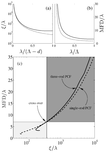
In Fig. 2 we compare the single-rod and three-rod PCFs with and , respectively. All numerical results are based on a fully-vectorial solution of Maxwell’s equations in a plane-wave basisjohnson2001 and for silica we have for simplicity used . Panel (a) shows the coupling length versus wavelength. The normalization by the edge-to-edge separation of the air holes makes the two curves coincide at short wavelengths () which clearly demonstrates that is the length scale of the fiber structure which determines the susceptibility to longitudinal modulations. Panel (b) shows the mode-field diameter as a function of wavelength and as seen the three-rod PCF provides a larger compared to the single-rod PCF for fixed . Panel (c) combines the results of panels (a) and (b) in a plot of mode-field diameter versus coupling length. At there is a clear cross over and for the three-rod PCF is thus seen to be less susceptible to longitudinal modulations compared to the single-rod PCF.
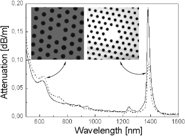
Fig. 3 shows experimental results for the attenuation of both a single-rod PCF and a three-rod PCF with hole diameters ( and , respectively) close to the endlessly single-mode limits. The pitches are and , respectively, so that core sizes are approximately the same. The two PCFs were fabricated by aid of the stack-and-pull method under comparable conditions and both PCFs were found to be endlessly single-mode in a wavelength range of at least to . As seen the two PCFs have similar spectral attenuation even though the mode area of the three-rod PCF is enhanced by compared to the single-rod PCF. This demonstrate the improvement by the three-rod PCF.
In conclusion we have found that a triangular core formed by three missing neighboring air holes considerably improves the mode area and/or loss properties compared to the case with a core formed by one missing air hole. This new improved large-mode area endlessly single-mode PCF is important for high-power delivery applications and in a realized fiber we have been able to demonstrate an enhancement of the mode area by without a corresponding change in the loss level.
We acknowledge A. Bjarklev (Research Center COM, Technical University of Denmark) and J. Broeng (Crystal Fibre A/S) for useful discussions. M. D. N. is financially supported by the Danish Academy of Technical Sciences.
References
- (1) J. C. Knight, T. A. Birks, P. S. J. Russell, and D. M. Atkin, Opt. Lett. 21, 1547 (1996).
- (2) T. A. Birks, J. C. Knight, and P. S. J. Russell, Opt. Lett. 22, 961 (1997).
- (3) J. C. Knight, T. A. Birks, R. F. Cregan, P. S. J. Russell, and J.-P. De Sandro, Electron. Lett. 34, 1347 (1998).
- (4) J. C. Knight and P. S. J. Russell, Science 296, 276 (2002).
- (5) T. A. Birks, J. C. Knight, B. J. Mangan, and P. S. J. Russell, IEICE Trans. Electron. E84-C, 585 (2001).
- (6) B. J. Mangan, J. Arriaga, T. A. Birks, J. C. Knight, and P. S. J. Russell, Opt. Lett. 26, 1469 (2001).
- (7) N. A. Mortensen and J. R. Folkenberg, preprint.
- (8) M. D. Nielsen, G. Vienne, J. R. Folkenberg, and A. Bjarklev, Opt. Lett. in press (2002).
- (9) T. Sørensen, J. Broeng, A. Bjarklev, E. Knudsen, and S. E. B. Libori, Electron. Lett. 37, 287 (2001).
- (10) J. Broeng, D. Mogilevstev, S. E. Barkou, and A. Bjarklev, Opt. Fiber Technol. 5, 305 (1999).
- (11) N. A. Mortensen, Opt. Express 10, 341 (2002).
- (12) B. T. Kuhlmey, R. C. McPhedran, and C. M. de Sterke, Opt. Lett. 27, 1684 (2002).
- (13) B. J. Mangan, J. C. Knight, T. A. Birks, and P. S. J. Russell, Electron. Lett. 36, 1358 (2000).
- (14) T. P. Hansen, J. Broeng, S. E. B. Libori, E. Knudsen, A. Bjarklev, J. R. Jensen, and H. Simonsen, IEEE Photon. Tech. Lett. 13, 588 (2001).
- (15) T. P. White, R. C. McPhedran, C. M. de Sterke, L. C. Botton, and M. J. Steel, Opt. Lett. 26, 1660 (2001).
- (16) M. Koshiba and K. Saitoh, IEEE Photon. Tech. Lett. 13, 1313 (2001).
- (17) S. G. Johnson and J. D. Joannopoulos, Opt. Express 8, 173 (2001).
- (18) N. A. Mortensen and J. R. Folkenberg, Opt. Express 10, 475 (2002).
- (19) J. D. Love, IEE Proc.-J 136, 225 (1989).
- (20) G. Kakarantzas, T. A. Birks, and P. S. J. Russell, Opt. Lett. 27, 1013 (2002).