Guided Modes in Negative Refractive Index Waveguides
Abstract
We study linear guided waves propagating in a slab waveguide made of a negative-refraction-index material, the so-called left-handed waveguide. We reveal that the guided waves in left-handed waveguides possess a number of peculiar properties, such as the absence of the fundamental modes, mode double degeneracy, and sign-varying energy flux. In particular, we predict the existence of novel types of guided waves with a dipole-vortex structure of the Pointing vector.
pacs:
41.20.Jb, 42.70.QsRecent experimental demonstration of novel composite materials with a negative index of refraction Shelby:2001-77:SCI opens up a unique opportunity to design novel types of devices where electromagnetic waves are governed in a non-conventional way. The history of these materials begins with the paper by Veselago Veselago:1967-517:UFN , who studied the wave propagation in a hypothetical material with simultaneously negative dielectric permittivity and magnetic permeability . Such media are usually termed left-handed materials, since the electric and magnetic fields form a left set of vectors with the wave vector. Already back in 1968, Veselago predicted a number of remarkable properties of waves in left-handed materials, such as negative refraction, reversed Doppler and Vavilov-Cherenkov effects. However, structures with both negative and have not been known until recently, although materials with negative dielectric permittivity are known (e.g. a metal below the plasma frequency).
The study of microstructured metallic materials for magnetic resonance imaging Wiltshire:2001-849:SCI has shown that such structures can be described in terms of effective magnetic permeability which becomes negative in the vicinity of a resonance frequency. It was expected that mixing the composite materials with negative magnetic permeability Wiltshire:2001-849:SCI with those possessing negative dielectric permittivity Pendry:1996-4773:PRL would allow to create a novel type of metamaterials with a negative index of refraction. Indeed, both numerical simulations Markos:2001-33401:PRB+ and experimental results Shelby:2001-77:SCI ; Smith:2000-4184:PRL confirmed that such left-handed (or negative-index refraction) materials can be fabricated and analyzed.
One of the first applications of the negative-refraction materials was suggested by Pendry Pendry:2000-3966:PRL , who demonstrated that a slab of a lossless negative-refraction material can provide a perfect image of a point source. Although the perfect image is a result of an ideal theoretical model used in Ref. Pendry:2000-3966:PRL , the resolution limit was shown to be independent on the wavelength of electromagnetic waves (but can be determined by other factors such as loss, spatial dispersion, etc.), and it can be better than the resolution of a conventional lens Luo:2002-201104:PRB .
The improved resolution of a slab of the negative-refraction material can be explained by the excitation of surface waves at both interfaces of the slab. Therefore, it is important to study the properties of surface waves at the interfaces between the negative-refraction and conventional materials. So far, the frequency dispersion of surface waves at a single interface and in a slab waveguide was calculated numerically only for particular medium parameters Ruppin:2000-61:PLA+ .
In this Letter, we study, for the first time to our knowledge, the structure and basic properties of electromagnetic waves guided by a left-handed waveguide. In order to emphasize the unusual and somewhat exotic properties of such waves, we compare them with the guided waves of conventional planar dielectric waveguides. We reveal that the guided modes in left-handed waveguides differ dramatically from conventional guided waves, and they possess a number of unusual properties, including the absence of the fundamental modes, double degeneracy of the modes, the sign-varying energy flux, etc. In particular, we predict the existence of novel types of guided waves with a dipole-vortex structure of the energy flux and the corresponding Pointing vector.
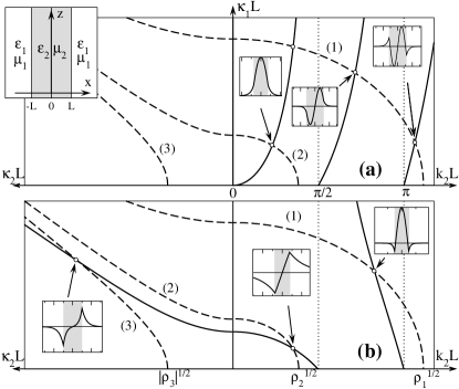
We consider a symmetric slab waveguide in a conventional planar geometry [see, e.g., the top left insert in Fig. 1(a)]. In the general case, a slab of the thickness is made of a material with dielectric permittivity and magnetic permeability , which both can be negative or positive. We assume that the surrounding medium is right-handed, and is therefore characterized by both positive and . It is well known that a slab waveguide made of a conventional (right-handed) dielectric material with and creates a non-leaky waveguide for electromagnetic waves, provided the refractive index of a slab is higher than that of the surrounding dielectric medium (cladding), i.e. . However, in the following we demonstrate that this simple criterion can not be applied to the waveguides made of a left-handed material.
To be specific, below we describe the properties of the TE guided modes in which the electric field is polarized along the axis. A similar analysis can be carried out for the TM modes, and these results will be presented elsewhere. From the Maxwell’s equations, it follows that stationary TE modes can be described by the following equation for the scalar electric field ,
| (1) |
where is the angular frequency of the monochromatic waves.
The guided modes can be found as special stationary solutions of Eq. (1) having the following form,
| (2) |
where real is the wave propagation constant and is the spatially localized transverse profile of the mode. After substituting Eq. (2) into Eq. (1), we obtain an eigenvalue problem that possesses spatially localized solutions for
| (3) |
because only in this case the mode amplitude decays away from the waveguide, .
We solve the eigenvalue problem in each of the homogeneous layers, and then employ the corresponding boundary conditions following from Eq. (1). As a result, we obtain the dispersion relations which define a set of allowed eigenvalues ,
| (4) |
where the signs and correspond to the symmetric and antisymmetric guided modes, respectively, and . When is real, the corresponding modes can be identified as “fast waves”, since their phase velocity is larger than the phase velocity in an homogeneous medium with and .
The parameter becomes purely imaginary for “slow waves”, when the propagation constant exceeds a critical value. Then, it is convenient to present Eq. (4) in an equivalent form using ,
| (5) |
Following a standard textbook analysis (see, e.g. Ref. Vinogradova:1990:TheoryWaves ), we consider the parameter plane , and also extend it by including the imaginary values of using the auxiliary parameter plane . In Figs. 1(a,b), we plot the dependencies described by the left-hand (dashed) and right-hand (solid) sides of Eqs. (4) and (5), using a relation between the parameters,
| (6) |
In Figs. 1(a,b), we draw three dashed lines corresponding to different slab waveguides, having the same ratio . The intersections of a dashed line with solid curves indicate the existence of various guided modes. We present results for a conventional (right-handed) waveguide in Fig. 1(a), in order to compare them directly with the corresponding dependencies for a left-handed slab waveguide in Fig. 1(b).
First of all, the analysis of Eqs. (4) and (5) confirms the well-known textbook results that a right-handed slab waveguide can only support “fast” guided modes, which exist when the waveguide core has a higher refractive index than its cladding, i.e. for . In this case, there always exists a fundamental guided mode, which profile does not contain zeros. The conventional waveguide can also support higher-order modes, their number is limited by the value . These various regimes are illustrated in Fig. 1(a) with different dashed lines.
However, we find that the properties of the left-handed slab waveguides are highly nontrivial. First, such waveguides can support “slow” modes, and they are either symmetric (node-less) or antisymmetric (one zero). Such solutions represent in-phase or out-of-phase bound states of surface modes, localized at the two interfaces between right and left media. In the conventional case of both positive and , such surface waves do not exist, however they appear when the magnetic permeability changes its sign (for the TE polarization). Thus, the guided modes can be supported by both low-index and high-index left-handed slab waveguides.
Second, the conventional hierarchy of “fast” modes is removed. Specifically, (i) the fundamental node-less mode does not exist at all, (ii) the first-order mode exists only in a particular range of the parameter values , and it always disappears in wide waveguides, when exceeds a critical value, and (iii) two modes having the same number of nodes can co-exist in the same waveguide. We illustrate some of these nontrivial features in Fig. 1(b).
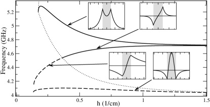
Frequency dispersion of the guided waves in the left-handed waveguides should be studied by taking into account the dispersion of both and , since this is an essential property of such materials Veselago:1967-517:UFN . We follow Ref. Smith:2000-4184:PRL and consider the following frequency dependencies of the effective left-handed medium characteristics,
| (7) |
where the parameters correspond to the experimental data of Ref. Smith:2000-4184:PRL : GHz, GHz, and . The region of simultaneously negative permittivity and permeability in this case ranges from 4 GHz to 6 GHz. Dispersion curves for the first three guided modes in a slab waveguide with the thickness parameter cm are shown in Fig. 2, where dashed curves correspond to “fast” modes, and solid – to “slow” modes. We find that the fundamental “slow” mode exists only at higher frequencies, whereas the second-order fast mode appears at lower frequencies. Both modes can have either positive or negative group-velocity dispersion in different parameter regions. Properties of the first-order antisymmetric mode are different. The type of this mode seamlessly changes from “fast” to “slow” as the frequency grows. This transition occurs when the condition is satisfied, which is a boundary separating the two types of modes, as shown in Fig. 2 by a dotted line. The high “fast” modes exists at the frequencies close to the resonance at .
In the left-handed materials, the electromagnetic waves are backward, since the energy flux and wave vector have opposite directions Veselago:1967-517:UFN , whereas these vectors are parallel in conventional (right-handed) homogeneous materials. The energy flux is characterized by the Pointing vector averaged over the period and defined as . A monochromatic guided mode has, by definition, a stationary transverse profile, and the averaged energy flux is directed along the waveguide only. It follows from the Maxwell’s equations and Eq. (2) that the -component of the energy flux is,
| (8) |
The total power flux through the waveguide core and cladding can be found as and , respectively. We find that the energy flux distribution for the waves guided along the left-handed slab is rather unusual. Indeed, the energy flux inside the slab (with ) is opposite to that in the surrounding medium (with ). This occurs because the normalized wave vector component along the waveguide () is fixed in a guided mode according to Eq. (2). An important information about the guided modes can be extracted from the study of the normalized energy flux . This parameter is bounded, , when the mode is weakly localized (), whereas for modes which are highly confined inside the left-handed slab.
We have performed a detailed analysis of the slow guided modes and identified four distinct cases.
(i) , . Only odd mode exists below the threshold, . The corresponding critical value of the slab thickness below which the odd mode exists is found as
| (9) |
The energy flux is positive for all values of . The modes are forward propagating, i.e. the total energy flux along the waveguide is co-directed with the wavevector.
(ii) , . Even mode exists at all values of , however odd modes can appear only when a threshold parameter value is exceeded, . Accordingly, the critical value (9) determines the lower boundary of the existence region for odd modes. The total energy flux is negative for all , and the modes are backward. The energy is mostly localized inside the slab.
(iii) , . Both odd and even modes exist at all values of and , and the modes are forward.
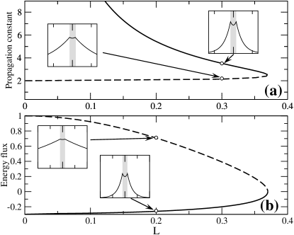
(iv) , . Only even modes exist below the threshold value of which can be found numerically using Eq. (5). Characteristic dependences of the wavenumber and normalized power on the slab width is shown in Figs. 3(a,b). At any slab thickness below a critical value, two modes always co-exist. One of the modes is forward and weakly localized, but the other one is backward and more confined. When the slab width approaches the critical value, the branches corresponding to different modes merge, and the energy flux vanishes. In this special case, the energy fluxes inside and outside the slab exactly compensate each other.
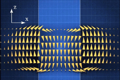
Since the energy fluxes are oppositely directed inside the guided modes, it might initially seem that such waves can only be sustained by two continuously operating emitters positioned at the opposite ends of the waveguide. Therefore, it is of the fundamental importance to understand whether wave packets of finite temporal and spatial extension can exist in left-handed waveguides. We calculate the Pointing vector averaged over the period of the carrier frequency, and present the characteristic structure of the energy flow in Fig. 4. Due to the unique double-vortex structure of the energy flow, most of the energy remains inside the wavepacket, and it does not disintegrate. The group velocity is proportional to the total energy flux , and it can therefore be made very small or even zero by a proper choice of the waveguide parameters as demonstrated above. On the other hand, the group-velocity dispersion, which determines the rate of pulse broadening, can also be controlled. This flexibility seems very promising for potential applications.
Finally, we note that recent numerical simulations demonstrated that the phenomenon of the negative refraction, similar to that found for the left-handed metamaterials, can be observed in photonic crystals Luo:2002-201104:PRB ; Kosaka:1998-10096:PRB+ . Although in this case the wavelength is of the same order as the period of the dielectric structure (and, therefore, a simple analysis in terms of the effective medium approximation is not strictly justified), we expect that similar mechanisms of wave localization will remain generally valid.
In conclusion, we have described, for the first time to our knowledge, linear guided waves in left-handed slab waveguides. We have demonstrated a number of exotic properties of such waves, including the absence of fundamental modes and the sign-varying energy flux, and we have predicted the existence of the fundamentally novel classes of guided waves with a vortex-type internal structure.
We thank C. T. Chan and C. M. Soukoulis for useful discussions, and to D. E. Edmundson for assistance with Fig. 4. The work was partially supported by the Australian Research Council.
References
- (1) R.A. Shelby, D.R. Smith, and S. Shultz, Science 292, 77 (2001).
- (2) V.G. Veselago, Usp. Fiz. Nauk 92, 517 (1967) [Sov. Phys. Usp. 10, 509 (1968)].
- (3) M.C.K. Wiltshire, J.B. Pendry, I.R. Young, D.J. Larkman, D.J. Gilderdale, and J.V. Hajnal, Science 291, 849 (2001).
- (4) J.B. Pendry, A.J. Holden, W.J. Stewart, and I. Youngs, Phys. Rev. Lett. 76, 4773 (1996).
- (5) P. Markoš and C.M. Soukoulis, Phys. Rev. B 65, 033401 (2001); D.R. Smith, S. Schultz, P. Markoš, and C.M. Soukoulis, Phys. Rev. B 65, 195104 (2002).
- (6) D.R. Smith, W. Padilla, D.C. Vier, S.C. Nemat-Nasser, and S. Shultz, Phys. Rev. Lett. 84, 4184 (2000).
- (7) J.B. Pendry, Phys. Rev. Lett. 85, 3966 (2000).
- (8) C. Luo, S.G. Johnson, J.D. Joannopoulos, and J.B. Pendry, Phys. Rev. B 65, 201104 (2002).
- (9) R. Ruppin, Phys. Lett. A 277, 61 (2000); J. Phys. Condens. Matter 13, 1811 (2001); F.D.M. Haldane, arXiv:cond-mat:0206420 (2002).
- (10) M. B. Vinogradova, O. V. Rudenko, and A. P. Sukhorukov, The Theory of Waves (Nauka, Moscow, 1990) (in Russian).
- (11) H. Kosaka, T. Kawashima, A. Tomita, M. Notomi, T. Tamamura, T. Sato, and S. Kawakami, Phys. Rev. B 58, 10096 (1998); M. Natomi, Opt. and Quant. Electron. 34, 133 (2002).