On unusual narrow transmission bands for a multi-layered periodic structure containing left-handed materials
Abstract
A multi-layered structure consisting of alternate right-handed material (RHM) and left-handed material (LHM)is considered and the unusual narrow transmission bands are explained as the competitive results of the Bragg condition and the transparent condition. These unusual narrow transmission bands may exist regardless whether the optical length of the LHM layer cancels the optical length of the RHM layer or not. This unusual transmission property may disappear when the reflection coefficient for each interface is small and the optical length of the LHM layer does not cancel the optical length of the RHM layer. An non-ideal model when the LHM is dispersive and lossy is also employed to confirm the unusual transmission phenomenon.
pacs:
78.20.Ci, 78.20.-e, 42.25.BsLeft-handed materials (LHMs) with negative permittivity and negative permeability, which were first suggested theoretically by Veselagoveselago , have attracted much attention recently after the experimental verifications smith ; shelby ; science ; pendry1 ; pendry2 .
One-dimensional (1D) structures consisting of alternate LHM and RHM layers have already been investigated through calculating the transmittance or the reflectance of the structures matrix ; bragg . The effects of photon tunnelling and reflective Bragg region were observed in these works. In the present paper we study the phenomenon of an unusual narrow transmission band at the middle of a reflective Bragg region. An non-ideal model when the material is dispersive and lossy is also employed to confirm the unusual phenomenon.
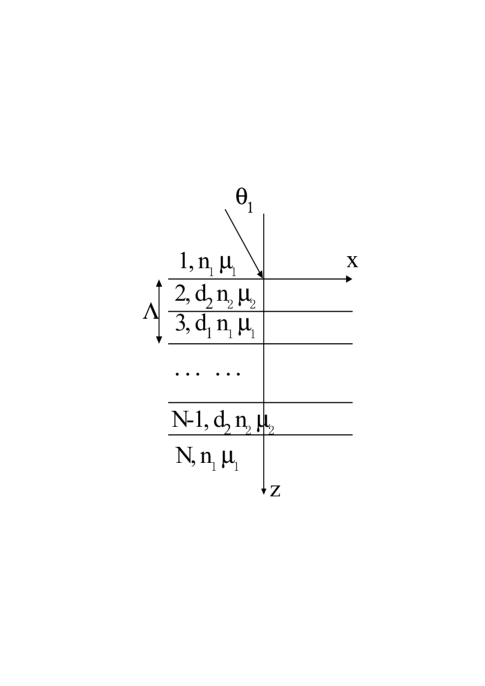
We consider a multi-layered periodic structure (with a finite thickness) consisting of alternate RHM and LHM layers (as shown in Fig. 1). For both polarizations, the electric field in the -th layer can be expressed as with , where and are the amplitudes of the forward and backward waves at the interface, respectively, and ( is the wavelength in vacuum) for a propagation wave with angle . The refraction index for the -th layer has the value for , and for . The LHM layers have the thickness and reflective index , while the internal RHM layers have the thickness and reflective index . The period is . Note that the same RHM material is used above and below the structure. The transform matrix method can be employed to calculate the transmittance and the reflectance matrix .
The amplitudes of the forward and backward waves for the first layer and the last layer are related by a matrix
| (5) |
Note that the matrix has different forms for the TE and TM waves matrix . The reflectance can be calculated by
| (6) |
A stack of alternate layers, which are known as a DBR (distributed Bragg reflector), exhibits very high reflectance in the well-known Bragg region. The Bragg region with a flat top and very steep edges (transitions) when the following Bragg condition is satisfied
| (7) |
where . There are two kinds of interfaces in the structure, namely, the interface and the interface. If one denotes the reflection coefficients for these two interfaces as and , then one has . When waves with the wavelength satisfying the above condition are reflected from the first-kind interfaces of different periods and reach the first interface, they add in phase (i.e., the phase differences are integer times of as compared with the wave reflected directly from the first interface), and consequently increase the reflectance (the reflectance will approach as the total number of the layers increases). If the value of varies a little bit , the phase differences change only a little bit (still almost integer times of ) for the waves reflected from the first a few periods, which reflect most of the incident waves (when the reflection coefficient for each interface is not too small). Therefore, one can still expect a large reflectance. This explains the flat-top region (centered at the Bragg wavelength) where the reflectance is almost . However, there are some cases when the above Bragg condition is satisfied but the Bragg region is not found. When that happens, a so-called transparent condition is also satisfied (and dominates).
The multi-layered structure is transparent at some discrete wavelength when the following transparent condition is satisfied
| (8) |
where . As mentioned above, on both sides of the stacked structure the medium has the refractive index . Note that the angle depends on . In such a case, the wave reflected from each second kind interface and the wave reflected from the first kind interface (just half-period before the corresponding second kind interface) are out of phase at the first interface (due to the property ) and thus the total reflection becomes zero. This gives a physical explanation for the transparent condition.
The above transparent condition can be proved mathematically in a straightforward way. Consider a 3-layered structure (i.e., ). The transform matrix is
where , for a TE wave, or for a TM wave. When condition (8) is satisfied, the above matrix is diagonal. Therefore, the slab is transparent to the waves with the wavelength satisfying the above condition for both TE and TM polarizations (cf. Eq. (2)). Since a wave which can go through a layer can also go through another layer, the whole multi-layered structure is transparent when the transparent condition is satisfied. Near the transparent wavelength, the transmission should still be allowed, however, with some oscillation (cf. the dotted line in Fig. 2(a) below).
From above discussion, one knows that the Bragg condition and the transparent condition are caused by the reflection at two different kinds of interfaces. In the present paper, we study the situation when both the Bragg condition and the transparent condition are satisfied at a certain wavelength since we wish to investigate some unusual narrow transmission bands (located at the middle of the flat-topped Bragg region mentioned in bragg ) of a periodic RHM-LHM structure. In such a situation, the reflection (or transmission) characteristics near this wavelength are the competitive result of the Bragg condition and the transparent condition (i.e., the competitive result of the reflection at the two kinds of interfaces). As we know, the reflective coefficients for the two kinds of interfaces are equal in absolute value. The phase difference of the two kinds of reflective waves are so important that it may decide the reflective characteristics of the whole structure.
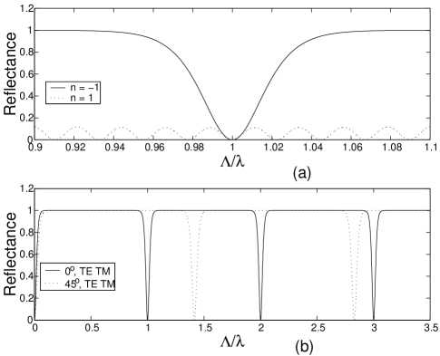
When both constitutive layers are of RHM (or LHM), the transmission will be quite large in a comparatively wide area centered at this wavelength (in other words, flat-topped Bragg region can not be formed) when both the Bragg condition and the transparent condition are satisfied (i.e., ; obviously, ). When ( is a small quantity), one has (i.e., the phase change for the transparent condition is smaller than that for the Bragg condition). Therefore, the transparent condition dominates and the transmission will be still quite large when the wavelength shifts away from this wavelength. This is illustrated by the dotted line in Fig. 2(a).
However, if the structure consists of alternate LHM and RHM layers, one can expect a quite different competitive result of the Bragg condition and the transparent condition. In this case, we can expect and thus (i.e., the phase change for the Bragg condition is smaller than that for the transparent condition) and the Bragg condition dominates (provided that and the reflection coefficient for each interface is not too small so that the contribution of the waves reflected from the first a few layers are important; see Fig. 3(b) and the related discussion below). The transparent wavelength shown in Eq. 8 can locate where the Bragg regime is formed. The solid line in Fig. 2(a) shows the reflectance for an example. For this example we have (i.e., the total optical length is ). In this special case, all wavelengths satisfy the Bragg condition and thus the Bragg condition always dominates except at some discrete points () where the transparent condition (8) is satisfied. Different from the previous case with (dotted line in Fig. 2(a)), when shifts from , the reflectance reaches steadily to form some very steep valleys. Fig. 2(b) shows the reflectance for the same structure with RHM-LHM period for both TE and TM incident waves when and over a wider wavelength region (here the horizontal axis is for , instead of , so that the reflection characteristics looks more periodic).
If (with ), we can still see the unusual narrow transmission bands due to the competitive result of the Bragg condition and the transparent condition. Fig. 3(a) shows such an example . In Fig. 3(a), and so that . At , where the Bragg condition and the transparent condition are both satisfied, makes the Bragg condition dominating when shifts from these wavelengths. Thus, steep valleys can be still observed in the reflectance spectrum. Comparing Fig. 2(b) (for the case of ) and Fig. 3, one sees that other transmission bands (with large and rapid oscillations- like conventional transmission bands for ordinary structure of RHM-RHM period) also exists when besides the unusual narrow transmission bands (with no sidelopes) . These oscillating transmission bands for a RHM-LHM periodic structure are located at where the transparent condition is satisfied while the Bragg condition is not satisfied. Note that the conventional (oscillating) transmission bands for a RHM-RHM periodic structure (cf. the dotted line in Fig. 2(a)) are located at some wavelengths where both the transparent condition and the Bragg condition are satisfied (however, the transparent condition dominates as discussed before).
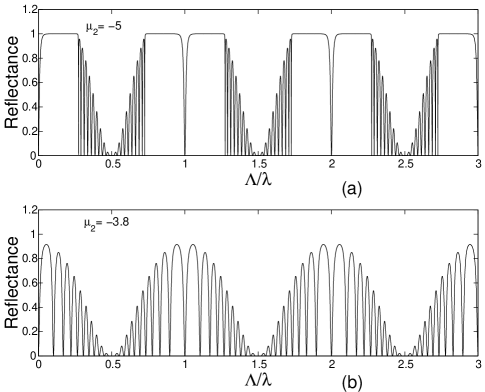
If the reflection coefficient for each interface is small, the contribution of the add-in-phased waves reflected from the first a few layers will not besignificant to the total reflection. The phases of the waves reflected from the later layers shift away quite much, e.g., larger than , from the Bragg condition (this is only possible when ) and thus the comparison analysis of and can not be applied for these waves. Therefore, when and the reflection coefficient for each interface is small, it may happens that the transparent condition dominates and consequently causes comparatively large transmission bands centered at wavelengths when both the transparent condition and the Bragg condition are satisfied. Fig. 3(b) shows such an example (note that the interface reflection becomes much smaller when is changed from to ). One can see that even in this case the reflectance increases steadily to a considerably large value (though less than ) when is quite near to .
Finally we consider the situation when the LHM is dispersive and/or lossy (as suggested in e.g. prl ). As long as the permittivity and permeability of the LHM vary little around a target frequency when both the transparent condition and the Bragg condition are satisfied, one can still observe the unusual narrow transmission band. As an example, we assume the following frequency dependence for the LHM parameters veselago ; pendry1 ; shelby ,
| (10) | |||
| (11) |
where is the analogue of the plasma frequency, is the analogue of the resonant frequency of a magnetic plasma, is the electronic resonant frequency and is the magnetic resonant frequency. Here is the frequency of the incident wave ( denotes the speed of light in vacuum).
We take as the target frequency and at this frequency. We assume that ( is the ratio of or to ), then we have
| (12) | |||
| (13) |
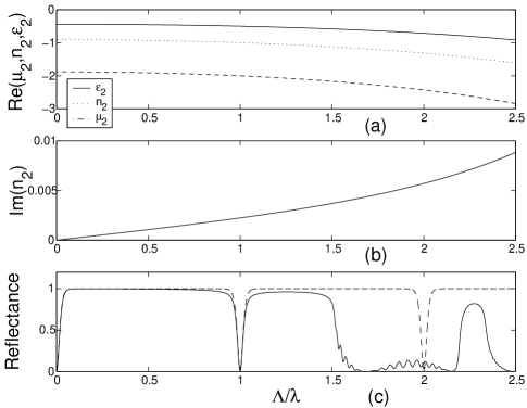
In this numerical example, we choose and . Then and change by about when changes by (see Fig. 4(a)). The imaginary part of the refraction index is about at . Both the dispersion and the loss are considerably large in this example. Nevertheless, the narrow transmission band at still exists (see Fig. 4(c)). The ideal (non-dispersive and lossless) case is also shown by the dashed line in Fig. 4(c) for comparison. The small decrease of the reflectance in the region is due to the loss (i.e., the imaginary part of the refractive index ; cf. the dotted line in Fig. 4(a)).
In conclusion, we have shown and explained the unusual narrow transmission bands as the competitive results of the Bragg condition and the transparent condition in a multi-layered structure consisting of alternate RHM and LHM layers. These unusual narrow transmission bands may exist regardless whether the optical length of the LHM layer cancels the optical length of the RHM layer or not. This unusual transmission property may disappear when the reflection coefficient for each interface is small and (i.e., the optical length of the LHM layer does not cancel the optical length of the RHM layer). The unusual transmission still exists even when the LHM is lossy or dispersive.
Acknowledgment. The partial support of National Natural Science Foundation of China (under a key project grant; grant number 90101024) is gratefully acknowledged. One of the authors (L. Wu) thanks Liu Liu and Zhuo Ye for their beneficial discussions.
References
- (1) V.G. Veselago, Sov. Phys. Usp. 10, 509 (1968).
- (2) D.R. Smith, W.J. Padilla, D.C. Vier, S.C. Nemat-Nasser, and S.Schultz, Phys. Rev. Lett. 84, 4184 (2000).
- (3) R.A. Shelby, D.R. Smith, S.C. Nemat-Nasser, and S. Schultz, Appl. Phys. Lett. 78, 489 (2001).
- (4) R.A. Shelby, D.R. Smith and S. Schultz, Science 292, 77 (2001).
- (5) J.B. Pendry, A.J. Holden, W.J. Stewart, and I. Younges, Phys. Rev. Lett. 76, 4773 (1996).
- (6) J.B. Pendry, A.J. Holden, D.J. Robbins, and W.J. Stewart, J. Phys.: Condens. Matter 10, 4785 (1998).
- (7) J. B. Pendry, Phys. Rev. Lett. 85, 3966 (2000).
- (8) J. Gerardin and A. Lakhtakia, Mirc. and Opt. Tech. Lett. 34, 409 (2002).
- (9) Z. M. Zhang and C. J. Fu, Appl. Phys. Lett. 80, 1097 (2001).
- (10) N. Garcia and M. Nieto-Vesperinas, Phys. Rev. Lett., 88, 207403 (2002).