Application of Volume diffraction grating for terahertz lasing in Volume FEL (VFEL)

V.G.Baryshevsky bar@inp.minsk.by    K.G.Batrakov batrakov@inp.minsk.by    V.I.Stolyarsky vist@inp.minsk.by Institute of Nuclear Problems, Belarusian State University, 11 Bobruiskaya Str., Minsk 220050, Belarus.
Abstract

The generation of induced radiation in volume resonator formed by metal threads is considered. It is shown that using of such volume diffraction grating allows increasing of lasing efficiency in terahertz range. The requirements on beam and grating parameters are obtained.

I Introduction

Generation of radiation in millimeter and far-infrared range with nonrelativistic and low-relativistic electron beams gives rise difficulties. Gyrotrons and cyclotron resonance facilities are used as sources in millimeter and sub-millimeter range, but for their operation magnetic field about several tens of kiloGauss (ωeHmcγsimilar-to𝜔𝑒𝐻𝑚𝑐𝛾\omega\sim\frac{eH}{mc}\gamma) is necessary. Slow-wave devices (TWT, BWT, orotrons)in this range require application of dense and thin (¡0.1 mm) electron beams, because only electrons passing near the slowing structure at the distance λβγ/(4π)absent𝜆𝛽𝛾4𝜋\leq\lambda\beta\gamma/(4\pi) can interact with electromagnetic wave effectively. It is difficult to guide thin beams near slowing structure with desired accuracy. And electrical endurance of resonator limits radiation power and density of acceptable electron beam. Conventional waveguide systems are essentially restricted by the requirement for transverse dimensions of resonator, which should not significantly exceed radiation wavelength. Otherwise, generation efficiency reduces abruptly due to excitation of plenty of modes.

The most of the above problems can be overpassed in VFEL. In VFEL the greater part of electron beam interacts with electromagnetic wave due to volume distributed interaction. Transverse dimensions of VFEL resonator could significantly exceed radiation wavelength D>>λmuch-greater-than𝐷𝜆D>>\lambda. In addition, electron beam and radiation power are distributed over the whole volume that is beneficial for electrical endurance of the system. Multi-wave Bragg dynamical diffraction provides mode discrimination in VFEL.

Dispersion equations, describing instability and threshold conditions of generation for VFEL were investigated in details in fer -mm . There were shown that threshold values of current can be significantly reduced in conditions of multi-wave Bragg diffraction. But there mainly relativistic and ultrarelativistic electron beams were considered. Essential distinctions appear at use of nonrelativistic and low-relativistic electrons. For example, in slow-wave devices radiation conditions can not be fulfilled simultaneously with conditions of Bragg diffraction if refraction index n<c/u𝑛𝑐𝑢n<c/u. Generation in spatially-periodic structure composed from dielectric threads was studied in exp for low-relativistic (300 keV)electron beam.

Present paper investigates instability of electron beam in volume diffraction structures composed from strained threads. There are frequency ranges, in which such systems can generate, and those in which they work as amplifiers. It should be mentioned that generation can occur even in one-periodic diffraction structure. In this case Bragg conditions are not fulfilled and back-wave is used for generation. Tuning of radiation frequency in such a system can be provided either by change of radiation angle or by grating rotation or by change of direction and value of electron beam velocity. Nonrelativistic and low-relativistic electron beams passing through such structures can generate in wide frequency range up to terahertz.

II Amplification and generation in diffraction structure

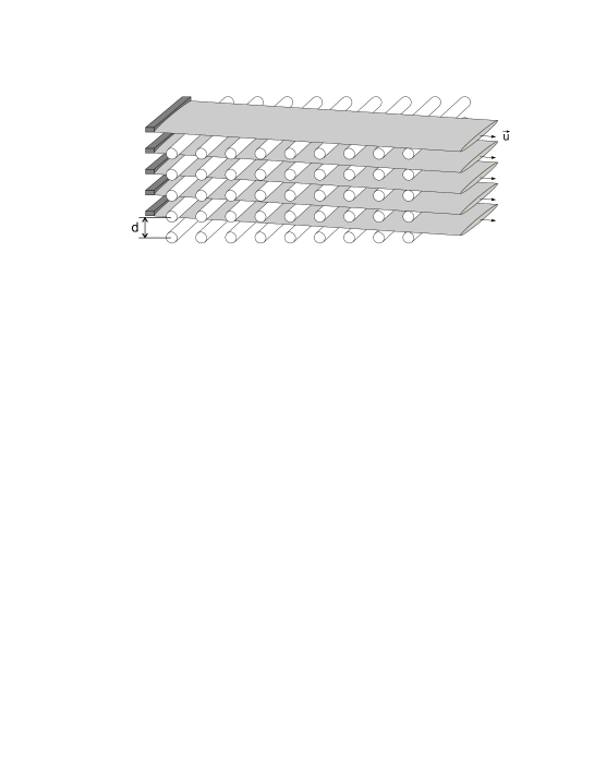
Let us consider an electron beam with velocity u𝑢\vec{u} passing through a periodic structure composed from either dielectric or metal threads (see Figure 1.)

Refer to caption


Figure 1: General view of Volume Free Electron Laser formed by metal threads with several sheet electron beams.

Fields, which appear at electron beam passing through a volume spatially-periodic medium are described by the following set of equations 3 :

DEω2χ1E1ω2χ2E2ω2χ3E3𝐷𝐸superscript𝜔2subscript𝜒1subscript𝐸1superscript𝜔2subscript𝜒2subscript𝐸2superscript𝜔2subscript𝜒3subscript𝐸3\displaystyle DE-\omega^{2}\chi_{1}E_{1}-\omega^{2}\chi_{2}E_{2}-\omega^{2}\chi_{3}E_{3}-... =\displaystyle= 00\displaystyle 0
ω2χ1E+D1E1ω2χ21E2ω2χ31E3superscript𝜔2subscript𝜒1𝐸subscript𝐷1subscript𝐸1superscript𝜔2subscript𝜒21subscript𝐸2superscript𝜔2subscript𝜒31subscript𝐸3\displaystyle-\omega^{2}\chi_{-1}E+D_{1}E_{1}-\omega^{2}\chi_{2-1}E_{2}-\omega^{2}\chi_{3-1}E_{3}-... =\displaystyle= 00\displaystyle 0 (1)
ω2χ2Eω2χ12E1+D2E2ω2χ12E1superscript𝜔2subscript𝜒2𝐸superscript𝜔2subscript𝜒12subscript𝐸1subscript𝐷2subscript𝐸2superscript𝜔2subscript𝜒12subscript𝐸1\displaystyle-\omega^{2}\chi_{-2}E-\omega^{2}\chi_{1-2}E_{1}+D_{2}E_{2}-\omega^{2}\chi_{1-2}E_{1}-... =\displaystyle= 0,0\displaystyle 0,

Set (1)is obtained by the use of Bloch representation for field

E(r;ω)=Eiexp{i(k+τi)r}𝐸𝑟𝜔subscript𝐸𝑖𝑖𝑘subscript𝜏𝑖𝑟\vec{E}(\vec{r};\omega)=\sum\vec{E}_{i}\exp\{i(\vec{k}+\vec{\tau}_{i})\vec{r}\}

and permittivity in a spatially-periodic medium (ε(r+an,ω)=ε(r,ω)𝜀𝑟subscript𝑎𝑛𝜔𝜀𝑟𝜔\varepsilon(\vec{r}+\vec{a}_{n},\omega)=\varepsilon(\vec{r},\omega))

ε(r,ω)=1+{τ}χτ(ω)exp(iτr),.𝜀𝑟𝜔1subscript𝜏subscript𝜒𝜏𝜔𝑖𝜏𝑟\varepsilon(\vec{r},\omega)=1+\sum_{\{\tau\}}\chi_{\tau}(\omega)\exp(i\vec{\tau}\vec{r}),.

τi={2πai1;2πbi2;2πci3}subscript𝜏𝑖2𝜋𝑎subscript𝑖12𝜋𝑏subscript𝑖22𝜋𝑐subscript𝑖3\vec{\tau}_{i}=\{\frac{2\pi}{a}i_{1};\frac{2\pi}{b}i_{2};\frac{2\pi}{c}i_{3}\} are the reciprocal lattice vectors, an=n1a+n2bsubscript𝑎𝑛subscript𝑛1𝑎subscript𝑛2𝑏\vec{a}_{n}=n_{1}\vec{a}+n_{2}\vec{b} +n3csubscript𝑛3𝑐+n_{3}\vec{c} are the translation vectors of periodic medium, i1÷i3subscript𝑖1subscript𝑖3i_{1}\div i_{3}, n1÷n3subscript𝑛1subscript𝑛3n_{1}\div n_{3} are the integer numbers. Dα=kα2c2ω2ε+χα(b)subscript𝐷𝛼superscriptsubscript𝑘𝛼2superscript𝑐2superscript𝜔2𝜀superscriptsubscript𝜒𝛼𝑏D_{\alpha}=k_{\alpha}^{2}c^{2}-\omega^{2}\varepsilon+\chi_{\alpha}^{(b)} , kα=k+ταsubscript𝑘𝛼𝑘subscript𝜏𝛼\vec{k}_{\alpha}=\vec{k}+\vec{\tau}_{\alpha} is the wave vector of diffracted photon, χα(b)superscriptsubscript𝜒𝛼𝑏\chi_{\alpha}^{(b)} is the part dielectric susceptibility, caused by the presence of electron beam:

χα(b)superscriptsubscript𝜒𝛼𝑏\displaystyle\chi_{\alpha}^{(b)} =\displaystyle= 1γ(ωb/ω)2(𝐮𝐞α/c)2×kα2c2ω2(ωkαu)21𝛾superscriptsubscript𝜔𝑏𝜔2superscriptsuperscript𝐮𝐞𝛼𝑐2superscriptsubscript𝑘𝛼2superscript𝑐2superscript𝜔2superscript𝜔subscript𝑘𝛼𝑢2\displaystyle\frac{1}{\gamma}(\omega_{b}/\omega)^{2}(\mathbf{ue}^{\alpha}/c)^{2}\times\frac{k_{\alpha}^{2}c^{2}-\omega^{2}}{(\omega-\vec{k}_{\alpha}\vec{u})^{2}}
”cold” beam limit,
χα(b)superscriptsubscript𝜒𝛼𝑏\displaystyle\chi_{\alpha}^{(b)} =\displaystyle= iπγ(ωb/ω)2(𝐮𝐞α/c)2×kα2c2ω2δα2xαtexp[(xαt)2]𝑖𝜋𝛾superscriptsubscript𝜔𝑏𝜔2superscriptsuperscript𝐮𝐞𝛼𝑐2superscriptsubscript𝑘𝛼2superscript𝑐2superscript𝜔2superscriptsubscript𝛿𝛼2superscriptsubscript𝑥𝛼𝑡superscriptsuperscriptsubscript𝑥𝛼𝑡2\displaystyle-\frac{i\sqrt{\pi}}{\gamma}(\omega_{b}/\omega)^{2}(\mathbf{ue}^{\alpha}/c)^{2}\times\frac{k_{\alpha}^{2}c^{2}-\omega^{2}}{\delta_{\alpha}^{2}}x_{\alpha}^{t}\exp[-(x_{\alpha}^{t})^{2}]
”hot” beam limit.

xαt=(ωkαu)/2δαsuperscriptsubscript𝑥𝛼𝑡𝜔subscript𝑘𝛼𝑢2subscript𝛿𝛼x_{\alpha}^{t}=(\omega-\vec{k}_{\alpha}\vec{u})/\sqrt{2}\delta_{\alpha}, δα2=(kα12Ψ12+kα22Ψ22+kα32Ψ32)u2superscriptsubscript𝛿𝛼2superscriptsubscript𝑘𝛼12superscriptsubscriptΨ12superscriptsubscript𝑘𝛼22superscriptsubscriptΨ22superscriptsubscript𝑘𝛼32superscriptsubscriptΨ32superscript𝑢2\delta_{\alpha}^{2}=(k_{\alpha 1}^{2}\Psi_{1}^{2}+k_{\alpha 2}^{2}\Psi_{2}^{2}+k_{\alpha 3}^{2}\Psi_{3}^{2})u^{2} and Ψ=Δu/uΨΔ𝑢𝑢\vec{\Psi}=\Delta\vec{u}/u spread of electron’s velocities in a beam. Values of χα(b)superscriptsubscript𝜒𝛼𝑏\chi_{\alpha}^{(b)} in (II) are cited for two opposite limits. First case is described by the inequality |ωkαu|δαmuch-greater-than𝜔subscript𝑘𝛼𝑢subscript𝛿𝛼|\omega-\vec{k}_{\alpha}\vec{u}|\gg\delta_{\alpha} and corresponds to the so called hydrodynamic or ”cold” beam limit. In this case all electrons participate in interaction with electromagnetic wave. Kinetic or ”hot” beam limit |ωkαu|δαprecedes-or-equivalent-to𝜔subscript𝑘𝛼𝑢subscript𝛿𝛼|\omega-\vec{k}_{\alpha}\vec{u}|\precsim\delta_{\alpha} supposes that only part of electrons participates in interaction process.

As it was mentioned above, synchronism conditions are incompatible with conditions of dynamic diffraction for nonrelativistic and low-relativistic electron beams. In this case generation can appear due to transition radiation in periodic medium and electron beam interacts with slightly coupled component corresponding to the wave vector kτ=k+τsubscript𝑘𝜏𝑘𝜏\vec{k}_{\tau}=\vec{k}+\vec{\tau}. According to (1) the dispersion equation, which describes instability of electron beam is as follows:

(k2c2ω2ε)(kτ2c2ω2ε+χτ(b))ω2χτχτ=0.superscript𝑘2superscript𝑐2superscript𝜔2𝜀superscriptsubscript𝑘𝜏2superscript𝑐2superscript𝜔2𝜀superscriptsubscript𝜒𝜏𝑏superscript𝜔2subscript𝜒𝜏subscript𝜒𝜏0(k^{2}c^{2}-\omega^{2}\varepsilon)(k_{\tau}^{2}c^{2}-\omega^{2}\varepsilon+\chi_{\tau}^{(b)})-\omega^{2}\chi_{\tau}\chi_{-\tau}=0. (3)

As synchronism conditions are incompatible with Bragg those, then k2kτ2superscript𝑘2superscriptsubscript𝑘𝜏2k^{2}\neq k_{\tau}^{2} in the instability range. At the same time two different types of instability exist depending on radiation frequency. Amplification takes place when electron beam is in synchronism with electromagnetic component k+τ𝑘𝜏\vec{k}+\vec{\tau}, which has positive projection kzsubscript𝑘𝑧k_{z}. If projection kzsubscript𝑘𝑧k_{z} is negative and generation threshold is reached, then generation occurs. In the first case radiation propagates along the transmitted wave, which has positive projection of group velocity vz=c2kz(0)ωsubscript𝑣𝑧superscript𝑐2superscriptsubscript𝑘𝑧0𝜔v_{z}=\frac{c^{2}k_{z}^{(0)}}{\omega} (kz(0)=ω2εk2superscriptsubscript𝑘𝑧0superscript𝜔2𝜀superscriptsubscript𝑘perpendicular-to2k_{z}^{(0)}=\sqrt{\omega^{2}\varepsilon-k_{\perp}^{2}}), and beam disturbance moves along it. In the second case the group velocity has negative projection vz=c2kz(0)ωsubscript𝑣𝑧superscript𝑐2superscriptsubscript𝑘𝑧0𝜔v_{z}=-\frac{c^{2}k_{z}^{(0)}}{\omega} and radiation propagates along back-wave and electromagnetic wave comes from the range of the greatest beam disturbance to the place, where electrons come into the interaction area. For one-dimensional structure such mechanism is realized in backward-wave tube.

Dispersion equation, which describes the roots, corresponding interaction of electron beam with electromagnetic wave at k2kτ2superscript𝑘2superscriptsubscript𝑘𝜏2k^{2}\neq k_{\tau}^{2} can be rewritten as:

uz2(kza1)2(kzkz(0))(kz+kz(0))=aωL2(ueτ)2ω4rc4(kτ2c2ω2ε0),superscriptsubscript𝑢𝑧2superscriptsubscript𝑘𝑧subscript𝑎12subscript𝑘𝑧superscriptsubscript𝑘𝑧0subscript𝑘𝑧superscriptsubscript𝑘𝑧0𝑎superscriptsubscript𝜔𝐿2superscript𝑢superscript𝑒𝜏2superscript𝜔4𝑟superscript𝑐4superscriptsubscript𝑘𝜏2superscript𝑐2superscript𝜔2subscript𝜀0u_{z}^{2}\left(k_{z}-a_{1}\right)^{2}(k_{z}-k_{z}^{(0)})(k_{z}+k_{z}^{(0)})=-\frac{a\omega_{L}^{2}(\vec{u}\vec{e}^{\tau})^{2}\omega^{4}r}{c^{4}\left(k_{\tau}^{2}c^{2}-\omega^{2}\varepsilon_{0}\right)}, (4)

where a1=ωkuuzτzsubscript𝑎1𝜔subscript𝑘perpendicular-tosubscript𝑢perpendicular-tosubscript𝑢𝑧subscript𝜏𝑧a_{1}=\frac{\omega-\vec{k}_{\perp}\vec{u}_{\perp}}{u_{z}}-\tau_{z}. For amplification case (4) gives for increment of instability:

Imkz=32f,𝐼𝑚superscriptsubscript𝑘𝑧32𝑓Imk_{z}^{\prime}=-\frac{\sqrt{3}}{2}f, (5)

where f=aωL2(ueτ)2ω4r2kz(0)c4uz2(kτ2c2ω2ε0)3𝑓3𝑎superscriptsubscript𝜔𝐿2superscript𝑢superscript𝑒𝜏2superscript𝜔4𝑟2superscriptsubscript𝑘𝑧0superscript𝑐4superscriptsubscript𝑢𝑧2superscriptsubscript𝑘𝜏2superscript𝑐2superscript𝜔2subscript𝜀0f=\sqrt[3]{\frac{a\omega_{L}^{2}(\vec{u}\vec{e}^{\tau})^{2}\omega^{4}r}{2k_{z}^{(0)}c^{4}u_{z}^{2}\left(k_{\tau}^{2}c^{2}-\omega^{2}\varepsilon_{0}\right)}}, if condition 2kzfω2χ0"c2much-greater-than2superscriptsubscript𝑘𝑧𝑓superscript𝜔2subscript𝜒0"superscript𝑐22k_{z}^{\prime}f\gg\frac{\omega^{2}\chi_{0}"}{c^{2}} is fulfilled. In case 2kzfω2χ0"c2much-less-than2superscriptsubscript𝑘𝑧𝑓superscript𝜔2subscript𝜒0"superscript𝑐22k_{z}^{\prime}f\ll\frac{\omega^{2}\chi_{0}"}{c^{2}} dissipative instability evolves. Its increment is

Imkz=cωkz(0)f3χ0.𝐼𝑚subscript𝑘𝑧𝑐𝜔superscriptsubscript𝑘𝑧0superscript𝑓3subscript𝜒0Imk_{z}=-\frac{c}{\omega}\sqrt{\frac{k_{z}^{(0)}f^{3}}{\chi_{0}}}. (6)

If inequalities kz`22kzkz`much-greater-thansuperscriptsubscript𝑘𝑧`22subscript𝑘𝑧superscriptsubscript𝑘𝑧`k_{z}^{`2}\gg 2k_{z}k_{z}^{`} and kz`2ω2χ0"c2much-greater-thansuperscriptsubscript𝑘𝑧`2superscript𝜔2subscript𝜒0"superscript𝑐2k_{z}^{`2}\gg\frac{\omega^{2}\chi_{0}"}{c^{2}} are fulfilled, spatial increment of instability can be expressed as:

Imkz`=(aωL2(ueτ)2ω4rc4(kτ2c2ω2ε0)uz2)1/4,𝐼𝑚superscriptsubscript𝑘𝑧`superscript𝑎superscriptsubscript𝜔𝐿2superscript𝑢superscript𝑒𝜏2superscript𝜔4𝑟superscript𝑐4superscriptsubscript𝑘𝜏2superscript𝑐2superscript𝜔2subscript𝜀0superscriptsubscript𝑢𝑧214Imk_{z}^{`}=-\left(\frac{a\omega_{L}^{2}(\vec{u}\vec{e}^{\tau})^{2}\omega^{4}r}{c^{4}\left(k_{\tau}^{2}c^{2}-\omega^{2}\varepsilon_{0}\right)u_{z}^{2}}\right)^{1/4}, (7)

but parameters providing dependence (7) correspond to the conversion from amplification to generation regime. For Compton instability (at proper electron beam density) this situation takes place at kz(0)0superscriptsubscript𝑘𝑧00k_{z}^{(0)}\approx 0

Frequency of amplified radiation is defined as:

ω=τu1βxηxβyηyβzεηx2ηy2.𝜔𝜏𝑢1subscript𝛽𝑥subscript𝜂𝑥subscript𝛽𝑦subscript𝜂𝑦subscript𝛽𝑧𝜀superscriptsubscript𝜂𝑥2superscriptsubscript𝜂𝑦2\omega=\frac{\vec{\tau}\vec{u}}{1-\beta_{x}\eta_{x}-\beta_{y}\eta_{y}-\beta_{z}\sqrt{\varepsilon-\eta_{x}^{2}-\eta_{y}^{2}}}. (8)

Instability in generation regime is described by the temporal increment and can not be described by the spatial that. Increment of absolute instability can be found solving the equation

Imkz(+)(ω)=Imkz()(ω)𝐼𝑚superscriptsubscript𝑘𝑧𝜔𝐼𝑚superscriptsubscript𝑘𝑧𝜔Imk_{z}^{(+)}(\omega)=Imk_{z}^{(-)}(\omega) (9)

with respect to imaginary part of ω𝜔\omega. Roots of (4) are expressed as:

kz1()=a1a1+kz(0)3+A+Bsuperscriptsubscript𝑘𝑧1subscript𝑎1subscript𝑎1superscriptsubscript𝑘𝑧03𝐴𝐵\displaystyle k_{z1}^{(-)}=a_{1}-\frac{a_{1}+k_{z}^{(0)}}{3}+A+B (10)
kz2,3(+)=a1a1+kz(0)3A+B2±iAB23,superscriptsubscript𝑘𝑧23plus-or-minussubscript𝑎1subscript𝑎1superscriptsubscript𝑘𝑧03𝐴𝐵2𝑖𝐴𝐵23\displaystyle k_{z2,3}^{(+)}=a_{1}-\frac{a_{1}+k_{z}^{(0)}}{3}-\frac{A+B}{2}\pm i\frac{A-B}{2}\sqrt{3},

where

A=f32(a1+kz(0)3)3+f64f3(a1+kz(0))33𝐴3superscript𝑓32superscriptsubscript𝑎1superscriptsubscript𝑘𝑧033superscript𝑓64superscript𝑓3superscriptsubscript𝑎1superscriptsubscript𝑘𝑧03\displaystyle A=\sqrt[3]{\frac{f^{3}}{2}-\left(\frac{a_{1}+k_{z}^{(0)}}{3}\right)^{3}+\sqrt{\frac{f^{6}}{4}-f^{3}(a_{1}+k_{z}^{(0)})^{3}}}
B=f32(a1+kz(0)3)3f64f3(a1+kz(0))33.𝐵3superscript𝑓32superscriptsubscript𝑎1superscriptsubscript𝑘𝑧033superscript𝑓64superscript𝑓3superscriptsubscript𝑎1superscriptsubscript𝑘𝑧03\displaystyle B=\sqrt[3]{\frac{f^{3}}{2}-\left(\frac{a_{1}+k_{z}^{(0)}}{3}\right)^{3}-\sqrt{\frac{f^{6}}{4}-f^{3}(a_{1}+k_{z}^{(0)})^{3}}}.

Calculated dependence of temporal increment on parameter of detuning is presented in Fig.2.

Refer to caption


Figure 2: Calculated dependence of temporal increment on detuning parameter.

Axes in Fig.2 are denoted as: d=a1+kz(0)f𝑑subscript𝑎1superscriptsubscript𝑘𝑧0𝑓d=\frac{a_{1}+k_{z}^{(0)}}{f}, n=ω"uz+2ωω"ε0+ω2χ0"c2kz(0)f𝑛𝜔"subscript𝑢𝑧2𝜔𝜔"subscript𝜀0superscript𝜔2subscript𝜒0"superscript𝑐2superscriptsubscript𝑘𝑧0𝑓n=\frac{\frac{\omega"}{u_{z}}+\frac{2\omega\omega"\varepsilon_{0}+\omega^{2}\chi_{0}"}{c^{2}k_{z}^{(0)}}}{f}. It follows from Fig.2 that at certain value of parameter of detuning:

a1+kz(0)f0.3subscript𝑎1superscriptsubscript𝑘𝑧0𝑓0.3\frac{a_{1}+k_{z}^{(0)}}{f}\approx-0.3 (11)

increment of instability has maximum peak

ω"uz+2ωω"ε0+ω2χ0"c2kz(0)f0.98.𝜔"subscript𝑢𝑧2𝜔𝜔"subscript𝜀0superscript𝜔2subscript𝜒0"superscript𝑐2superscriptsubscript𝑘𝑧0𝑓0.98\frac{\frac{\omega"}{u_{z}}+\frac{2\omega\omega"\varepsilon_{0}+\omega^{2}\chi_{0}"}{c^{2}k_{z}^{(0)}}}{f}\approx 0.98. (12)

Increment of absolute instability can be found from (12). It is easy to see that absolute instability can evolve if current exceed start value, which is determined by dissipation. Amplification regime has no threshold and deciding influence of dissipation causes dissipative instability (6).

Frequencies, corresponding to generation regime, are defined by the expression different from (8):

ω=τu1βxηxβyηy+βzεηx2ηy2.𝜔𝜏𝑢1subscript𝛽𝑥subscript𝜂𝑥subscript𝛽𝑦subscript𝜂𝑦subscript𝛽𝑧𝜀superscriptsubscript𝜂𝑥2superscriptsubscript𝜂𝑦2\omega=\frac{\vec{\tau}\vec{u}}{1-\beta_{x}\eta_{x}-\beta_{y}\eta_{y}+\beta_{z}\sqrt{\varepsilon-\eta_{x}^{2}-\eta_{y}^{2}}}. (13)

Thus, it follows from (8, 13) that change of radiation angle causes smooth frequency tuning. At that, generation frequencies are less than those corresponding to amplification regime. Hence, using system as amplifier one should add dispersion elements in it to raise dissipation in frequency range, in which generation occurs.

Use of Bragg multiwave distributed feedback increases generation efficiency and provides discrimination of generated modes. If conditions of synchronism and Bragg conditions are not fulfilled simultaneously, diffraction structures with two different periods can be applied nonrel . The first of them provides synchronism of electromagnetic wave with electron beam ωku=τ1u𝜔𝑘𝑢subscript𝜏1𝑢\omega-\vec{k}\vec{u}=\vec{\tau}_{1}\vec{u}, where τ1subscript𝜏1\vec{\tau}_{1} is the reciprocal lattice vector of this structure. The second diffraction structure evolves distributed Bragg coupling |k||k+τj|𝑘𝑘subscript𝜏𝑗|\vec{k}|\approx|\vec{k}+\vec{\tau}_{j}|, τjsubscript𝜏𝑗\vec{\tau}_{j} (j=2÷n𝑗2𝑛j=2\div n)are the reciprocal lattice vectors of the second structure. Conditions of synchronism and Bragg conditions can be fulfilled even for one diffraction structure, because diffraction structure with one period has unlimited set of reciprocal lattice vectors. Then reciprocal lattice vectors providing synchronism and Bragg conditions are significantly different in value.

It follows from (1) that dispersion equation for distributed feedback supplied by two-wave diffraction with one low coupled wave is expressed as:

F3(k;k1;k2)=χ1(b)F2(k;k2)subscript𝐹3𝑘subscript𝑘1subscript𝑘2superscriptsubscript𝜒1𝑏subscript𝐹2𝑘subscript𝑘2F_{3}(\vec{k};\vec{k}_{1};\vec{k}_{2})=-\chi_{1}^{(b)}F_{2}(\vec{k};\vec{k}_{2}) (14)

where:

F3(k;k1;k2)subscript𝐹3𝑘subscript𝑘1subscript𝑘2\displaystyle F_{3}(\vec{k};\vec{k}_{1};\vec{k}_{2}) =\displaystyle= (k2c2ω2ε)(k12c2ω2ε)(k22c2ω2ε)limit-fromsuperscript𝑘2superscript𝑐2superscript𝜔2𝜀superscriptsubscript𝑘12superscript𝑐2superscript𝜔2𝜀superscriptsubscript𝑘22superscript𝑐2superscript𝜔2𝜀\displaystyle(k^{2}c^{2}-\omega^{2}\varepsilon)(k_{1}^{2}c^{2}-\omega^{2}\varepsilon)(k_{2}^{2}c^{2}-\omega^{2}\varepsilon)-
ω4(k2c2ω2ε)χ12χ21ω4(k12c2ω2ε)χ2χ2superscript𝜔4superscript𝑘2superscript𝑐2superscript𝜔2𝜀subscript𝜒12subscript𝜒21superscript𝜔4superscriptsubscript𝑘12superscript𝑐2superscript𝜔2𝜀subscript𝜒2subscript𝜒2\displaystyle\omega^{4}(k^{2}c^{2}-\omega^{2}\varepsilon)\chi_{1-2}\chi_{2-1}-\omega^{4}(k_{1}^{2}c^{2}-\omega^{2}\varepsilon)\chi_{2}\chi_{-2}
ω4(k22c2ω2ε)χ1χ1ω6(χ1χ2χ21+χ2χ1χ12)superscript𝜔4superscriptsubscript𝑘22superscript𝑐2superscript𝜔2𝜀subscript𝜒1subscript𝜒1superscript𝜔6subscript𝜒1subscript𝜒2subscript𝜒21subscript𝜒2subscript𝜒1subscript𝜒12\displaystyle-\omega^{4}(k_{2}^{2}c^{2}-\omega^{2}\varepsilon)\chi_{1}\chi_{-1}-\omega^{6}(\chi_{1}\chi_{-2}\chi_{2-1}+\chi_{2}\chi_{-1}\chi_{1-2})
F2(k;k2)subscript𝐹2𝑘subscript𝑘2\displaystyle F_{2}(\vec{k};\vec{k}_{2}) =\displaystyle= (k2c2ω2ε)(k22c2ω2ε)ω4χ2χ2.superscript𝑘2superscript𝑐2superscript𝜔2𝜀superscriptsubscript𝑘22superscript𝑐2superscript𝜔2𝜀superscript𝜔4subscript𝜒2subscript𝜒2\displaystyle(k^{2}c^{2}-\omega^{2}\varepsilon)(k_{2}^{2}c^{2}-\omega^{2}\varepsilon)-\omega^{4}\chi_{2}\chi_{-2}.

(14) is derived with the assumption that synchronism conditions are fulfilled for reciprocal lattice vector τ1subscript𝜏1\vec{\tau}_{1} (ω(k+τ1)u0𝜔𝑘subscript𝜏1𝑢0\omega-(\vec{k}+\vec{\tau}_{1})\vec{u}\approx 0), while two-wave diffraction evolves at planes with reciprocal lattice vector τ2subscript𝜏2\vec{\tau}_{2} (|k||k+τ2|𝑘𝑘subscript𝜏2|\vec{k}|\approx|\vec{k}+\vec{\tau}_{2}|). Threshold conditions of generation and increment of temporal instability for the latter geometry were obtained in nonrel :

ω′′=ω2(1β){G(γ0unu)316π3n2β(kχ2L)2kLχ0′′(1β±βr′′|χ2|χ0′′)}superscript𝜔′′𝜔21𝛽𝐺superscriptsubscript𝛾0𝑢𝑛𝑢316superscript𝜋3superscript𝑛2𝛽superscript𝑘subscript𝜒2subscript𝐿2𝑘subscript𝐿superscriptsubscript𝜒0′′plus-or-minus1𝛽𝛽superscript𝑟′′subscript𝜒2superscriptsubscript𝜒0′′\omega^{\prime\prime}=\frac{\omega}{2(1-\beta)}\{G-(\frac{\gamma_{0}u}{\vec{n}\vec{u}})^{3}\frac{16\pi^{3}n^{2}}{-\beta(k\chi_{2}L_{\ast})^{2}kL_{\ast}}-\chi_{0}^{\prime\prime}(1-\beta\pm\sqrt{-\beta}\frac{r^{\prime\prime}}{|\chi_{2}|\chi_{0}^{\prime\prime}})\} (15)

where:

G𝐺\displaystyle G =\displaystyle= (kL)2π2n24γ(ωbω)2(ue1nu)2(l1+χ0)superscript𝑘subscript𝐿2superscript𝜋2superscript𝑛24𝛾superscriptsubscript𝜔𝑏𝜔2superscript𝑢subscript𝑒1𝑛𝑢2subscript𝑙1subscript𝜒0\displaystyle(kL_{\ast})^{2}\frac{\pi^{2}n^{2}}{4\gamma}(\frac{\omega_{b}}{\omega})^{2}(\frac{\vec{u}\vec{e}_{1}}{\vec{n}\vec{u}})^{2}(l_{1}+\chi_{0})
×lχ12χ21+l2χ1χ1+χ1χ2χ21+χ2χ1χ12l12f(y),absent𝑙subscript𝜒12subscript𝜒21subscript𝑙2subscript𝜒1subscript𝜒1subscript𝜒1subscript𝜒2subscript𝜒21subscript𝜒2subscript𝜒1subscript𝜒12superscriptsubscript𝑙12𝑓𝑦\displaystyle\times\frac{l\chi_{1-2}\chi_{2-1}+l_{2}\chi_{1}\chi_{-1}+\chi_{1}\chi_{-2}\chi_{2-1}+\chi_{2}\chi_{-1}\chi_{1-2}}{l_{1}^{2}}f(y),

l=k02c2ω2εω2𝑙superscriptsubscript𝑘02superscript𝑐2superscript𝜔2𝜀superscript𝜔2l=\frac{k_{0}^{2}c^{2}-\omega^{2}\varepsilon}{\omega^{2}}, l1=(k0+τ1)2c2ω2εω2subscript𝑙1superscriptsubscript𝑘0subscript𝜏12superscript𝑐2superscript𝜔2𝜀superscript𝜔2l_{1}=\frac{(\vec{k}_{0}+\vec{\tau}_{1})^{2}c^{2}-\omega^{2}\varepsilon}{\omega^{2}}, l2=(k0+τ2)2c2ω2εω2.subscript𝑙2superscriptsubscript𝑘0subscript𝜏22superscript𝑐2superscript𝜔2𝜀superscript𝜔2l_{2}=\frac{(\vec{k}_{0}+\vec{\tau}_{2})^{2}c^{2}-\omega^{2}\varepsilon}{\omega^{2}}. Condition ω′′=0superscript𝜔′′0\omega^{\prime\prime}=0 in (15) defines the start current of generation. Threshold conditions for s-wave diffraction is converted to:

G(s)=as3(kχL)2skL+χ0′′bs.superscript𝐺𝑠superscriptsubscript𝑎𝑠3superscript𝑘𝜒subscript𝐿2𝑠𝑘subscript𝐿superscriptsubscript𝜒0′′subscript𝑏𝑠G^{(s)}=\frac{a_{s}^{3}}{(k\chi L_{\ast})^{2s}kL_{\ast}}+\chi_{0}^{\prime\prime}b_{s}. (16)

For developed dynamic diffraction, when k|χ|L1much-greater-than𝑘𝜒subscript𝐿1k|\chi|L_{\ast}\gg 1, either generation start current or length of generation zone at certain current value can be reduced.

Each Bragg condition holds one of free parameters. For example, for certain geometry and electron beam velocity two conditions for 3-wave diffraction entirely determine transverse components of wave vector kxsubscript𝑘𝑥k_{x} and kysubscript𝑘𝑦k_{y}, and therefore generation frequency (see (8, 13)). Hence, volume diffraction system provides mode discrimination due to multiwave diffraction.

III     Discussion.

The above results affirm that volume diffraction structure provides both amplification and generation regimes even in the absence of dynamic diffraction. In latter case generation evolves with backward-wave similarly backward-wave tube. Frequency in such structure is changed smoothly either at smooth variation of radiation angle (variation of kxsubscript𝑘𝑥k_{x} and kysubscript𝑘𝑦k_{y}) or at rotation of diffraction grating or electron beam (change of τu𝜏𝑢\vec{\tau}\vec{u})(see (8), (13)). For certain geometry and reciprocal lattice vector amplification corresponds higher frequencies then generation. Rotation of either diffraction grating or electron beam also changes value of boundary frequency, which separates generation and amplification ranges. Use of multiwave distributed feedback owing to Bragg diffraction, let either to increase generation efficiency or to reduce length of interaction area ((15), (14)). In this case generation is available with both backward and following waves.

In particular, the proposed volume structure can be used for generation of sub-millimeter radiation by accelerator LIU-3000. Parameters of this setup: electron beam energy E=800𝐸800E=800 keV, beam current I=100÷200𝐼100200I=100\div 200 A. To generate radiation with wavelength 0.3 mm in such a system volume structure composed from strained threads should has period similar-to\sim 2 mm, and period of diffraction grating providing Bragg coupling is similar-to\sim 0.16 mm.


References

  • (1) V.G.Baryshevsky, I.D.Feranchuk Phys.Let 102A,141,(1984).
  • (2) V.G.Baryshevsky, K.G.Batrakov, I.Ya.Dubovskaya Journ.Phys.D 24,1250,(1991).
  • (3) V.G.Baryshevsky, K.G.Batrakov, I.Ya.Dubovskaya NIM A 358, 493,(1995).
  • (4) V.G.Baryshevsky, K.G.Batrakov, I.Ya.Dubovskaya, S.Sytova NIM A 358,508,(1995).
  • (5) V.G.Baryshevsky, K.G.Batrakov, I.Ya.Dubovskaya, V.A.Karpovich, V.N.Rodionova, NIM A 393, p. 71-75, 1997.
  • (6) V.G.Baryshevsky, K.G.Batrakov, V.I.Stolyarsky Proceedings of 21 FEL Conference, p. 37-38, 1999.