Use of Dynamical Undulator Mechanism to Produce Short Wavelength Radiation in Volume FEL (VFEL)
Abstract
VFEL lasing in system with dynamical undulator is described. In this system radiation with longer wavelength creates the undulator for lasing on shorter wavelength. Two diffraction gratings with different spatial periods form VFEL resonator. The grating with longer period pumps the resonator by radiation of longer wavelength to provide necessary amplitude of undulator field. The grating with shorter period makes mode selection for radiation of shorter wavelength. Lasing of such a system in terahertz frequency range is discussed.
I
Introduction
The development of powerful electromagnetic generators with frequency tuning in millimeter, sub-millimeter and terahertz ranges using low-relativistic and non-relativistic electron beams is quite perspective for numerous applications. In such devices as TWT, BWT and orotrons generation of radiation with a wavelength requires application of diffraction structures with period . Only electrons passing near the slowing structure at the distance
| (1) |
interact with electromagnetic wave effectively. In (1) , is the Lorentz factor of electron. From (1) it follows, that generation of short-wave radiation for non-relativistic and low-relativistic electrons requires application of extremely thin and dense electron beams. Gyrotrons and undulator systems, in which an electron beam interacts with an electromagnetic wave in the whole area occupied by magnetic field, has no such drawback. Gyrotrons and cyclotron resonance facilities are used as radiation sources in millimeter and sub-millimeter range, but their operation requires magnetic field of about several tens of kiloGauss (). Applying undulator systems for generation of short-wave radiation gives rise a problem of manufacture of undulators with small period. For example, generation of radiation with the wavelength mm at the beam energy KeV - MeV requires to use undulator with period cm. This is extremely complicated problem. Much more rigid requirements arise in terahertz range. So even for generation in longwave boundary of terahertz range the undulator period should be mm (for KeV). Nowadays such requirement looks quite fantastic. For radiation in millimeter and sub-millimeter range it is possible to use mechanism of Compton scattering of an electromagnetic wave by an electron beam. Usually it is considered, that pumping wave emerges from outside. But, radiation generated in a system also can play the role of a pumping wave. If Q-factor of resonator is high enough, then the radiation power is accumulated in resonator and can act as undulator dynwig .
Such two-stage system (dynamic wiggler) can be used to soluve several problems simultaneously: 1) it allows to obtain radiation of shorter wavelength ( , where is the wavelength of a pumping wave. For example, if electron beam has the energy the frequency increasef in times;
2) provides volume character of interaction of an electron beam with an electromagnetic wave for non-relativistic beam (lorentz factor ()), for which dynamic wiggler can not allow considerable increase of radiation frequency.
For generation mechanisms based on slowing of electromagnetic wave (Cherenkov, Smith-Purcell, TWT, quasi-Cherenkov) electron beam interacts with evanescent component of electromagnetic wave (as it was noted above), therefore, only electrons, passing at the distances (1) over slowing structures, can radiate. Then, at the first stage, the fraction of electron beam participates in creating of dynamic wiggler. All electrons interact with the signal wave on the second stage.
Use of volume FEL principles extends advantages of the two-stage generation scheme and, in particular, allows to tune smoothly the period of dynamic wiggler by diffraction grating rotation. There is possibility of smooth tuning of frequency of both the pump wave and the signal wave by smooth variation of geometrical parameters of volume diffraction gratings, or by its rotation. Moreover, use of VFEL allows to create dynamic wiggler in large volume, that represents a great problem for static wiggler.
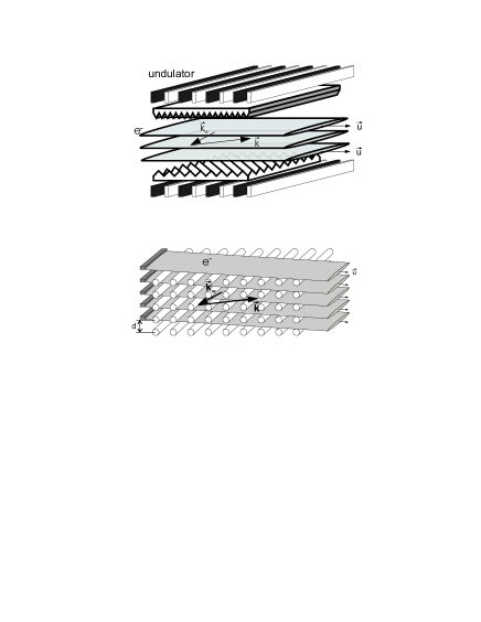
This scheme can be realized by the use of resonator formed by several diffraction gratings with different spatial periods two_periods . Smooth variation of geometrical parameters of volume diffraction gratings provides smooth variation of frequency of pumping and signal waves. Two possible realizations of dynamic wiggler on the basis of VFEL are represented on Figure 1. Dynamic wiggler with undulator mechanism of the first stage is depicted in the upper part of that figure. In this case the the pumping wave with the vector and frequency is formed by undulator with period . The wave with frequency is generated by the created dynamic wiggler during second stage. The distributed feedback is provided by two diffraction grating with different periods (one diffraction grating provides distributed feedback for pumping wave and another for signal one ). The dynamic wiggler generated by volume grating formed by threads is shown in the lower part of Figure 1. The generation in VFEL evolves in large volume with dimensions much exceeding wavelength of radiation that increases electrical endurance of resonator (due to distribution of electromagnetic power and electron beam over large volume). This peculiarity of VFEL is extremely essential for generation of powerful and super-powerful pulses of electromagnetic radiation. The mode discrimination in such oversized system is carried out by the multiwave dynamic diffraction basis .
II Deriving of the basic expressions for electron beam instability in a pumping wave in conditions of multiwave diffraction.
There are two stages in the generation scheme proposed above: a)generation of dynamic wiggler in a system with two-dimensional (three-dimensional) grating ; b) generation of radiation by an electron beam interacting with dynamic wiggler appeared on stage a). Let’s consider stage a). The diffraction grating providing non one-dimensional distributed feedback is used to evolve dynamic wiggler. Smooth variation of diffraction geometry of this diffraction grating yields smooth variation of dynamic wiggler parameters. The electromagnetic field of wiggler rises with time , where is the frequency of a pump wave. The Q-factor of resonator for frequency should be sufficient to create a magnetic field amplitude about Gs - KGs. It follows from the energy balance equation in resonator ( is the power of pump wave formed by an electron beam ) that , where is the cavity volume, is the amplitude of a magnetic field of dynamic wiggler. When the pump field achieves necessary magnitude, the stage b) begins. The created pump wave acts as undulator during this stage. Non-one-dimensional distributed feedback can also be realized for the signal wave. Dynamics of a signal electromagnetic wave and an electron beam in the system ”volume diffraction grating + pump electromagnetic wave ” in this case is described by equations
| (2) | |||||
In (2) , is the wave vector of diffracted wave in the field of volume grating , is the part of dielectric susceptibility corresponding to interaction of an electron beam with radiation
| ”cold” beam limit, | ||||
| ”hot” beam limit. |
and are the wave vectors, frequencies and polarization vectors of both the signal and pumping waves accordingly, , , . Dispersion equation corresponding to (2) has the following schematic form
| (3) |
the term in the left-hand side (3) corresponds to -wave Bragg dynamical diffraction chang (equation is the dispersion equation defining diffraction modes in -wave case). For the limit of ”cold” electron beam the equation (3) has solutions. In this case field in a system is represented as
| (4) |
the summation over index ( is the number of strongly coupled waves) and over index ( is the number of solutions of the dispersion equation (3)) is fulfilled in (4), is the amplitude of mode. According to solutions of (3), is the coupling coefficient of diffraction waves in mode.
The amplitudes are defined by the boundary conditions. The continuity of current densities, charge densities and transverse components of fields on boundaries are used:
| (5) | |||||
In (5) are two vectors of polarization, is the detuning parameter,
are the amplitudes of waves emerging in a system from the outside.
The requirement of equality of determinant of (5) to zero corresponds to excitation of a system in the absence of incident waves. Respective expression is named the generation threshold equation.
The expansion (4) of a field is valid for oversized system, when transverse dimensions exceed radiation wavelength. If ttransverse dimensions are comparable with a wavelength, the expansion over plane waves is replaced by the expansion over eigenmodes of waveguide. The general form of boundary conditions (5) and equation of generation does not vary, all peculiarities of a system are contained in the form of coupling coefficients between waves (modes) .
In the range of degeneration of roots of the dispersion equation (when solutions of the equation coincide at ) solution of the generation threshold equation has the form basis :
| (6) |
here , is the length of interaction range of an electron beam with electromagnetic radiation, is the imaginary part of dielectric susceptibility describing absorption of radiation, , are the magnitudes depending on geometrical parameters of a system (except for ). The equality (6) has an obvious physical meaning: in the left-hand side there is a term describing generation of radiation by an electron beam, and in the right-hand side there are the terms describing losses of the radiation on boundaries (the first term in a right-hand side of (6)) and losses determined by radiation absorption (the second term in a right-hand side of (6)). One of advantages of VFEL with wave distributed feedback is the possibility of sharp decreasing of boundary losses. It follows from the fact that in conditions of dynamical diffraction and therefore the first term in the right-hand side of (6) decreases with the number of wave increase. Let us note that the system can work as generator without dynamic diffraction (in the one-wave case). Such situation is realized if a wave has a group velocity directed opposite to electron beam velocity. In this case (5) looks like
| (7) | |||||
The generation equation corresponding to (7) has the form
| (8) |
It follows from the analysis of (8), however, that generation in this case takes place only in the regime of strong amplification (). Besides, the frequency of a signal wave has the same order or less then the frequency of a pumping wave in this case. Therefore, such branch of generation does not represent interest.
III Discussion
Let’s write the condition of synchronism between electron beam and signal wave in VFEL at the presence of pumping wave created at the first stage: . Here . If generated system is oversized with respect to pumping wave (transverse dimensions essentially exceed the pumping wavelength ), otherwise , where is waveguide eigenvalue for the pumping wave. So the frequency of signal wave is approximately equal to
| (9) |
Dependence of pumping wave frequency of multiwave diffraction geometry ( ) and geometry of the resonator (if system is not oversized with respect to pumping wave, in opposite case dependence on misses) is specially noted in (9). Thus using VFEL with dynamic wiggler allows to control the period of wiggler and the frequency of a signal wave by either diffraction grating rotation or change of velocity direction. Smooth change of VFEL geometry also varies the Q-factor and, therefore, varies the generation efficiency. For example dependence of Q on diffraction asymmetry factor for a two-wave case is shown on Fig.2.

The signal wave can also be in condition of dynamical diffraction. Bragg synchronism in this case is provided by diffraction grating with lesser period (the wavelength of signal wave is less then the wavelength of pumping wave) two_periods . For radiation angle (9), thus, even moderately relativistic electron beams with MeV gives the multiplications of frequency is of order . If the first stage is based on undulator mechanism with undulator period cm, then the wavelength of pumping wave cm. It allows to generate the signal wave in terahertz range.
Thus, it is shown that
-
•
The principles of VFEL can be used for creating of dynamic wiggler with varied period in large volume;
-
•
Two-stage scheme of generation can be used for generation by low-relativistic beams in terahertz frequency range ;
-
•
Two-stage scheme of generation combined with volume distributed feedback gives possibility to create powerful generators with wide electron beams (or system of beams).
References
- (1) T.CMarshall, Free-Electron Lasers, Macmillan Publishing Company, London, 1985.
- (2) V.G.Baryshevsky, K.G.Batrakov, V.I.Stolyarsky Proceedings of 21 FEL Conference, p. 37-38, 1999.
- (3) V.G.Baryshevsky, K.G.Batrakov, I.Ya. Dubovskaya NIM A 358, 493, (1995).
- (4) Shih-Lin Chang. Multiple Diffraction of X-Rays in Crystals. Springer-Verlag, 1984.