[
Limitations to bit-rate and spatial capacity of an optical data transmission channel
Abstract
The maximum bit-rate of a slab waveguide is ultimately determined by the waveguide dispersion. We show that while the maximum bit rate in a waveguide is inversely proportional to the waveguide’s width, bit rate per unit width (i.e., spatial capacity) decreases, and in the limit of a zero-width waveguide it converges to (where is the length and and are the beam’s frequency and wavelength respectively). This result, which is independent of the waveguide’s refractive indices, is qualitatively equivalent to the transmission rate per unit of width in free space. We also show that in a 3D waveguide (e.g., fibers), unlike free space, the spatial capacity vanishes in the same limit.
pacs:
PACS: 42.81.Qb, 42.82.Et, 42.79.T]
The importance of maximizing the transmission rate of communication systems is well recognized. There is also a growing interest in short-distance, yet high bit-rate, wireless systems [1]. However, due to the beam divergence in free space the bit-rate is not the only parameter relevant to data transmission. The amount of data concentration in space, known as spatial capacity(SC), is also a crucial parameter.
There are many effects which impair information transfer in optical waveguides (slab waveguides or optical fibers), such as noise, absorption, scattering, dispersion and nonlinear effects. According to the Shannon formula [2] and its more applied derivatives (see, for example [3, 4, 5]) an information channel’s maximum bit rate is mostly determined by the channel’s noise.
In the presence of Gaussian noise, the main problem encountered in high data rate transmission is dispersion. In practice the highest bit-rate is determined by the criterion that the dispersion broadened pulse (which represents a digital bit) should not exceed its allocated slot[6].
In a single-mode waveguide the dispersion is caused by mainly three different factors: material dispersion (MD), polarization dispersion (PD) and waveguide dispersion (WD). In the case of a wide waveguide, the WD is negligible, and the MD is the dominant factor (usually the influence of PD is smaller) and absolutely large. However, if the cladding of the waveguide is made of free space then the influence of the MD (and of PD) will decrease by narrowing the waveguide. It so happens, however, that reducing the waveguide width also decreases the WD (even though it is still the dominant factor). Therefore, by reducing the waveguide’s width, higher bit rates are possible.
It seems, therefore, that the best transmission rate will be achieved for a waveguide with zero width. This is a strange consequence since a zero-width waveguide should not behave qualitatively different than free space.
In this paper we will show that while the transmission rate of a single slab waveguide does increase when its width shrinks, the SC decreases, and in fact the SC for zero-width waveguides is qualitatively similar to the SC of free space. However, in three dimensions (e.g., fiber) this is not the case and a 2D array of zero-width fibers has a different SC than that of free space.
We begin with the simple model of a slab waveguide. The index of refraction of such a waveguide can be written
| (1) |
where is the waveguide’s width.
For simplicity we choose the TE mode to describe wave propagation in the waveguide, i.e.,
| (2) |
where satisfies the wave equation
| (3) |
and (wave number), (angular frequency) and (wavelength) are related according to
| (4) |
If we use to represent the wave propagation constant along the waveguide, then
| (5) |
with the simple 1D equation for
| (6) |
The stationary solution is equivalent to a simple eigenvalue problem. Inside the waveguide the transversal solution is oscillatory, , while in the cladding the solution decays exponentially as , where . Matching the solution at the boundary we obtain
| (7) |
We are interested in the limit of a narrow waveguide (where the dispersion is minimal). In this regime
| (8) |
or
| (9) |
In order to minimize chromatic dispersion we choose air (or vacuum) as the waveguide’s cladding, i.e., and . Therefore, we can use and the propagation constant is (for )
| (10) |
Thus, as the waveguide shrinks, , the waveguide dispersion decreases (since ), and a higher bit-rate, for a given fiber length, is attainable. One might expect that the best transmission will be achieved for a zero width wavelength. But this is counterintuitive, since it would suggest that the best way to transmit information is to do so in free space.
The problem with this reasoning lies in the fact, that the decay length () outside the waveguide increases (outside the waveguide ) when the waveguide width decreases (see Fig.1)
| (11) |
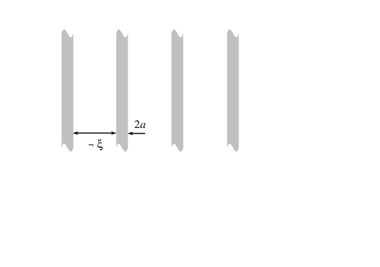
and therefore, in order to avoid cross-talk between two adjacent waveguides the distance between two such waveguides should be increased. This would limit the number of waveguides one can use in a given length (or, more accurately, width).
The bit-rate () for very narrow waveguide is limited by the waveguide dispersion [6]
| (12) |
This is the bit-rate of a single waveguide, which means that the bit-rate per unit of width is
| (13) |
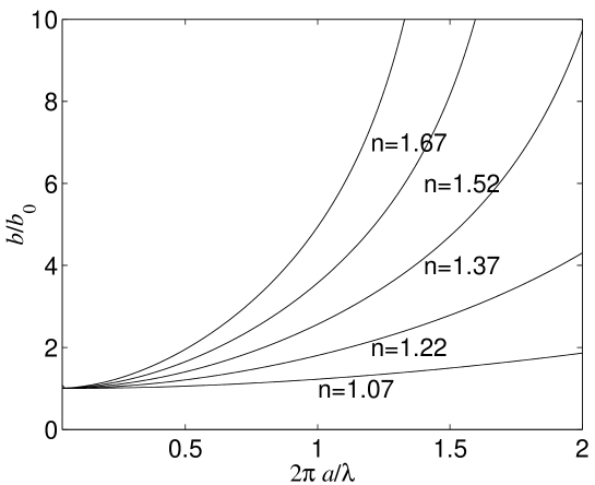
In figure 2 we plot the exact numerical solution of the transmission bit-rate per unit of width (for different refractive indices) as a function of the normalized width . Clearly, when decreases the SC decreases, and for it converges to a universal constant:
| (14) |
This constant is universal in the sense that it is independent of the waveguide’s characteristics (it depends neither on its width not on its refractive index ).
The limiting result (14) is consistent with the limit of information transmission in free space, as we now show.
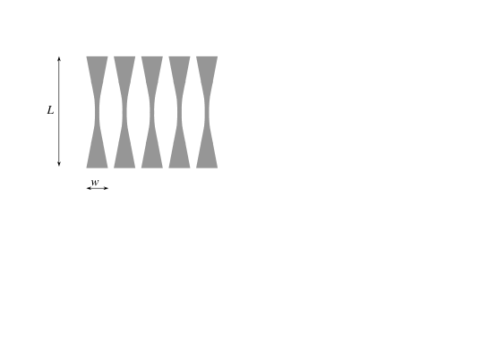
In free space dispersion is not a limitation, however SC will be limited by beam divergence. For Gaussian beams, which possess the smallest divergence, SC will be maximized when transmitting in the confocal configuration. In this case, as shown in Fig.3, the waist is positioned exactly at and is equal to , where is the beam’s width at and at , is the confocal length, and
| (15) |
Since the bit rate cannot exceed the carrier’s frequency (i.e., ) we obtain qualitatively a similar result for SC:
| (16) |
In the 3D case, such as an optical fiber, the SC is lower, since the fibers should be separated in an additional dimension.
The refractive index satisfies
| (17) |
where is now the waveguide’s radius.
The propagation constant similarly satisfies [7]
| (18) |
where is the localization distance in the transversal direction. For simplicity, let us take the most common case where , then [7]
| (19) |
where is the fiber’s V parameter, and is the Euler constant. Clearly, when we obtain
| (20) |
However, since the area around each fiber should be proportional to (to avoid cross-talk in both transversal dimensions) we finally obtain that
| (21) |
Not only does this SC converges to zero, but it is much lower than the SC of the free space result
| (22) |
Note that depends only on the carrier frequency (or wavelength).
To summarize, we have calculated the spatial capacity of slab waveguides (2D case) and fibers (3D case) in the limit of zero width. We have shown that while the bit-rate of a single waveguide (or fiber) is inversely proportional to its width (in the limit), the SC decreases monotonically. In the case of a waveguide it is shown that the SC converges to . This result is independent of the waveguide’s refractive index, and qualitatively similar to the SC of free 2D space.
In the case of fibers (i.e., 3D) however, the SC vanishes in the limit of a zero width waveguide, and is therefore different from the SC of free 3D space.
REFERENCES
- [1] See, for example, a review by D.G. Leeper, Sci. Am., p. 47, May 2002.
- [2] C.E. Shannon, Bell Syst. Tech. J., 27, 379 (1948).
- [3] J.Tang, J. Lightwave Tech. 19, 1104 (2001).
- [4] M.A. Neifeld, Opt. Lett. 23, 1477 (1998).
- [5] E.E. Narimanov and P. Mitra, J. Lightwave Tech. 20, 530 (2002).
- [6] G.P.Agrawal, Fiber-Optic Communication Systems(Wiley-Interscience, New-York 1997).
- [7] A. Yariv, Optical Electronics, 4th edition (Sounders and Harcourt Brace Jovanovich College publishing, Orlando 1991).