Scheme for Attophysics Experiments at a X-ray SASE FEL
Abstract
We propose a concept for production of high power coherent attosecond pulses in X-ray range. An approach is based on generation of 8th harmonic of radiation in a multistage HGHG FEL (high gain high harmonic free electron laser) configuration starting from shot noise. Single-spike phenomena occurs when electron bunch is passed through the sequence of four relatively short undulators. The first stage is a conventional ”long” wavelength (0.8 nm) SASE FEL which operates in the high-gain linear regime. The 0.1 nm wavelength range is reached by successive multiplication (0.8 nm 0.4 nm 0.2 nm 0.1 nm) in a stage sequence. Our study shows that the statistical properties of the high-harmonic radiation from the SASE FEL, operating in linear regime, can be used for selection of radiation pulses with a single spike in time domain. The duration of the spikes is in attosecond range. Selection of single-spike high-harmonic pulses is achieved by using a special trigger in data acquisition system. The potential of X-ray SASE FEL at TESLA at DESY for generating attosecond pulses is demonstrated. Since the design of XFEL laboratory at TESLA is based on the use of long SASE undulators with tunable gap, no special place nor additional FEL undulators are required for attophysics experiments. The use of a 10 GW-level attosecond X-ray pulses at X-ray SASE FEL facility will enable us to track processes inside atoms.
, , and
1 Introduction
A general objective in the development of synchrotron radiation sources is to produce radiation that is brighter than that from existing sources, or to produce radiation that comes in shorter pulses. Significant progress in both of these directions has been reported recently by the TESLA collaboration. The results have been obtained at the TESLA Test Facility (TTF) at DESY [1], using radiation pulses of 100 nm wavelength with sub-100 femtosecond pulse duration and peak power of approximately one GW. Comparing to present day synchrotron radiation sources its spectral brightness is more than a 100 million times higher, the radiation has full transverse coherence and pulse duration is reduced from the 100 picoseconds down to 100 femtoseconds in time domain. These demonstrations have been made possible by the technique of Self Amplified Spontaneous Emission Free Electron Laser (SASE FEL). The generation of radiation in a linac driven SASE FEL has much a common with the generation of radiation in synchrotron source, the main difference in being the power dependence on number of electrons . The radiation generated in synchrotron sources is based on the spontaneous radiation of many electrons uncorrelated in space and time. As a consequence, the radiation power scales linearly with the number of electrons in the bunch. In the SASE FEL technique in order to increase the power and coherence of radiation, one has to force the electrons to emit coherently by compressing them into volume small compared to the wavelength of radiation. With complete micro-bunching, all electrons radiate almost in phase. This leads to a radiation power proportional to and thus amplification of many orders of magnitude with respect to the spontaneous emission. TTF FEL shows that a laser for X-rays can be built on the basis of the SASE FEL principle. Technical design studies were presented for XFEL laboratory [2] which should provide X-rays at wavelengths down to 0.1 nm in pulses of 100 fs duration. Peak spectral brightness would exceed those of synchrotron sources by over ten orders of magnitude. Furthermore soft X-ray SASE FEL project with wavelengths down to 6 nm was started at DESY. Commissioning of this facility will start in the year 2003 [3].
The discussion in the scientific community over the past decade has produced many ideas for novel applications of the X-ray laser. Brilliance, coherence, and timing down to the femtosecond regime are the three properties which have the highest potential for new science to be explored with an XFEL. It is obvious that studies of time dependent phenomena can be tackled for the first time which relate the structural aspects with the transition states of those electrons which are responsible for the formation process of intra-molecular bonds, clusters, nanoparticles, liquids, solids and hot dense plasmas. Femtosecond-resolution experiments with X-rays can possibly show us directly how matter is formed out of atoms. In fact, X-ray pulse duration even shorter than femtosecond may be useful for many scientific applications. A first question that arises is: why do researchers want laser-like X-ray radiation sources with shorter pulse durations? The reason is that phenomena inside atoms occur on sub-femtosecond timescale. Generating single attosecond X-ray pulses is one of the biggest challenges in physics. The use of such a tool will enable us to trace processes inside atoms. If there is any place where we have a chance to test the main principles of quantum mechanics in the pure way, this is it.

Our studies have shown that the X-ray SASE FEL holds a great promise as a source of radiation for generating high power, single attosecond pulses. Two major developments have made this possible. It was shown recently that the statistical properties of the high-harmonic radiation from the SASE FEL, operating in linear regime, can be used for selection of radiation pulses with a single spike in time domain [4]. In the case of X-ray FEL the duration of the spikes is in attosecond range. Selection of single-spike high-harmonic pulses can be achieved by using a special trigger in data acquisition system.


The second development was the invention of single-bunch multistage High Gain Harmonic Generation (HGHG) FEL scheme [5]. In this technique the second harmonic in the th stage becomes the fundamental in the th stage. Each stage (except the first one) consists of radiator undulator, dispersion section (demodulator), FEL amplifier and end-stage dispersion section (modulator). The main difference with previous HGHG schemes [6, 7, 8, 9, 10, 11, 12, 13, 14] is that frequency multiplication is performed with a single electron bunch consecutively passing all HGHG stages. This is possible because the density modulation exiting each stage is relatively small. Hence, a small energy modulation is sufficient to create this microbunching in the dispersion section. In this case the growth of the energy spread due to HGHG process is much less than initial energy spread, and exponential growth rate in the main undulator is practically the same as without stage sequence. At chosen parameters for each stage the amplitude of the second harmonic of density modulation dominates significantly over the amplitude of shot noise harmonics, and the modulation of the beam density can be used as input signal for the next HGHG stage.
The combination of a single-bunch multistage HGHG scheme and a single-spike selection technique is very promising. Our concept of attosecond X-ray facility is based on generation of the 8th harmonic of SASE radiation in the single-bunch, multistage HGHG configuration. Single-spike phenomena occurs when electron bunch is passed through the sequence of four relatively short undulators. The first stage is a conventional ”long” wavelength (0.8 nm) SASE FEL operating in the high-gain linear regime. Figure 1 illustrates how the 0.1 nm wavelength range may be reached by successive multiplication in a stage sequence (0.8 nm 0.4 nm 0.2 nm 0.1 nm).
The final steps involved in obtaining a single-spike pulses of the 8th-harmonic radiation are as follows. The energy in the high-harmonic radiation pulse must be measured by means of a non-destructive method. After each shot, the signal from the energy detector is sent to a discriminator having a threshold , where is the mean energy of the 8th harmonic (averaged over the ensemble of pulses) After discrimination signal is used to give a trigger. A register is used to store information concerning the trigger and sample detector events. A schematic, illustrating these processes, is shown in Fig. 2.
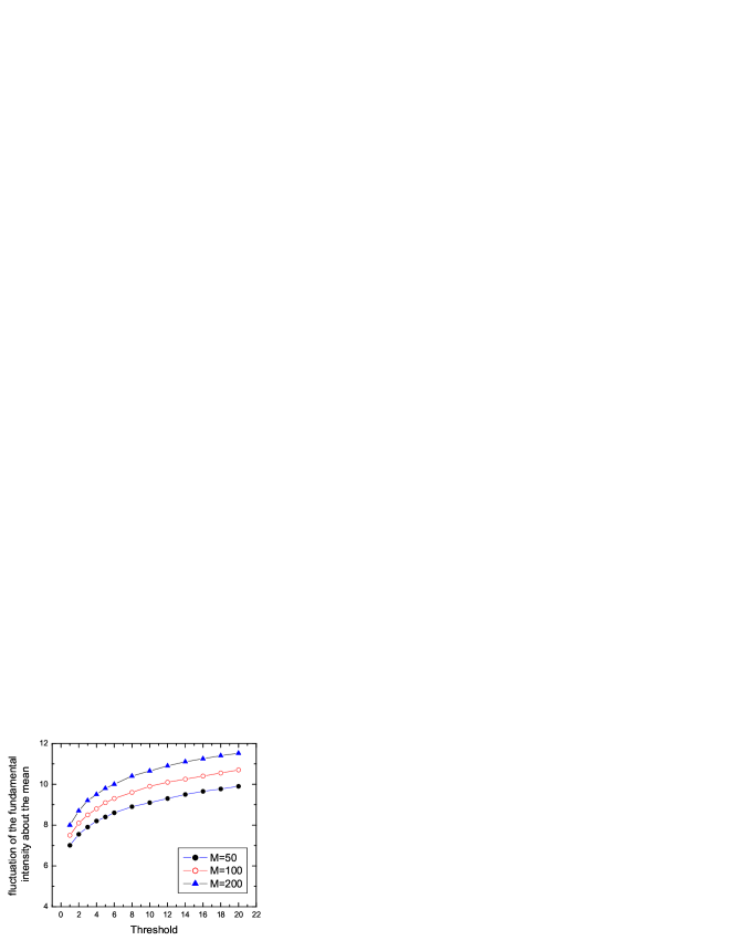
The possibility of single-spike pulse selection is demonstrated in a simple example. With reference to Fig. 3 consider an intensity function in the SASE FEL radiation pulse at fundamental frequency versus time . Subjecting it, for example, to a 8th harmonic transformation, we obtain the ”image” shown in Fig. 4. An important distinction should be made between the sample fundamental instantaneous intensity function (see Fig. 3) and the transformed function (see Fig. 4). Due to the nonlinear generation mechanism, the temporal structure of the 8th-harmonic radiation is similar to the fundamental, but with more fluctuations from spike to spike. The fact that the 8th harmonic intensity is a single spike implies that the fluctuation of the fundamental intensity about the mean is rather pronounced. How likely are we to observe a practically single bright spike in the intensity of the 8th harmonic radiation? Clearly, a necessary condition for this event is that the energy in the 8th-harmonic radiation pulse is larger than the average energy . The results of numerical simulations for the case of the 8th-harmonic of the X-ray SASE FEL predict the probability of high-contrast single-spike pulses of about 1–10% only. For this method to be applicable, the electron pulse repetition rate should be larger than 100 pulses per second.
This paper describes the scheme for attophysics experiments that could be performed at the X-ray SASE FEL at TESLA. The superconducting linear accelerator is an ideal accelerator to drive an attosecond XFEL. The high repetition rate of the TESLA accelerator (52000 pulses per second) should be sufficient to obtain average kHz-level pulse repetition rate of single spikes. The development and test of attosecond X-ray FEL at TESLA is greatly facilitated by the fact that undulators with required parameters are being developed in the framework of SASE option of X-ray FEL at TESLA. Also, the length foreseen for installation of SASE undulators is sufficient to accommodate attosecond option.
2 Statistical properties of SASE FEL high-harmonic radiation
The principle of operation of the proposed scheme is essentially based on the statistical properties of the SASE FEL harmonic radiation. SASE radiation is a stochastic object and at a given time it is impossible to predict the amount of energy which flows to a detector. The initial modulation of the electron beam is defined by the shot noise and has a white spectrum. The high-gain FEL amplifier cuts and amplifies only a narrow frequency band of the initial spectrum . In the time domain, the temporal structure of the fundamental harmonic radiation is chaotic with many random spikes, with a typical duration given by the inverse width of the spectrum envelope. Even without performing numerical simulations, we can describe some general properties of the fundamental harmonic of the radiation from the SASE FEL operating in the linear regime. Indeed, in this case we deal with Gaussian statistics. As a result, the probability distribution of the instantaneous radiation intensity should be the negative exponential probability density distribution: . Here one should realize clearly that the notion of instantaneous intensity refers to a certain moment in time, and that the analysis must be performed over an ensemble of pulses. Also, the energy in the radiation pulse should fluctuate in accordance with the gamma distribution [16]:
where is the gamma function of argument , and is the normalized dispersion of the energy distribution. These properties are well known in statistical optics as properties of completely chaotic polarized radiation [17].
Let us turn to discussion of statistical properties of the high-harmonic radiation in a SASE FEL. It should be noted that the statistics of the high-harmonic radiation from the SASE FEL changes significantly with respect to the fundamental harmonic (e.g., with respect to Gaussian statistics). It is interesting in our case to be able to determine the probability density function of instantaneous intensity of SASE radiation after it has been subjected to nonlinear transformation. We know the probability density function of the fundamental intensity , and is subjected to a transformation . The problem is then to find the probability density function . It can be readily shown that . Using this distribution we get the expression for the mean value: . Thus, the th-harmonic radiation for the SASE FEL has an intensity level roughly times larger than the corresponding steady-state case, but with more shot-to-shot fluctuations compared to the fundamental [18]. Nontrivial behavior of the intensity of the high harmonic reflects the complicated nonlinear transformation of the fundamental harmonic statistics. One can see that Gaussian statistics is no longer valid.
Since amplification process starts from shot noise, properties of a single-spike selection should be dscribed in statistical terms. The statistics of concern are defined over an ensemble of radiation pulses. If we define the contrast as the ratio of number of photons in the main spike to the total number of photons in the pulse, we find that asymptotically approaches unity as the ratio increases, where is the threshold level of the 8th harmonic energy pulse discriminator. Clearly, the larger the threshold level of discriminator , the larger the number of shots per trigger pulse . Note that the number of degrees of freedom of the fundamental radiation pulse is a parameter of the functions as indeed we might have anticipated.

Our goal is to find the relationship between the level of the discriminator , contrast factor , and number of shots per trigger pulse . In addition, we wish to find effects of the number of modes on the single spike selection. To find an approximate, density function of integrated intensity we invoke a quasi-physical arguments as follows [17]. As an approximation for fundamental harmonic, the smoothly fluctuating instantaneous intensity curve may be replaced on the interval by a ”boxcar” function (see Fig. 5). The time interval is divided into equal length subintervals. Within each subinterval, the approximation to is constant; at the end of each subinterval, the approximate waveform jumps to a new constant value, assumed statistically independent of all preceding and following values. The probability density function of the boxcar function within any one subinterval is taken to be the same as the probability density function of the instantaneous intensity at a single time instant .
The integrated fundamental harmonic intensity is now approximated in terms of the area under the boxcar function:
where is the width of one subinterval of the boxcar function and is the value of the boxcar function in the th subinterval. By hypothesis, the probability density function of each is taken to be the same as the density function of the instantaneous intensity. Also by hypothesis, the various are assumed to be statistically independent.
This particular density function of the fundamental radiation energy per pulse (integrated intensity) is known as a gamma probability density function, and accordingly the random variable is said to be (approximately) a gamma variate. Continuing with the case of fundamental harmonic, one problem remains: the parameters of the density function must be chosen in such a way as to best match the approximate result to the true density function of . The only two adjustable parameters available are and variance . The most common approach taken is to choose the parameters such that mean and variance of the approximate density function are exactly equal to the true mean and variance of fundamental radiation energy [17].
It should be noted that, in a certain sense, our quasi-physical reasoning that led to the approximate distribution has broken down, for in general the parameter is not an integer, where as we implicitly assumed an integer number of subintervals in the boxcar function. In what follows we use the following assumption: . Such assumption does not reduce the practical applicability of the result obtained. It is obvious that this single-spike scheme has an advantage over usual SASE scheme only when the SASE radiation pulse is much longer than the single spike.
Our approximate model assumes that the smoothly fluctuating SASE intensity curve can be replaced by a ”boxcar” function. Such a model allows us to express the radiation pulse after application of frequency multiplication as the sum of the therms, too. The integrated intensity of 8-th harmonic is now approximated in therms of the area under the boxcar functionals as follows:
Note, that is the average number of degrees of freedom (or modes) in the fundamental radiation pulse.
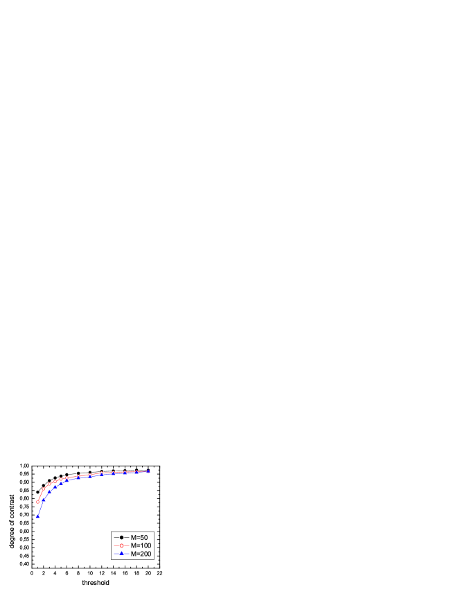
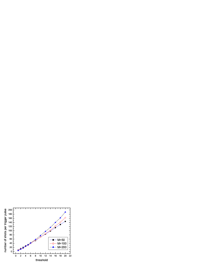
In Figs. 6 and 7 one can see the basic characteristics of the single-spike pulse selection process. The dependence of the degree of the contrast on the value of the energy threshold is presented in Fig. 6. It is seen that the contrast increases with an increase in the value of energy threshold, and it asymptotically approaches to unity. Simulations at different values of show that the degree of contrast does not differ significantly when the number of modes is within the limits . Figure 7 shows plots of the number of shots per trigger pulse versus for several values of the parameter . From Fig. 7 it is quite clear that the dependence of on the number of modes is not strong within the interval and can be ignored.
With the preceding results in hand, it should now be possible to estimate, for example, the repetition rate of the single-spike pulse. In the case of TESLA X-ray FEL, the number of modes in the fundamental radiation pulse at a wavelength of 0.8 nm is about . Suppose that we wish to achieve a contrast of 90%. The discriminator threshold required to achieve this contrast is about . If the number of modes is close to , plot in Fig. 7 shows that the number of shots per trigger pulse is about 10. Hence, the single-spike pulse repetition rate is still high (about a few thousands single-spike pulses per second). On the other hand, if the contrast of interest is 97% , the number of shots is about , and repetition rate of the single-spike pulse decreases up to a few hundreds per second.
A few additional comments are needed in closing this section. The results of numerical simulations presented above refer to the specific model which depends on one parameter only. This model has proven to be very fruitful, providing the possibility of performing fast numerical simulations of the main statistical characteristics of the high-harmonic radiation from the SASE FEL operating in the linear regime. There is no doubt that these results are useful for quick estimate and deeper understanding of the frequency multiplication process in a SASE FEL. The disadvantage of this approach is in neglecting the radiation spectral profile and electron bunch profile effects. As a result, the method described above is rather crude and may be modified in use. The full analysis of single-spike generation, including both of these effects, is a very expensive for computer run. Fortunately, in the particular case, namely of radiation originated from an electron bunch with rectangular profile, a much simplified analysis will suffice. An approach, which takes into account the spectral line shape effects, uses a well known analytical expression for steady-state spectral Green function of the FEL amplifier [16]. We can decompose the input shot noise signal into Fourier harmonics. Since in the linear regime all the harmonics are amplified independently, we can use the results of steady-state theory for each harmonic and calculate the corresponding Fourier harmonics of the output radiation field. An expression for the electric field of the electromagnetic wave as a function of time can be obtained using the inverse Fourier transform. In the framework of this model it becomes possible to calculate the smooth sample functions and .
To describe the single-spike selection, we should define the degree of contrast. A first question that arises is: what is the definition of the main spike? The question of when two closely spaced spikes are barely resolved is a complex one and lends itself to a variety of rather subjective answers. One possible definition can be made as follows. After analysis of smooth sample function we find a time moment when the intensity reaches its maximum value. Then we find the number of photons within the time interval , where is coherence time of the 8th harmonic radiation pulse. In fact, the ability to resolve two spikes depends fundamentally on the discriminator level associated with the selected 8th harmonic pulse, and for this reason for large ratio, , this problem does not exist at all. It can be demonstrated that all reasonable definitions for the degree of contrast are consistent in the region .
While adding realism, the step from ”boxcar” function to smooth sample function drastically increases computer time. Nevertheless, one can learn much about accuracy of the ”boxcar” scheme by seeing how it reproduce ”exact” results of numerical simulations for several values of the discriminator threshold. Surprisingly, we can find that the results of the more general approach does not differ significantly with those of the far simpler analysis done previously.
3 Attosecond X-ray facility description

In this section we are going to discuss the application of the idea of the single-spike generation to a practical case, the XFEL at TESLA [2]. An attosecond laser requires a broadband gain medium. What ultimately limits the pulse duration? Since the temporal and spectral characteristics of the field are related to each other through Fourier transforms, the bandwidth of XFEL and pulse duration cannot vary independently of each other. There is a minimum duration-bandwidth product: . The larger the FEL bandwidth is, the shorter the minimal pulse duration than can be obtained. This simple physical consideration can lead directly to crude approximation for the minimum duration of the XFEL radiation pulses. We can expect that the width of the radiation spectrum at 0.1 nm wavelength should be of order of [2]. Thus, the minimum duration should be as. To illustrate the later point, let us consider the details of X-ray SASE FEL radiation. The physical reason for this is as follows. A SASE radiation is a situation in which the radiation pulse consists of a large number of independent wavepackets (spikes) with a typical duration given by the inverse width of the spectrum envelope. Typical temporal structures of the radiation pulse from the X-ray SASE FEL is presented in Fig. 8. The chaotic nature of the output radiation is a consequence of the start-up from shot noise. This plot also indicates that the shortest XFEL pulse duration is approximately attoseconds.
The layout of the attosecond facility at TESLA is shown schematically in Fig. 9. Single-bunch HGHG scheme consists of three stages of frequency doubling and main undulator. It has been pointed out that for single-spike selection scheme to work, the chain of FEL amplifiers must operate in linear regime. An intrinsic advantage of the adopted HGHG scheme is the linear mode operation. The first stage of frequency doubling (0.8 nm 0.4 nm) consists of SASE FEL undulator and dispersion section for the beam density modulation. The scheme operates as follows. The first stage is a conventional FEL amplifier seeded by shot noise. Radiation power is exponentially amplified upon passing through the first undulator. The amplitude of energy modulation of the electron beam at the undulator exit is equal to , where is the initial local energy spread in the electron bunch. Calculations show that in this case the beam density modulation is not sufficient to drive the second stage. Required value of the beam bunching at the second harmonic of about 5% is achieved when the electron bunch passes through the dispersion section (the density modulation at the fundamental frequency is about 0.3). In this situation the amplitude of the second harmonic of the density modulation dominates significantly over the amplitude of shot noise harmonic (of about 0.03%), and it serves as input signal for the second stage.

Let us discuss the problem of optimization of the first SASE FEL. The function of the first SASE FEL is to prepare electron bunch with energy modulation at the 0.8 nm wavelength. The process of amplification of radiation in this undulator develops in the same way as in conventional SASE FEL: fluctuations of the electron beam current density serve as the input signal. To estimate the value of the input signal at fundamental harmonic related to single spike at the 8th harmonic, it is convenient to introduce the notion of an effective power of shot noise , which is usually used for numerical simulation of the SASE FEL (see, e.g., [16]). For the 0.8 nm SASE FEL the effective shot noise power is about kW. Calculation shows (see Fig. 10) that the fluctuation of the instantaneous power at fundamental harmonic related to single spike at the 8th harmonic is about 10 times larger than the mean value. This means that effective peak power of the ”seed” spike is about 10 kW. At the exit of the first undulator the most fraction of the electron beam has small energy modulation due to the FEL process except of the small (”seed” spike) region. Since the instantaneous radiation power in this region is about 10 times larger, only this small part of the electron bunch produces in dispersion section the input signal at the 0.4 nm for the 2nd HGHG stage, thus providing short pulse duration. Upon passing through the first FEL undulator, radiation is exponentially amplified. First FEL operates in a linear regime with a power gain . This value is much less than the power gain at saturation, . At such a choice of the power gain in the first undulator the energy modulation (in small ”seed” spike region) induced by the FEL process amounts to 1.5 MeV and is about two times less than the initial energy spread (about 2.5 MeV) in the beam. The amplitude of the first harmonic of the beam density modulation related to this energy modulation is about 2% only. Since this density modulation is of about 10 times smaller than required value, one should use dispersion section at the exit of the first stage.

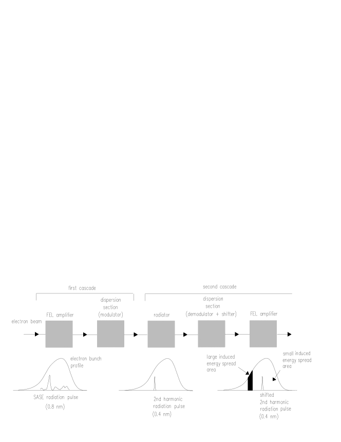
The design configuration of the second stage is shown in Fig. 11. The stage consists of a short undulator (radiator), dispersion section (demodulator), high-gain FEL amplifier and end-stage dispersion section (modulator). Following the first stage the beam and seed radiation enter short undulator (radiator) which is resonant with the second harmonic of the seed radiation (0.4 nm). In the radiator the seed radiation at fundamental harmonic plays no role and is diffracted out of the electron beam. However, a new 0.4 nm radiation is generated by the density-modulated electron beam and rapidly reaches 10 MW-level peak power. After the radiator the electron beam is guided through a dispersion section (magnetic chicane). The trajectory of the electron beam in the chicane has the shape of an isosceles triangle with the base equal to . The angle adjacent to the base, , is considered to be small. The problem of suppressing the beam modulation induced in the first stage can be solved quite naturally due to the presence of the local energy spread in the electron beam. Parameters in our case are: mrad, m, compaction factor m, 0.8 nm, = 0.8 nm. This leads to the suppression of the electron beam modulation by a factor (for Gaussian energy distribution). The demodulators needed for HGHG stages has to satisfy two additional requirements. First, the radiation pulse must overlap the electron bunch at the chicane exit, i.e. the electron beam extra path length must be much smaller comparing with the electron bunch length. Second, coherent synchrotron radiation (CSR) effects should be avoided in order tp preserve transverse emittance. In the present design of HGHG scheme we have only about 4 m extra path length for the electron beam, while the rms length of electron bunch is about 25 m, thus delay effect is negligible. Calculation of the CSR effects shows that this should not be a serious limitation in our case.
Passing the chicane the demodulated electron beam and seed 0.4 nm radiation enter the FEL amplifier undulator. This undulator is long enough to reach 0.6 energy modulation at the wavelength of 0.4 nm. Since the density modulation at 0.4 nm is of about 10 times smaller than required value, one should use dispersion section at the exit of the second stage. After passing second dispersion section, the energy modulation induced in the beam by amplification in the FEL amplifier transforms into the density modulation. The values of the second (0.4 nm) and the 4th (0.2 nm) harmonics of density modulation at the second stage exit are about 30% and 5%, respectively. These values are approximately the same as the amplitudes of the first and second harmonics at first stage exit.
Following the second stage the beam enters the third stage which is resonant with the 4th harmonic (0.2 nm). Like the second stage, the third stage also consists of the radiator, demodulator, FEL amplifier and modulator. Now 0.2 nm density modulation serves as a seed for this radiator. The dispersion section needed for third stage has only about 2 m extra path length for the electron beam. In this case no problem of synchronization between radiation pulse and electron bunch occurs. The length of the FEL amplifier undulator is chosen in such a way that the energy modulation at the undulator exit has the value of . Required value of the beam bunching at the 8th harmonic (0.1 nm) of about 10% is achieved when the electron beam passes through dispersion section.
Finally, after the third stage the electron beam enters the main undulator system which is resonant to the 8th harmonic (0.1 nm). This undulator system consists of the radiator undulator, dispersion section and FEL amplifier which operates in a linear regime with a power gain of about . This value is much less than the power gain of 0.1 nm SASE FEL at saturation, . The attosecond XFEL will provide transversely coherent bandwidth limited single-spike pulses. Frequency multiplication can be an essential pulse shortening mechanism in a multistage HGHG scheme. Because of the nonlinearity of the conversion process, one expects the generation of double frequency pulse times shorter than the pulse duration at the fundamental frequency (for Gaussian profile). Successive multiplication to the th harmonic resulting in -fold compression of the th harmonic pulse duration. In our case , and numerical simulations show that we can obtain 600 attosecond pulses at the wavelength of 0.1 nm. The number of photons can exceed per pulse.
The small energy perturbation of the electron beam is one of the advantages of the adopted HGHG FEL design. In our scheme the energy modulation (i.e. correlated) energy spread induced in the th stage, transforms to local (i.e. uncorrelated) energy spread in the th stage. As a result, the dispersion of the electron energy distribution at the exit of the multistage scheme is calculated as the sum of induced dispersions. For instance, the total energy spread generated to the end of the first demodulator, can be estimated as
for . Such a small degradation of the energy spread almost does not lead to degradation of output radiation.
One can wonder why presenting calculation of the energy spread induced in the first stage we use the value . It should be reemphasized that the function of the first SASE FEL is to prepare electron bunch with energy modulation at the 0.8 nm wavelength. Here we direct the attention of the reader to the fact that this level of the energy modulation takes place only at that part of the electron bunch, defined by the length of the ”seed” spike. Fluctuation of the instantaneous power at fundamental harmonic related to single spike at the 8th harmonic is about 10 times larger than mean value (see Fig. 10). This means that at the exit of the first undulator the most fraction of the electron beam has 3 times smaller energy modulation due to the FEL process except of the small (”seed” spike) region. The resulting radiation produced in the radiator of the second stage is shifted to the part of electron bunch with small induced energy spread. This shift is done by passing the electron beam through the first magnetic chicane (demodulator) so as to delay the electrons by a time equal to 12 fs. On the other hand, the single-spike pulse duration at 0.8 nm wavelength is about 2 fs only. A schematic diagram of the second harmonic generation is shown in Fig. 12 as well as the relative positions of the radiation and electrons before and after the bunch shift. This is to some degree surprising: best results were obtained in hybrid operation, using chicane as demodulator, and as magnetic delay. So, this is the important concept: we use a magnetic delay to position the 0.4 nm radiation at the ”fresh” part of the electron bunch. The radiation starts interacting with a new set of electrons, which have the small energy spread, since they did not participate in the previous interaction with ”seed” spike. Actually, this is the essence of the ”fresh bunch” techniques which was introduced in [15]. The ability to shift the radiation to ”undisturbed” part of the electron bunch after each harmonic generation is important advantage of the proposed scheme. This advantage (hybrid operation) explains why we expect a total energy spread growth at the main (0.1 nm) undulator of about a few per cent only.
| SASE4 | SASE5 | |
| Type | planar | circular |
| external beta-function, m | 45 | 45 |
| magnetic period, mm | 60 | 107 |
| electron energy, GeV | 25 | 25 |
| magnetic gap, mm | 22-12 | 35-12 |
| magnetic field, T | 0.66-1.33 | 0.38-0.96 |
| photon wavelength, nm | 0.1-0.35 | 0.4-2.5 |
| parameter | 4-6 | 15-30 |
| total length, m | 323 | 177 |
Let us to discuss some general aspects of noise influence on the attosecond facility operation. In [5] we performed a detailed study of process of amplification in the HGHG FEL schemes taking into account shot noise in the electron beam. It has been found that a general disadvantage of HGHG FEL schemes (as well as any frequency multiplication scheme) is strong noise degradation of the properties of output radiation with increasing harmonic number . In the case of HGHG FEL this means that the effect of frequency multiplication by a factor of results in multiplication of the ratio of noise power to carrier by a factor of . An attractive feature of proposed HGHG scheme is that multiplication factor is equal to only. Here it is relevant to remember that amplification process in attosecond facility starts from shot noise and problem of noise in the first HGHG cascade does not exist at all. Considering the other contributions to the noise output, it is obvious that the condition will not be violated if when taking into account of the second and third stage contributions to the noise output. It is important to note that noise degradation discussed above takes place at that part of the electron bunch, defined by the length of the ”seed” single spike. Nevertheless, the problem of noise degradation is more complicated and there is another noise effect that can be important for ultra-short X-ray pulse generation. We must account to that shot noise in the main part of electron bunch can provide long pulse SASE radiation in the main undulator. This effect leads to degradation of contrast of output attosecond X-ray pulses. However, parameters of the third stage and main undulator can be optimized in such a way that this degradation of contrast is insignificant.
Now we would like to discuss in more detail a single-spike contrast preservation during amplification process in the main undulator. The long main undulator can emit a SASE radiation pulse with duration of about 200 times longer than the seed ultra-short pulse. In view of this, the preservation of degree of single-spike pulse contrast is clearly of critical importance to the operation and scientific utility of the attosecond X-ray facility. The criteria that led to the selection of the third cascade and main undulator parameters were established by first determining the minimum value of main undulator gain. The smaller the main undulator gain, the better the contrast of attosecond pulses and additionally the smaller the cost of undulator systems. For this reason, the best way to reduce the gain of main undulator is by generating maximum 8th harmonic in the spatial bunching at the third cascade exit. The optimum spatial bunching, keeping the linear mode operation, results in an amplitude of 8th harmonic of 10%. Optimized gain of the main undulator is equal to . Calculation shows that in this case the ratio of the SASE pulse energy and attosecond pulse energy at the main undulator exit reaches a value of about per cent only. Thus, we find that effects of SASE radiation in the main undulator are not important in our case.
For the TESLA XFEL project five SASE FELs are planned in total [2]. Two undulators (SASE2, SASE3) have a fixed gap. On SASE1, SASE4, SASE5 undulators the magnet gap will be varied mechanically for wavelength tuning. The total length of undulator systems is 1700 m. This huge length, with as much as 281 segments, calls for standardization and an economic design, that is optimized for the production of large quantities. The total length of an undulator system is much longer than the optimum -function. External strong focusing is therefore needed to keep the -function within limits acceptable for the FEL process. The undulator system may be separated into undulator segments and strong focusing quadrupoles. The undulator system for an X-ray FEL is a long periodic array of undulator segments and intersections. Each cell consists of one undulator segment and the components in the intersections such as a phase shifter, correctors, a quadrupole, and beam position monitors. Table 1 summarizes the proposed design parameters for gap-tunable SASE4 and SASE5 undulators. We mention it here only for illustration. The HGHG scheme also requires the use of gap tuning. The great advantage of proposed design is that attosecond X-ray facility undulators are shortened versions of the SASE4 and SASE5 undulators. The proposal for the undulator systems for HGHG scheme is based exclusively on the standardized components. Only two different types of magnet structures are needed. The total magnetic length of SASE5-type structure for first and second HGHG stages is 80 m, and length of SASE4-type structure for the third stage and main undulator is 160 m. This length is taken as the net magnetic length of the undulator. The total length of undulator systems includes 20% contingency for field errors, misalignment, etc.
Acknowledgments
We thank W. Brefeld, B. Faatz, J. Feldhaus, M. Körfer, J. Krzywinski, T. Möller, J. Pflüger, J. Rossbach, and S. Schreiber for many useful discussions. We thank J.R. Schneider and D. Trines for their interest in this work and support.
References
- [1] V. Ayvazyan et al., DESY-print 01-226(2001), Phys. Rev. Lett. 88(2002)104802
- [2] F. Richard et al. (eds), TESLA Technical Design Report, DESY2001-011, and http://tesla.desy.de
- [3] M. Koerfer, ”The TTF-FEL status and its future as soft X-ray user facility” presented at 23rd Int. FEL Conf. (Darmstadt, Germany 2001), Nucl. Instrum. and Methods A in press.
- [4] W. Brefeld, et al., Preprint DESY 02-038, DESY Hamburg, 2002
- [5] E. L. Saldin, E. A. Schneidmiller and M. V. Yurkov, Opt. Commun. 202(2002)169
- [6] I. Boscolo, V. Stagno, Nuovo Cimento B 58(1980)267
- [7] I. Schnitzer, A. Gover, Nucl. Instr. Meth. A 237(1985)124
- [8] R. Bonifacio, L. De Salvo, P. Pierini, Nucl. Instr. Meth. A 293(1990)627
- [9] L. H. Yu, Phys. Rev. A 44(1991)5178
- [10] I. Ben-Zvi et al., Nucl. Instr. Meth. A 304(1991)151
- [11] I. Ben-Zvi et al., Nucl. Instr. Meth. A 393(1997)II-10
- [12] L. H. Yu, I. Ben-Zvi et al., Nucl. Instr. Meth. A 393(1997)96
- [13] L. H. Yu et al., Nucl. Instr. Meth. A 445(2000)301
- [14] J. Wu, L. H. Yu Nucl. Instr. Meth. A 475(2001)104
- [15] I. Ben-Zvi, K. M. Yang, L. H. Yu, Nucl. Instr. Meth. A 318(1992)726
- [16] E. L. Saldin, E. A. Schneidmiller and M. V. Yurkov, ”The Physics of Free Electron Lasers” (Springer-Verlag, Berlin-Heidelberg-New York, 1999)
- [17] J. Goodman, ”Statistical Optics” (Willey, New York, 1985)
- [18] Z. Huang and K.-J. Kim, Phys. Rev. E 62, 7295(2000)