AN UNEXPECTED EFFECT IN ALEPH: LONG-TERM DISPLACEMENT OF THE SILICON VERTEX DETECTOR
The ALEPH Silicon Vertex Detector for LEP2 featured a laser survey system to monitor its mechanical stability. The analysis of laser system data from 1997 to 2000 showed that VDET suffered a time-dependent displacement. It resulted to be compatible with a deformation of the support structure that made the device to slowly rotate during the data-taking. A maximal local displacement of 20 was observed, corresponding to a rotation of . The implementation of a time-dependent correction on the alignment by using the laser system data led to sizeable improvements on the ALEPH data quality.
1 The ALEPH Silicon Vertex Detector
Many physics studies of the high energy phase of LEP (LEP2) relied on powerful heavy-flavour tags provided by high-resolution vertex detectors.
The ALEPH Silicon Vertex Detector (VDET) had an active length of 40 and consisted of two concentric cylindrical layers of 144 micro-strip silicon detectors of 5.36.5 with double-sided readout. The cylinders’ axes coincided with the nominal beam axes, i.e. the -axis in the ALEPH reference system. Six silicon detectors were glued together and instrumented with readout electronics to form the VDET elementary unit (face). The inner layer (6.3 radius) was formed by 9 faces, the outer layer (10.5 radius) consisted of 15 faces.
2 Laser System
VDET featured a laser survey system to monitor its mechanical stability with respect to the external tracking devices, since an undetected large movement ( 20) of VDET during the data-taking could have degraded significantly its performances. The VDET alignment was normally performed at the beginning of the annual data-taking with events collected during a dedicated calibration run at the Z resonance peak. Afterwards the reduced event rate of LEP2 energies did not allow a precise survey to be done by using particle tracks, and the laser system thus played a crucial role in monitoring the stability of the device.
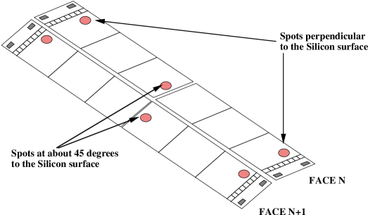
The system made use of infrared light () from two pulsed laser diodes with an output power of W each and a pulse length of . The light was distributed via optical fibers to prisms and lenses attached to the inner wall of the Inner Tracking Chamber (ITC, the closest outer detector). The lenses focused several light beams on 14 of the 15 VDET outer faces. Information on the VDET displacements with respect to the ITC were obtained by monitoring the laser beam impact position (spot) on the silicon wafers. All laser beams were nominally parallel to the ()-plane. As shown in Fig. 1a and in Fig. 1b, there were normally three spots per face: the ones close to the face ends had the beam direction normal to the silicon surface; the one placed about in the middle had the beam direction at 45∘ with respect to the silicon surface, in order to be also sensitive to displacements normal to the face.

The system was operating during standard data-taking: the lasers were fired approximately every 100 physics triggers (i.e. once per one to two minutes) and the spots were reconstructed as standard particle hits. The spot position resolution was impressive, typically 0.5–, thanks to the large signal and the cluster width extending over more than one readout strip. After the installation five spots out of 44 were missed, probably due to misalignment or breakage of the optics. The number of collected laser events was 62k in 1997, 129k in 1998, 125k in 1999, and 170k in 2000.
3 Analysis of Laser System Data
The analysis of the laser system data consisted in studying the time dependence of the spot positions. Along with the expected short-term displacements due to temperature effects , a long-term dependence was discovered in ()-spot positions since 1997. As an example, this behaviour over the entire data-taking period in 2000 is shown in Fig. 2a and in Fig. 2b, referring to endcap A () and endcap B () spots, respectively. Some time-chart is not present because the corresponding spot was missing or removed from the analysis because of low quality . The size of the ()-displacements was systematically dependent on the face azimuthal position, in some case being as large as 10–20, thus comparable to the charged track single hit resolution (10). On the contrary, the -side deviations did not show any critical effect.


The long-term deviations were likely to be due to a global rotation of VDET in the ()-plane, as suggested by the distinctive geometrical configuration. The deviations were thus parametrized under the assumption that VDET was moving as a rigid body, i.e. by using three parameters to correct the nominal alignment: the -translation, the -translation and the rotation angle around the -axis. These were extracted by a fit procedure. As an example, Fig. 2c reports the parameters relative to year 2000 plotted as a function of the time from the beginning of the data-taking. A pictorial view of the corresponding VDET displacement is shown in Fig. 3a and in Fig. 3b. The reconstructed motion was consistent with a rotation and the rigid body model was found to reproduce the observed spot deviations within a few microns . The maximum -rotation value was 7rad in 1997, 8rad in 1998, 3rad in 1999 and 9rad in 2000.
During the last three years of LEP running, several runs at the Z resonance peak were also taken for calibration purpose, during and at the end of the data-taking. The standard alignment performed by using these calibration data allowed to independently confirm the motion of VDET as extracted from the laser system, definitely proving its reliability. A time-dependent correction of the alignment based on the laser data was thus applied from 1998 on.
The correction had a sensible impact on the data quality. This was pointed out studying the Z calibration runs, where a significant amount of data was collected in a period of time much shorter than the time-scale of the effect under observation. Figure 3c and Fig. 3d shows the distribution of the sum of the impact parameters of the two muons in events, before and after applying the laser correction. The plots refer to the Z calibration run taken in 2000, 150 days after the beginning of data-taking, when the displacement averaged over all VDET faces was about 10. Without the correction the systematic shift of the distribution is of the same order of magnitude. Applying the laser correction the mean of the distribution is again compatible with zero.
The rotation may be explained considering that VDET is supported by flanges which slot into two long metal rails located at the top and bottom of the ITC inner cylinder. The top flanges were not metallic as the bottom ones, but made of springy plastic to compensate for distance variations between the rails along which VDET slided during the installation. The VDET environmental conditions during running were quite different with respect to the shutdown period, both in terms of temperature and humidity. They probably had some long-term effect on the material of the plastic flanges, causing a tiny deformation that made VDET to slowly rotate around the lower rail (represented by the small crosses in Fig. 3a and in Fig. 3b).
As a further indication of the environmental conditions as the possible cause, the deformation was found to recover during the shutdown. In the 1999–2000 shutdown VDET was not removed for maintenance allowing its position to be monitored. At the beginning of the data-taking in 2000 the position resulted again the same as at the beginning of the data-taking in 1999.
Extrapolating the LEP experience to the next generation of experiments, the design issues of the Silicon Tracker devices for LHC turn out to be extremely challenging. The huge scale involved forces the effects as the one here described to be carefully taken into account. In fact, as an example, studies for the CMS Tracker support structure have shown that a variation of environmental humidity may lead to material deformation with very long time-scale .
4 Conclusions
The laser system of the ALEPH Vertex Detector for LEP2 was a simple but extremely effective survey system. It allowed a reliable and high-precision monitoring of the VDET position during the data-taking revealing a tiny long-term rotation. An alignment correction based on the information from this system was successfully applied.
References
- [1] D. Creanza et al., The new ALEPH Silicon Vertex Detector, Nucl. Instrum. Methods A 409 (1998) 157; ALEPH Collaboration, The ALEPH Handbook 1995, ed. C. Bowdery, ISBN 92-9083-073-5 (1995).
- [2] A. Wagner, H. Dietl, The Laser Calibration System for VDETII, ALEPH 97-006 (1997).
- [3] G. Sguazzoni et al., Monitoring the Stability of the ALEPH Silicon Vertex Detector, Nucl. Phys. B 78 (1999) 301.
- [4] S. Da Mota Silva et al., Hygro-Thermal Transient Analysis for Highly Stable Structures, CMS CR 1999/014 (1999), published in “Proceedings of ICCM-12, 12th International Conference on Composite Materials, 1999, Paris”.